Note: Descriptions are shown in the official language in which they were submitted.
CA 02796486 2012-11-22
CONTROLLED IMPACT RESCUE TOOL IMPACT ELEMENT
BACKGROUND
[00011 The subject matter disclosed herein relates to an impact element and,
more
particularly, to an impact element of a controlled impact rescue tool (CIRT).
[00021 Urban search and rescue teams often need to create openings (called
"breaches") in rigid structures, such as reinforced concrete walls, to reach
victims in buildings
after a disaster, such as an earthquake or a hurricane. To facilitate the
search and rescue
effort, breaching equipment should be portable, easy to operate and rapid in
effect while not
destabilizing the building structure or threatening injury to operators or
victims.
[0003] Techniques for breaching concrete walls often include gasoline and
hydraulic
powered diamond chain saws, gasoline and hydraulic powered circular saws,
diamond wire
saws, large bore corers, hydraulic/pneumatic/electric impact tools, water jets
and hydraulic
splitters. These techniques all typically require several hours to breach a
thick, heavily
reinforced concrete wall and the equipment may not be portable in some
instances. Military
teams also use explosives to quickly breach walls, but this is dangerous to
victims and can
destabilize the structure. Lasers have also been proposed for breaching
applications, but size,
safety and power constraints generally make them infeasible.
[0004] Accordingly, devices and methods are needed that address one or more of
the
aforementioned shortcomings of conventional reinforced concrete breaching
devices and
methods. US Patent No. 7,814,822 thus proposed to provide an impact element
and a self-
contained energy source. The self-contained energy source enables the impact
element to
impact a first surface of a structure. The impact element is configured to
transmit a localized
shock wave through the structure upon impact. The self-contained energy source
is capable of
accelerating the impact element to a velocity sufficient to induce spalling at
a second surface
of the structure.
1
CA 02796486 2012-11-22
SUMMARY
[0005] According to one aspect of the invention, an impact element is
provided and
includes a single body drivable into an external element by force acting on a
piston head. The
single body includes a head and rear ends and a shaft having a first end
integrally coupled to
the head, a second end opposite the first end and a central portion interposed
between the first
and second ends. The second end of the shaft is operatively connectable with
the piston head
to define a joint located remotely from the head. The first end of the shaft
has a trailing
portion with a diameter similar to that of the central portion, a leading
portion with a diameter
similar to that of the rear end of the head and a taper from the trailing
portion to the leading
portion.
[0006] According to another aspect of the invention, a breaching apparatus is
provided and includes a housing defining a tunnel and including a piston head
movable
through the tunnel between a loaded position and a fired position and a
biasing unit
configured to bias the piston head to remain in the loaded position, a firing
mechanism
configured to overcome the bias to move the piston head toward the fired
position and a
single body impact element drivable by the movement of the piston head into an
external
element. The single body impact element includes a head and a shaft having a
first end
integrally coupled to the head, a second end opposite the first end, which is
operatively
connectable with the piston head to define a joint located remotely from the
head, and a
central portion interposed between the first and second ends. The central
portion of the shaft
is narrower than a rear of the head, and the first end of the shaft has a
taper.
[0007] According to yet another aspect of the invention, a breaching
apparatus is
provided and includes a housing defining a tunnel and including a piston head
movable
through the tunnel between a loaded position and a fired position and a
biasing unit
configured to bias the piston head to remain in the loaded position, a firing
mechanism
configured to overcome the bias to move the piston head toward the fired
position and a
single body impact element drivable by the movement of the piston head into an
external
element. The single body impact element includes a head and a shaft having a
first end
integrally coupled to the head, a second end operatively connectable with the
piston head to
2
CA 02796486 2012-11-22
define a joint located remotely from the head and a central portion interposed
between the
first and second ends.
[0008] These and other advantages and features will become more apparent
from the
following description taken in conjunction with the drawings.
BRIEF DESCRIPTION OF THE DRAWINGS
[0009] The subject matter, which is regarded as the invention, is
particularly pointed
out and distinctly claimed in the claims at the conclusion of the
specification. The foregoing
and other features, and advantages of the invention are apparent from the
following detailed
description taken in conjunction with the accompanying drawings in which:
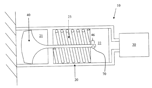
[00010] FIG. 1 is a breaching apparatus in accordance with embodiments;
[00011] FIG. 2 is a side view of an impact element of the breaching
apparatus in
accordance with embodiments;
[00012] FIG. 3 is an enlarged view of a portion of the impact element of
FIG. 2, which
is encircled by circle "A"; and
[00013] FIG. 4 is an enlarged view of another portion of the impact element
of FIG. 2,
which is encircled by circle "B".
[00014] The detailed description explains embodiments of the invention,
together with
advantages and features, by way of example with reference to the drawings.
DETAILED DESCRIPTION
[00015] With reference to FIG. 1, a controlled impact rescue tool (CIRT) 10
is
provided. The CIRT 10 is described in detail in US Patent No. 7,814,822, the
entire contents
of which are incorporated herein by reference. As a general matter, the CIRT
10 includes a
housing 20, a firing mechanism 30 and a single body impact element 40. The
housing 20 is
formed to define a tunnel 21 and includes a piston head 22 and a biasing unit
23. The piston
head 22 is movable through the tunnel 21 between a loaded position, at which
the piston head
22 is prepared to be fired, and a fired position, at which the piston head 22
is located
3
CA 02796486 2012-11-22
following a selective firing operation and subsequent impact. The biasing unit
23 is
configured to bias the piston head 22 to remain in the loaded position until a
selective firing
operation occurs. The biasing unit 23 may include an elastic element, such as
a spring, and
may further include a temporary lock that is engageable with the piston head
22 disposed in
the loaded position such that undesirable movement of the piston head 22 out
of the loaded
position may be prevented.
[00016] The firing mechanism 30 is responsible for the executing the selective
firing
operation against the bias of the biasing unit 23 and, where applicable, the
temporary lock.
The firing mechanism 30 may be operated by a pneumatic device, by internal
combustion of
high explosives within the tunnel 21 and/or by another similar configuration.
For purposes of
clarity and brevity, the case of the firing mechanism 30 being operable by
combustion of high
explosives within the tunnel 21 will be described herein but, as a general
matter, the firing
mechanism 30 is configured to apply force to the piston head 22 to overcome
the bias
provided by at least the biasing unit 23 to thereby move the piston head 22
at, in some cases,
high speed toward the fired position.
[00017] The single body impact element (the "impact element") 40 is
connectable to
the piston head 22 and is thereby drivable by the movement of the piston head
22 into an
external element, such as a concrete wall to be breached by the CIRT 10. Since
the
combustion of the high explosives within the tunnel 21 may provide substantial
kinetic
energy to the piston head 22, the impact element 40 is thereby drivable with
relative very
high velocity toward the external element.
[00018] Thus, the CIRT 10 is configured to harness energy released by heated
gases
produced by the firing mechanism 30 to push onto a rear face of the piston
head 22 such that
the piston head 22 and the impact element 40 move as a unit and acquire the
kinetic energy
required to produce damage on the external element (i.e., the concrete wall
intended to be
breached). Further, a shock wave may be produced in both the concrete wall and
the impact
element 40 during impact. The shock wave in the concrete wall is intended to
cause localized
damage and eventually produce a breach. The shock wave traveling through the
impact
element 40 may cause cyclical loading that could damage the impact element 40.
To this end,
4
CA 02796486 2012-11-22
the impact element 40 has been provided with features that result in longer
life, reduced
jamming and added reliability, as will be described below.
[00019] With reference to FIGS. 2-4, the impact element 40 includes a single
body 41,
which is drivable into the concrete wall. The single body 41 includes a head
42 and a shaft
43. The head 42 has a frusto-conical shape with a front end 421 that is
disposable in a leading
position and a rear end 422, which opposes the front end 421 and is disposable
in a trailing
position. The front end 421 may include a domed surface 4211 that produces the
shock wave
in the concrete wall. The radius of the dome surface 4211 can be optimized to
promote self-
alignment of the shaft 43 during operation to lengthen a lifetime of the shaft
43.
[00020] The shaft 43 has a first end 431, which is integrally coupled to the
rear end
422, a second end 432, which is opposite the first end 431 and a central
portion 433. The
central portion 433 is interposed between the first end 431 and the second end
432 and
includes an elongate member that extends along a longitudinal axis of the
impact element 40
and, in some cases, the tunnel 21 when the impact element 40 is disposed
therein. The central
portion 433 of the shaft 43 has a narrower diameter than the rear end 422. The
first end 431
of the shaft 43 has a trailing portion 4311 with a diameter that is similar to
that of the central
portion 433, a leading portion 4312 with a diameter that is similar to that of
the rear end 422
and a taper 4313 that extends from the trailing portion 4311 to the leading
portion 4312. The
taper 4313 may be curvilinear or gradual and, at least in the curvilinear
case, the taper 4313
may be characterized as a large radius transition between the central portion
433 and the head
42 and serves as a wave guide for shock waves to reduce stress concentration
points at the
interface between the first end 431 and the central portion 433 and to thereby
increase
structural stability.
[00021] In accordance with embodiments, the shaft 43 has a smooth exterior
surface
including exterior surface 44 of the first end 431 and exterior surface 45 of
the central portion
433. Exterior surfaces 44 and 45 are adjacent to one another and present a
smooth interface
from the substantially cylindrical surface of the central portion 433 to the
curvilinearly
tapered surface of the first end 431. As such, at least stress concentration
points are further
reduced.
5
CA 02796486 2012-11-22
1000221 In accordance with further embodiments, the trailing portion 4311 of
the first
end 431 of the shaft 43 may have the same diameter as the central portion 433
of the shaft 43
thereby providing the smooth interface. By contrast, the leading portion 4312
of the first end
431 of the shaft 43 may have a slightly narrower diameter than the rear end
422.
[00023] In accordance with further embodiments, the front end 421 has a
narrower
diameter than the rear end 422. That is, the head 42 is tapered from the rear
end 422 to the
front end 421. This improves an ability of the head 42 to be self cleaning and
reduces
potential for jamming of the head 42 during a firing operation that may result
from
mechanical interference and/or material accumulation in, for example, the
tunnel 21.
[000241 In accordance with further embodiments, the second end 432 of the
shaft 43 is
connectable with the piston head 22. This connection is provided such that the
second end
432 cannot be undesirably or otherwise non-selectively disengaged from the
piston head 22
under normal conditions. The connection also serves to define a joint 46
between the shaft 43
and the piston head 22 that is located remotely from the head 42. The second
end 432 of the
shaft 43 has an exterior surface 4321 with threading 50 formed thereon. The
threading 50
permits the impact element 40 to be threadably engageable with corresponding
threading
formed in a recess defined in the piston head 22. That is, the impact element
40 is formed
such that the head 42 and the shaft 43 are integrally coupled with one another
while the
threaded second end 432 for piston head 22 installation is placed remotely
from the impact
point. This placement of the threading 50 and the resulting definition of the
joint 46 being
remote from the head 22 may reduce potential for thread failure during at
least impact
instances.
[00025] With the threading 50 provided at the second end 432 of the shaft
43,
assembly of the impact element 40 may be performed as follows. In one
exemplary
embodiment, the impact element 40 and the piston head 22 can be threadably
engaged with
one another to form an impact element assembly, which is then configured to be
installed in
the housing 20. In an alternate exemplary embodiment, the piston head 22 is
installed in the
housing 20 and the impact element 40 is then connected to the piston head 22.
In this case, an
operator may handle the head 42 and may insert the shaft 43 into the housing
20 through the
tunnel 21 such that the shaft 43 eventually encounters the piston head 22. At
that point, the
6
CA 02796486 2012-11-22
operator rotates that impact element 40 about a longitudinal axis thereof to
threadably engage
the threading 50 at the second end 432 of the shaft 43 with the complementary
threading of
the piston head 22. As such, it is possible that multiple impact elements 40
can be relatively
easily connected to and disconnected from the piston head 22 during the
lifetime of the CIRT
without requiring removal of the piston head 22 from the housing 20.
[00026] It is to be understood that the operative connection between the shaft
43 and
the piston head 22 need not be provided by the threading 50 and the
complementary
threading of the piston head 22. In alternate embodiments, the operative
connection may be
provided by way of fasteners, snap-fittings, mechanical interlocks and/or
other similar
devices. In any case, the operative connection must be able to survive impact
instances
without disconnection failures and should be located remotely from the head
42. In addition,
although it is not required, the operative connection should be provided such
that the joint 46
is disposed along or radially proximate to the longitudinal axis of the shaft
43. As such, shock
waves from impact instances can be transmitted relatively evenly through the
joint 46 from
the shaft 43 to the piston head 22.
[00027] As shown in FIG. 3, the impact element 40 may further include a
locking unit
60 disposed at the second end 432 of the shaft 43. In accordance with
embodiments, the
locking unit 60 may be formed as a peripheral groove 61 extending about the
exterior surface
4321 at or near a base of the threading 50. Such a peripheral groove 61 may be
engageable
with a corresponding fastener, such as a rolled pin 70 (see FIG. 1), to permit
locking of the
shaft 43 to the piston head 22.
[00028] As shown in FIG. 4, the rear end 422 may include a shallow tapered
chamfer
80 to promote smooth operation of the CIRT 10 during piston head 22 resetting.
While a
diameter of a portion of the rear end 422 may be substantially similar to an
inner diameter of
the tunnel 21 in order to promote secure movement of the impact element 40
through the
tunnel, the shallow tapered chamfer 80 is characterized as having a reduced
diameter taper
with increasing axial distance from the front end 421. As such, mechanical
interference
during resetting of the impact element 40 or the piston head 22 can be reduced
or
substantially avoided. In particular, the shallow tapered chamfer 80 may
promote reinsertion
7
CA 02796486 2012-11-22
of the impact element 40 into the tunnel 21 and/or movement of the impact
element 40
through the tunnel 21.
[00029] While the invention has been described in detail in connection with
only a
limited number of embodiments, it should be readily understood that the
invention is not
limited to such disclosed embodiments. Rather, the invention can be modified
to incorporate
any number of variations, alterations, substitutions or equivalent
arrangements not heretofore
described, but which are commensurate with the spirit and scope of the
invention.
Additionally, while various embodiments of the invention have been described,
it is to be
understood that aspects of the invention may include only some of the
described
embodiments. Accordingly, the invention is not to be seen as limited by the
foregoing
description, but is only limited by the scope of the appended claims.
8