Note: Descriptions are shown in the official language in which they were submitted.
- 1 -
ACTUATION ELEMENT
The present invention relates to an actuation element in the form of a
pushbutton,
wherein the pushbutton includes at least one housing and at least one shaft
movable in translation in the housing.
It is known from the prior art to use pushbuttons which are connected to a
snap-in
mechanism or are formed by it. In this respect, this snap-in mechanism is
configured in the form of a dome and gives the user haptic feedback with
respect to
the actuation of the pushbutton. An advantage of this known actuation element
is
that it is signaled to the user by the named haptic feedback that the
actuation has
been carried out successfully; however, a disadvantage is the restricted
translational movement or movability of the pushbutton as well as the fact
that an
adaptation or change of the force with which the feedback is generated is not
possible in already known dome-shaped actuation elements based on a snap-in
mechanism.
It is therefore the underlying object of the invention to further develop an
actuation
element of the initially named kind such that the translational movement of
the
pushbutton can be configured as larger than in already known pushbuttons and
such that there is furthermore the possibility that the force with which the
feedback
to the user takes place can be adjusted.
This object is achieved by an actuation element described herein. Provision is
accordingly made that the housing and/or the shaft has at least one deformable
element and that the shaft and/or the housing has at least one activation
surface,
wherein the deformable element and the activation surface cooperate such that
the
deformable element exerts a counter-force on the shaft on the movement of the
shaft relative to the housing, said force being directed against the direction
of
movement of the shaft.
CA 2796609 2018-11-20
CA 02796609 2012-11-22
- 2 -
It is conceivable that the deformable element is elastically deformable. A
preferred
embodiment comprises the deformable element being formed by at least one
spring
or including at least one spring.
The named deformable element can extend over the full periphery or also only
partially peripherally about the named shaft.
Provision can furthermore be made that the activation surface is formed by a
section of the shaft which has an enlarged diameter with respect to the
adjacent
regions of the shaft and/or is formed by one or more projections which project
outwardly from the shaft. If the activation surface moves into the region of
the
deformable element, a counter-force perceivable for the user is exerted by the
deformable element on the pushbutton. This counter-force is recognized as a
tactile
feedback so that the user is ultimately informed that the actuation was
successfully
carried out by a switch or microswitch, for example.
Provision is made in a further embodiment that the activation surface and the
deformable element are configured such that the activation surface can be
moved
past the deformable element. It is thus conceivable, for example, that the
activation
surface and the deformable element are designed so that the activation surface
is
moved toward the deformable element, which is only possible while applying a
specific force, and so that the activation element and the deformable element
are
designed such that the activation surface can be moved beyond, i.e. past, the
deformable element.
It is conceivable in this respect that the shaft is designed such that, in the
position in
which the activation surface is moved past the deformable element, it is fixed
in this
position in at least one direction of movement by the deformable element. It
is
conceivable to fix the actuated pushbutton in the actuated position.
Provision is made in a further embodiment of the invention that the activation
surface is formed by one or more projections and/or by a thickened shaft
section
- 3 -
and that the shaft has a smaller diameter in the direction of movement of the
shaft
before and after the projections or the named shaft section than in the region
of the
projections or of the thickened section. Provision can alternatively or
additionally be
made that the total thickened shaft section and/or the projections is/are
designed
with mirror-symmetry relative to the plane of the thickening or of the
projections
which extends perpendicular to the shaft, i.e. it/they are the same or
substantially
the same with respect to the geometrical embodiment in the direction of
movement
of the shaft before and after the thickened shaft section or the
projection(s).
The present invention further relates to a system including at least one
actuation
element as described herein as well as to a switch, preferably a microswitch,
wherein the switch and the actuation element are arranged relative to one
another
such that the switch can be switched by the actuation element.
The present invention further relates to an aircraft having at least on
actuation
element as described herein and/or having at least one system in accordance
with
claim 9. It is conceivable to arrange the named actuation element and/or the
named
system in the cockpit of an aircraft, for example.
According to one aspect of the invention, there is provided an actuation
element in
the form of a pushbutton, wherein the pushbutton comprises at least one
housing
and at least one shaft movable in translation in the housing, wherein the
housing or
the shaft has at least one deformable element; and in that the shaft has at
least one
activation surface, wherein the activation surface is formed by a section of
the shaft
having an enlarged diameter with respect to the adjacent regions of the shaft
and/or
is formed by one or more projections which project outwardly from the shaft,
with
the deformable element and the activation surface cooperating with one another
such that the deformable element exerts a counter-force on the shaft on the
movement of the shaft relative to the housing, said force being directed
against the
direction of movement of the shaft.
CA 2796609 2018-11-20
- 3a -
Further advantages and particulars of the invention will be explained in
detail with
reference to an embodiment shown in the drawing. There are shown:
Figure 1: a longitudinal sectional representation through the actuation
element in
accordance with the invention before its actuation and the detail B in an
enlarged view; and
Figure 2: a longitudinal sectional representation through the actuation
element in
accordance with Figure 1 after its actuation and an enlarged view of
detail A.
CA 2796609 2018-11-20
CA 02796609 2012-11-22
=
- 4 -
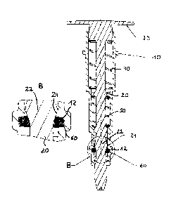
The stationary, that is not movable, housing of the actuation element in
accordance
with the present invention is designated in each case by the reference numeral
10
in Figures 1 and 2. The shaft 20 which has the actual actuation surface 30 for
the
user of the actuation element in its upper end region runs movable in
translation in
the housing 10.
As can further be seen from Figures 1 and 2, the shaft 20 is preloaded with
respect
to the housing 10 by means of the springs 40, 50 so that the shaft 20 is
preloaded
upwardly, relative to the housing 10, that is into the non-actuated position
in
accordance with Figure 1 or a force is exerted in this direction.
As can further be seen from Figures 1 and 2, the shaft 20 has a thickened
section
22 in its lower end region or in the lower end section of the housing 10. This
section
22 of the shaft 20 has a larger diameter than the sections of the shaft 20
which lie in
front of and behind the thickened section 22. An activation surface of the
shaft 22 is
designated by reference numeral 24 and is formed by or includes in the
embodiment shown here the region of largest diameter of the thickened section
22
of the shaft 20 and/or forms or includes the section of the shaft in which the
dimension of the shaft increases or decreases in the direction of thickness or
width.
The reference numeral 60 designates a spring or a spring band which is not
displaceable in the longitudinal direction of the housing 10 and in the
direction of
movement of the shaft 20, but is rather received in a groove 12 of the housing
as
can in particular be seen from the detailed representations B and A of Figures
1 and
2.
As can be seen from these detailed representations, this spring band 60 is
formed
by a helical spring 60 running around the shaft 20.
As can further be seen from Figures 1 and 2, the lower end region of the shaft
20 of
the actuation element projects out of the housing 10. A microswitch or the
like can
CA 02796609 2012-11-22
- 5 -
e.g. be arranged in this lower end region and is actuated when the pushbutton
or
the actuation element is actuated.
Figure 1 shows the state of the actuation element in accordance with the
invention
before its triggering or actuation by a user. As can be seen from this Figure,
the
activation surface 24 in this case is not in contact with the spring band 60,
but is
rather arranged in front of it in the direction of actuation of the shaft 20.
If now a
downward force is exerted on the actuation surface 30 and thus also on the
shaft
20 in accordance with Fig. 1, that is if a user wants to actuate the
pushbutton in
accordance with the invention, the shaft 20 is moved downwardly against the
force
of the springs 40, 50, which has the result that the activation surface 24
comes into
contact with the spring band 60. This has the result that the user, for
example, the
pilot, is given a haptic or tactile feedback which signals that the shaft 20
was moved
by a specific distance downwardly or relative to the housing. The spring band
60 is
elastically deformed by this downward movement due to the thickened section 22
of
the shaft 20 and at this moment exerts a counter-force on the hand of the
user. This
counter-force is perceived as tactile feedback so that the user knows that the
pushbutton was actuated.
If the pushbutton is fully depressed, as can be seen from Figure 2, the
activation
surface 24 moves past the elastically deformable spring band 60 and ultimately
lies
beneath the spring band 60, that is after it in the direction of movement, as
can be
seen from the detailed representation A. This means that during the movement
of
the shaft 20 in accordance with Figures 1 and 2 from the top to the bottom,
the
activation surface 24 initially lies in front of the elastically deformable
spring band
60, then at the level of the elastic, deformable spring band 60 and finally
lies after
the elastically deformable spring band 60.
In the position shown in Figure 2, the pushbutton is held in the position
shown by
the spring band 60 and a specific minimum force is required to move the shaft
20 or
the activation surface 24 in accordance with Figure 2 upwardly past the spring
band
60.
CA 02796609 2012-11-22
- 6 -
The moment at which the activation force 24 moves into the region of the
elastically
deformable spring band 60 and/or lies in its region and/or was already moved
beyond the elastic spring band 60 on the activation of the pushbutton, as can
be
seen from Figure 2, can give a haptic feedback or a tactile feedback to the
user
which signals to the user that the pushbutton has been properly actuated.
Unlike the snap-in domes known from the prior art, the present invention
allows a
substantially unlimited translational movability of the shaft 20 or of the
pushbutton.
A further advantage is that the force which is exerted by the deformed spring
or by
the deformed spring band 60 can be varied by the dimensions of the activation
surface 24 and/or of the spring or of the spring band 60. This force is
increased by
reducing the diameter of the activation surface 24.
It is possible by the variation of the position of the thickened section 22 or
activation
surface 24 to vary the position or the moment for a specific tactile feedback
to the
user. An aspect is thus conceivable in which the thickened section and/or
projections or the activation surface is/are not fixedly arranged at the shaft
20, as is
the case in the embodiment, but can rather be fixed at different positions
relative to
the shaft 20.
Finally, it is pointed out that the spring 60 or the movable element can also
be
arranged at the shaft and the activation surface or the thickened section or
the like
can be arranged at the housing. The above statements apply to such an
embodiment accordingly.