Note: Descriptions are shown in the official language in which they were submitted.
CA 02796687 2012-11-22
K- 10782CA
TITLE OF THE INVENTION
TERMINAL BOX
BACKGROUND OF THE INVENTION
FIELD OF THE INVENTION
The present invention relates to a terminal box having a terminal
board for connecting a tab of a solar cell panel to a power line.
DESCRIPTION OF THE RELATED ART
Generally, a solar cell module includes a plurality of solar cell
panels, with a terminal box being mounted on the back face of each solar cell
panel. This terminal box includes a terminal board for establishing
conduction between the tab of the solar cell panel and the external power
line. Hence, it is necessary for a portion of the terminal board to be
contacted to the tab of the solar cell panel.
Various arrangements are possible for the tab of the solar cell panel,
including a mode of arrangement in which the tab is mounted on the back
face of the solar cell panel (this will be referred to as "the first mode of
arrangement" hereinafter), another mode of arrangement in which the tab
is disposed inside the solar cell panel adjacent its back face (this will be
referred to as "the second mode arrangement" hereinafter). For contacting
the tab arranged as above with the terminal board, it is needed to ensure
that the terminal board projects from the main body of the terminal box.
On the other hand, if the amount of projection of the terminal box is
inappropriate, the terminal box may fail to contact the tab, thus resulting in
conduction failure. Conversely, if the projection amount is too large, this
may cause the terminal box to "float off', i.e. to detach from, the back face
of
the solar cell panel, thus forming a gap that allows intrusion of rainwater or
the like therethrough to the inside of the terminal box. For this reason,
1
CA 02796687 2012-11-22
appropriate setting is required for the projection amount of the terminal box
according to varied specifications of the solar cell panel.
However, the appropriate projection amount of terminal board
differs according to the specification of the solar cell panel. The
appropriate projection amount may differ according also to the difference of
the above-described mode of arrangement. For this reason, it is necessary
to adjust the projection amount of the terminal board according to the
specification of the solar cell panel employed. However, this adjustment is
troublesome and increases the cost of installment. Further, the terminal
box too needs to be configured to allow adjustment of the projection amount
of terminal board. This leads to increase in the manufacture cost of the
terminal box disadvantageously. Alternatively, it is conceivable to prepare
and employ terminal boards set with differing projection amounts. This is
also disadvantageous since it invites manufacture cost increase of the
terminal box again.
In an attempt to overcome the above problem, WO 2010/067466
discloses a terminal box configured such that spring-like characteristics is
provided to the leading end of the terminal board disposed substantially
parallel with a solar cell panel. Japanese Patent Application National
Transfer Publication No. 2011-503884 discloses a terminal box wherein an
elastic part is formed in an intermediate portion of the terminal board.
With these arrangements, reliable connection between the terminal board
and the tab can be ensured by the spring-like property characteristics of the
terminal board if a relatively large projection amount of the leading end of
the terminal board is set in advance. Further, as a pressing force resulting
from the connection is absorbed by the spring-like characteristics of the
leading end of the terminal board, the floating phenomenon of the terminal
box can be prevented also.
However, with the terminal boxes disclosed in WO 2010/067466 and
Japanese Patent Application National Transfer Publication No.
2011-503884, because an elastic part is formed at the leading end or
intermediate portion of the terminal board, the adjustability of the
projection amount of terminal board is not so large. Also, with the terminal
2
box disclosed in Japanese Patent Application National Transfer Publication
No. 2011-503884, since an elastic part is formed upwardly of a soldering
zone (a portion to be soldered to the tab of the terminal board), the elastic
part may hinder the soldering operation.
The present invention has been made in view of the above-described
state of the art and its object is to provide a terminal box that allows easy
adjustment of the projection amount of the terminal board.
SUMMARY OF THE INVENTION
According to one preferred embodiment of a terminal box relating to
the present invention, the terminal box comprising:
a box body forming a recessed portion; and
a terminal board accommodated within the recessed portion and
providing conduction between a tab of a solar cell panel and a power line;
wherein the terminal board includes a projecting portion
projecting from the box body toward the solar cell panel, and a spring
portion extended along a direction perpendicular to the projecting
direction of the projecting portion;
the projecting portion includes a contact portion for contacting the
tab of the solar cell panel;
the projecting portion is supported by a first-side end of the spring
portion;
the spring portion comprises a meander structure having a
plurality of folded portions in a plane having a normal line perpendicular
to both the projecting direction of the projecting portion and the extending
direction of the spring portion; and
the plurality of folded portions are arranged along the extending
direction of the spring portion.
3
CA 2796687 2018-10-04
With the above arrangement, a contact portion is formed at the
projecting portion which projects from the box body toward the solar cell
panel and this contact portion comes into contact with the tab of the solar
cell panel. Therefore, upon establishment of the contact between the
contact portion and the tab, a force is applied to the projecting portion in
its
retracting direction (the direction opposite the solar cell panel). As this
projecting portion is supported by the first-side end. of the spring portion
3a
CA 2796687 2018-10-04
CA 02796687 2012-11-22
disposed along the direction perpendicular to the projecting direction of the
projecting portion, the force applied to the projecting portion is transmitted
as a force along a direction bending the spring portion. Therefore, the
contact between the contact portion and the tab can be maintained
appropriately by the bending elasticity of the spring portion, thus
effectively
preventing the contact failure. Further, since this force applied to the
projecting portion is absorbed by the spring portion, the floating
phenomenon of the box body can be prevented. Moreover, even when the
projection amount of the projecting portion is small, the projection amount
can be adjusted largely, thanks to the bending elasticity of the spring
portion.
Further, with the above arrangement, the spring portion is
configured as a meander structure having a plurality of folded portions in a
plane having a normal line which is perpendicular to both the projecting
direction of the projecting portion and the extending direction of the spring
portion. With this, when viewed along the projecting direction of the
projecting portion, only the thickness portion of the spring portion is
visible.
That is, when viewed as above, the spring portion will show only as a linear
form. Therefore, the presence of the spring portion does not impair the
visibility of the contact portion, so that the soldering operation between
this
contact portion and the tab can be carried out easily.
According to a preferred embodiment of the terminal box relating to
the present invention, the terminal box further comprises a displacement
maintaining portion for maintaining a displaced state of the projecting
portion displaced along its projecting direction.
As described above, the projecting portion is supported to the end of
the spring portion and a force along the bending direction is applied to the
spring portion when the projecting portion (contact portion) comes into
contact with the tab. In this, if the amount of retraction of the projection
portion is large, a large elastic resilient force will be generated in the
spring
portion. This elastic resilient force is effective in the direction of
detaching
the terminal box from the solar cell panel (this direction will be referred to
as "the detaching direction"). However,
with the above-described
4
CA 02796687 2012-11-22
arrangement, the displacement maintaining portion maintains the
displaced state of the projecting portion displaced along the projecting
direction. Namely, the elastic resilience of the spring portion will be
supported by the displacement maintaining portion. With this, even when
a large elastic resilient force is generated in the spring portion, the force
in
the detaching direction applied to the terminal box can be reduced. In this
way, the reduction of the force in the detaching direction applied to the
terminal box can eliminate necessity of such an inconvenient operation of
keeping the terminal box pressed until adhesive agent applied for bonding
the terminal box to the solar cell panel is cured to provide appropriate
bonding force.
Such displacement maintaining portion can be realized with a
simple arrangement as follows. Namely, the displacement maintaining
portion can include an engaging pawl formed in one of the projecting portion
and the box body and an engaged portion formed in the other of the
projecting portion and the box body, the engaged portion being engageable
with the engaging pawl at one of a plurality of positions.
According to a further preferred embodiment of the terminal box
relating to the present invention, the terminal board includes a supported
portion to be supported to the box body, the supported portion being
provided at a second-side end opposite the first-side.
With the above-described arrangement, the supported portion will
serve as a "pivot" for supporting the force applied to the projecting portion.
Further, since the projecting portion is supported to the first-side end of
the
spring portion and the supported portion is provided at the second-side end,
a large distance can be secured between the pivot and the point of force or
leverage application. Therefore, a large force can be supported effectively.
According to a still further preferred embodiment of the terminal
box relating to the present invention, the terminal box further comprises a
pair of said spring portions and a support portion disposed between the
first-side ends of the pair of spring portions, and the projecting portion is
supported at an approximately center position of the support portion along
5
CA 02796687 2012-11-22
its disposing direction.
With the above-described arrangement, the projecting portion, in
particular, the contact portion, can be exposed from the space formed
between the pair of spring portions, so that the soldering operation between
the contact portion and the tab can be further facilitated. Moreover, since
the projecting portion is supported by the pair of spring portions via the
support portion, the projecting portion can be supported in a stable manner.
According to a still further preferred embodiment of the terminal
box relating to the present invention, the terminal board has an
approximately rectangular shape having four sides, and the spring portions
are formed in the two sides adjacent the side along the first-side, and an
external connecting portion for connecting the power line is formed in the
second-side.
With the above-described arrangement, the projecting portion and
the external connecting portion are formed in the sides opposite each other.
This arrangement makes it difficult for the force applied to the projecting
portion to be transmitted to the external connecting portion. Thus, when a
force is applied to the connecting portion between the external connecting
portion and the power line, it is possible to prevent deterioration of the
connection conditions therebetween.
BRIEF DESCRIPTION OF THE DRAWINGS
[Fig. 1] is a perspective view showing a terminal box of the present
invention as viewed from its upper side,
[Fig. 21 is a perspective view showing the terminal box of the
present invention as viewed from its lower side,
[Fig. 3] is an exploded perspective view of the terminal box of the
present invention,
[Fig. 4] is an exploded perspective view of the terminal box of the
present invention,
[Fig. 5] is a section view of the terminal box of the present invention,
[Fig. 6] is a section view showing the terminal box of the present
6
CA 02796687 2012-11-22
invention at the time of its mounting,
[Fig. 71 is a section view of the terminal box of the present invention,
and
[Fig. 81 is a development view of the terminal board of the present
invention.
DETAILED DESCRIPTION OF THE PREFERRED EMBODIMENT
Next, with reference to the accompanying drawings, an embodiment
of the terminal box relating to the present invention will be described. Figs.
1 and 2 are perspective views showing the terminal box according to the
instant embodiment as viewed from its upper side and lower side,
respectively. Figs. 3 and 4 are exploded perspective views showing the
terminal box according to the instant embodiment as viewed from its upper
side and lower side, respectively. As shown in these figures, the terminal
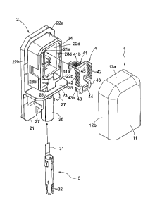
box includes, as its principal components, an upper body portion 1, a lower
body portion 2 ("a box main body"), a pin 3, and a terminal board 4. It
should be noted that these figures show only those portions of the
above-described components of the terminal box which relate in particular
to the present invention.
The upper body portion 1 includes an upper wall 11, four side walls
12a, 12b, 12c, 12d extending vertically from the upper wall 11. Therefore,
the upper body portion 11 has an approximately box-like shape having a
bottom opening. The side walls 12a, 12b and 12d respectively have a
rectangular shape, whereas the side wall 12c has an arch-like shape
defining a hole 13.
On the other hand, the lower body portion 2 includes a lower wall 21
and four side walls 22a, 22b, 22c, 22d extending vertically from the lower
wall 21. On the inner sides of the side walls 22b, 22c, 22d, there are formed
inner walls 28b, 28c, 28d extending vertically and in parallel with the
respective side walls. The space surrounded by the side wall 22a and the
inner walls 28b, 28c, 28d defines a recessed portion 24 for accommodating
the terminal board 4. At the portion of the lower wall 21 corresponding to
the bottom of the recessed portion 24, a hole 21a is formed. Further, at a
7
CA 02796687 2012-11-22
predetermined distance from the side wall 22c, a vertical wall 23 extends
vertically from the lower wall 21 and between the side wall 22c and the
vertical wall 23, there is formed a connecting portion 25 having an
approximately cylindrical shape.
Then, when the upper body portion 1 is engaged over the lower body
portion 2 constructed as above, the recessed portion 24 of the lower body
portion 2 can be sealed. More particularly, the side walls 12a, 12b, 12c, 12d.
of the upper body portion 1 come into contact respectively with the side
walls 22a, 22b, 22c, 22d of the lower body portion 2 from the outside thereof.
In the course of this, the outer face of the side wall 12c of the upper body
portion 1 comes into contact with the face (this will be referred to as the
"inner face" hereinafter) of the vertical wall 23 of the lower body portion 2
which face defines the recessed portion 24. Further, into the hole 13
defined in the side wall 12c of the upper body portion 1, the connecting
portion 25 of the lower body portion 2 will come into engagement. In this
way, the recessed portion 24 of the lower body portion 2 can be sealed.
The face (this will be referred to as the "outer face" hereinafter) on
the side opposite (this side will be referred to as the "outer side"
hereinafter)
the side of the vertical wall 23 defining the recessed portion 24 forms a
cylindrical portion 26. Into this cylindrical portion 26, there is inserted
the
pin 3111 which the power line is inserted. Further, from the vertical wall 23
toward the outer side, a pair of retaining pawls 27 extend.
The pin 3 comprises a conductive member having an approximately
cylindrical shape. Into this pin 3, a conductive member connected to the
power line will be inserted. With this, electric conduction is established
between the power line and the pin 3. At the terminal end of the pin 3 to
be inserted into the terminal box, there is provided a tongue-like portion 31
to be connected to the terminal board 4. Therefore, the pin 3 will be
inserted such that the tongue-like portion 31 is exposed to the recessed
portion 24 through the cylindrical portion 26 and the connecting portion 25
(see Fig. 5 and Fig. 6). Incidentally, a different arrangement may be
provided wherein the pin 3 is connected to a power line having its
conductive wire exposed with stripping of its outer sheath.
8
CA 02796687 2012-11-22
Further, at the terminal end of the pin 3 opposite the side having
the tongue-like portion, there is formed a retaining portion 32 for
maintaining the conductive member connected to the power line. In this
retaining portion 32, there are formed a plurality of slits extending along
the axial direction for forming an inner diameter smaller than that of the
rest.
The terminal board 4 is formed of a conductive material and
includes a projecting portion 41 projecting downwards, a pair of spring
portions 42 supporting the projecting portion 41, a pair of supported
portions 43 supported by the lower body portion 2 and an external
connecting portion 44 on which the tongue-like portion 31 of the pin 3 is to
be placed. Each spring portion 42 supports the projecting portion 41 at the
first-side end thereof and supports the supported portion 43 at the
second-side end opposite the first-side.
Figs. 5 and 6 are section views of the terminal box according to the
instant embodiment taken along a section line extending along the inner
walls 28b, 28d (this direction will be referred to as the "fore/aft direction"
hereinafter). As shown, the spring portions 42 are accommodated in the
recessed portion 24 of the lower body portion 2 in such a manner that the
longitudinal direction thereof is aligned with the fore/aft direction of the
terminal box. In this, the length of the projecting portion 41 is set such
that this projecting portion 41 may project from the lower wall 21 of the
lower body portion 2 through the hole 21a of the lower body portion 2.
After the terminal board 4 is accommodated in the recessed portion 24 and a
soldering is provided between the connecting portion of the projecting
portion and the tab of the solar cell panel as will be described later, an
amount of filling material will be charged into the recessed portion 24, thus
sealing this recessed portion 24.
The projecting-side terminal end of the projecting portion 41 is bent
inwards at an approximately right angle, thus forming a contacting portion
41a to contact and be connected to the tab of the solar cell panel. Hence,
the terminal box will be mounted to the back face of the solar cell panel with
9
CA 02796687 2012-11-22
the tab and the connecting portion 41a being in contact with each other,
these components will be soldered to each other. With this, electrical
conduction will be established between the solar cell panel and the terminal
board 4.
As described above, the spring portions 42 are accommodated in the
recessed portion 24 with their longitudinal direction being aligned with the
fore/aft direction. And, between the side wall 22a side ends of the pair of
spring portions 42, there is provided a supporting portion 45 that extends in
the direction along the side wall 22a (this direction will be referred to as
the
"right/left direction" hereinafter). The projecting portion 41 is supported at
the approximately right/left center of this supporting portion 45. With use
of such arrangement as above, the projecting portion 41 can be supported in
a stable manner.
Further, at the ends of the spring portions 42 opposite the sides
provided with the projecting portion 41, there are provided a pair of
supported portions 43. These supported portions 43 respectively define
engaging holes 43a in which engaging projections (not shown) formed in the
inner wall face of the recessed portion24 of the lower body portion 2 can
engage. With this engagement, the terminal board 4 is supported to the
lower body portion 2.
Between the pair of supported portions 43, there is formed the
external connecting portion 44 which is substantially flat. As described
hereinbefore, on this external connecting portion 44, the tongue-like portion
31 of the pin 31 will be placed and then the external connecting portion 44
and the tongue-like portion 31 will be soldered to each other. With this, via
the pin 3, conduction is established between the terminal board 4 and the
power line, thus establishing electric conduction between the solar cell panel
and the power line.
Each spring portion 42 has a meandering (zigzagging) structure
having a plurality of folded portions in the plane extending along the inner
faces of the side walls 22b, 22d of the lower body portion 2. Therefore, the
spring portion 42 has bending elasticity in the direction along the projecting
CA 02796687 2012-11-22
direction of the projecting portion 41 (this direction will be referred to as
the
"projecting/retracting direction", the increasing direction will be referred
to
as the "projecting direction" and the decreasing direction will be referred to
as the "retracting direction", respectively, hereinafter). This bending
elasticity serves to facilitate adjustment of the projection amount of the
projecting portion 41.
Further, when the terminal box is mounted on the back face of the
solar cell panel, a reaction force from the solar cell panel will be applied
to
the projecting portion 41. In this, this reaction force can be absorbed by the
bending elasticity of the spring portion 42. Thus, even when a significant
reaction force along the retracting direction is applied to the projecting
portion 41, as this reaction force is absorbed by the bending elasticity of
the
spring portion 42, the floating phenomenon of the terminal box can be
prevented by this reaction force.
Conversely, even when there exists shortage in the projection
amount of the projecting portion 41, as the bending elasticity of the spring
portion 42 allows large adjustment of the projection amount of the
projecting portion 41, reliable contact between the contacting portion 41a
and the tab can be realized, thus effectively preventing occurrence of contact
failure.
As described hereinbefore, the terminal board 4 is supported to the
lower body portion 2 via the supported portions 43 and the projecting
portion 41 and the supported portions 43 are provided on the opposed ends
of the spring portions 42. With this arrangement, a large distance can be
secured between the point of force application of the reaction force applied
from the solar cell panel to the terminal board 4 and the pivot point, thus
increasing the reaction force that can be supported by the spring portions
42.
Each spring portion 42 is formed of a plate-like member having a
face extending along the inner face of the side walls 22c, 22d of the lower
body portion 2. Hence, when the terminal board 4 is viewed from the above,
a space is formed between the pair of spring portions 42 as shown in the
11
CA 02796687 2012-11-22
section view of Fig. 7 along the section line parallel with the lower wall,
and
through this space, the contacting portion 41a can be seen or exposed.
Moreover, as the plate-like spring portions 42 are disposed in opposition to
each other, the above space can be formed large. Therefore, through this
space formed between the pair of spring portions 42, the contacting portion
41a and the tab can be soldered to each other. In this way, the soldering
work can be carried out with ease.
As described hereinbefore, with the bending elasticity of the spring
portions 42, the reaction force applied to the projecting portion 41 from the
solar cell panel can be supported effectively. However, if a significant
bending force is applied to the spring portions 42, the resulting elastic
resilient forces of the spring portions 42 will be large, and these forces
will
act as forces tending to detach the terminal box from the solar cell panel, so
that the assembling of the terminal box may be hindered.
In order to avoid the above, the terminal box according to the
present invention includes a displacement maintaining portion for
maintaining a displaced state of the projecting portion 41 displaced along its
projecting/retracting direction. In the instant embodiment, this
displacement maintaining portion consists essentially of a ladder-like
portion 41b (an example of "engaged portion" in the invention) formed in the
projecting portion 41, and an engaging pawl 21b formed in the inner wall
face of the hole 21a defined in the lower body portion 2. More particularly,
the ladder-like portion 41b includes a plurality of bar-like members
extending along the right/left direction, to each one of the bar-like members,
the engaging pawl 21b is engageable.
As shown in Fig. 5, when the projecting portion 41 is not displaced,
the engaging pawl 21b is located upwardly of the plurality of bar-like
members of the ladder-like portion 41b, not engaging any of these bar-like
members. On the other hand, as shown in Fig. 6, when the projecting
portion 41 is displaced in the retracting direction, this will bring the
engaging pawl 21b to a position downwardly of one of the bar-like members.
In this, the elastic resilient force of the spring portion 42 will be applied
to
the projecting portion 41, but, the engagement between the engaging pawl
12
CA 02796687 2012-11-22
21b and one bar-like member prevents the displacement of the projecting
portion 41 in the projecting direction.
As described above, as the terminal box is provided with the
displacement maintaining portion for maintaining the displaced state of the
projecting portion 41, when the terminal box is fixed and bonded to the back
face of the solar cell panel, the floating phenomenon of the terminal box can
be effectively prevented, so that the reliability of bonding can be increased.
Fig. 8 is a development view of the terminal board 4. As may be
apparent from this figure, the terminal board 4 is formed by punching and
pressing of a single fiat sheet of conductive material. In this way, the
projecting portion 41 is formed between the pair of spring portions 42. The
amount of material needed for this terminal board 4 can be small and the
amount of material to be wasted can be correspondingly reduced also.
Moreover, a mold for use in the punching or pressing can be small. As
these all contribute to reduction of manufacturing cost, they are
advantageous.
[Other Embodiments]
(1) In the foregoing embodiment, the engaging pawl 21b is formed
in the lower body portion 2 and the ladder-like portion 41b is formed in the
projecting portion 41 of the terminal board. Instead, the ladder-like
portion can be formed in the lower body portion 2 and the engaging pawl
can be formed in the projecting portion of the terminal board. Further
alternatively, the engaged portion can be embodied not as a ladder-like
portion, but may be embodied in any other form.
(2) In the foregoing embodiment, the displacement maintaining
portion is configured to check or hinder displacement of the projecting
portion 41 in the projecting direction. Conversely, the displacement
maintaining portion can be configured to check or hinder displacement of
the projecting portion 41 in the retracting direction. With this alternative
configuration of the displacement maintaining portion, when adjustment is
made to increase the projection amount of the projecting portion 41,
13
CA 02796687 2012-11-22
inadvertent retraction of the projecting portion 41 can be effectively
prevented, so that contact failure between the contact portion 41a and the
tab can be avoided.
14