Note: Descriptions are shown in the official language in which they were submitted.
CA 02796742 2012-10-17
WO 2011/131780 PCT/EP2011/056479
CODED FERRULE FOR A DRUG DELIVERY DEVICE
Field of the Disclosure
Specific embodiments of this disclosure relate to reservoirs, particularly
reservoirs
containing a medicament. More particularly, the present application is
generally directed
to a coded ferrule for use with a reservoir and a reservoir holder so as to
prevent
unwanted reservoir cross use. As just one example, such medicament reservoirs
may
comprise an ampoule, a cartridge, a vial, or a pouch, and may be used with a
medical
delivery device. Exemplary medical delivery devices include, but are not
limited to,
syringes, pen-type injection syringes, pumps, inhalers, or other similar
injection or
infusing devices that require at least one reservoir containing at least one
medicament.
Background
Medicament reservoirs such as ampoules, cartridges, or vials are generally
known.
Such reservoirs are especially used for medicaments that may be self
administered by a
patient.
The term "medicament", as used herein, preferably means a pharmaceutical
formulation
containing at least one pharmaceutically active compound,
wherein in one embodiment the pharmaceutically active compound has a molecular
weight up to 1500 Da and/or is a peptide, a proteine, a polysaccharide, a
vaccine, a
DNA, a RNA, an enzyme, an antibody, a hormone or an oligonucleotide, or a
mixture of
the above-mentioned pharmaceutically active compound, wherein in a further
embodiment the pharmaceutically active compound is useful for the treatment
and/or
prophylaxis of diabetes mellitus or complications associated with diabetes
mellitus such
as diabetic retinopathy, thromboembolism disorders such as deep vein or
pulmonary
thromboembolism, acute coronary syndrome (ACS), angina, myocardial infarction,
cancer, macular degeneration, inflammation, hay fever, atherosclerosis and/or
rheumatoid arthritis,
CA 02796742 2012-10-17
WO 2011/131780 PCT/EP2011/056479
2
wherein in a further embodiment the pharmaceutically active compound comprises
at
least one peptide for the treatment and/or prophylaxis of diabetes mellitus or
complications associated with diabetes mellitus such as diabetic retinopathy,
wherein in a further embodiment the pharmaceutically active compound comprises
at
least one human insulin or a human insulin analogue or derivative, glucagon-
like
peptide (GLP-1) or an analogue or derivative thereof, or exedin-3 or exedin-4
or an
analogue or derivative of exedin-3 or exedin-4.
Insulin analogues are for example Gly(A21), Arg(B31), Arg(B32) human insulin;
Lys(B3), Glu(B29) human insulin; Lys(B28), Pro(B29) human insulin; Asp(B28)
human
insulin; human insulin, wherein proline in position B28 is replaced by Asp,
Lys, Leu, Val
or Ala and wherein in position B29 Lys may be replaced by Pro; Ala(B26) human
insulin; Des(B28-B30) human insulin; Des(B27) human insulin and Des(B30) human
insulin.
Insulin derivates are for example B29-N-myristoyl-des(B30) human insulin; B29-
N-
palmitoyl-des(B30) human insulin; B29-N-myristoyl human insulin; B29-N-
palmitoyl
human insulin; B28-N-myristoyl LysB28ProB29 human insulin; B28-N-palmitoyl-
LysB28ProB29 human insulin; B30-N-myristoyl-ThrB29LysB30 human insulin; B30-N-
palmitoyl- ThrB29LysB30 human insulin; B29-N-(N-palmitoyl-Y-glutamyl)-des(B30)
human insulin; B29-N-(N-lithocholyl-Y-glutamyl)-des(B30) human insulin; B29-N-
(w-
carboxyheptadecanoyl)-des(B30) human insulin and B29-N-(w-
carboxyheptadecanoyl)
human insulin.
Exendin-4 for example means Exendin-4(1-39), a peptide of the sequence H-His-
Gly-
Glu-Gly-Thr-Phe-Thr-Ser-Asp-Leu-Ser-Lys-Gln-Met-Glu-Glu-Glu-Ala-Val-Arg-Leu-
Phe-
Ile-Glu-Trp-Leu-Lys-Asn-Gly-Gly-Pro-Ser-Ser-Gly-Ala-Pro-Pro-Pro-Ser-N H2.
Exendin-4 derivatives are for example selected from the following list of
compounds:
H-(Lys)4-des Pro36, des Pro37 Exendin-4(1-39)-NH2,
CA 02796742 2012-10-17
WO 2011/131780 PCT/EP2011/056479
3
H-(Lys)5-des Pro36, des Pro37 Exendin-4(1-39)-NH2,
des Pro36 [Asp28] Exendin-4(1-39),
des Pro36 [IsoAsp28] Exendin-4(1-39),
des Pro36 [Met(O)14, Asp28] Exendin-4(1-39),
des Pro36 [Met(O)14, IsoAsp28] Exendin-4(1-39),
des Pro36 [Trp(02)25, Asp28] Exendin-4(1-39),
des Pro36 [Trp(02)25, IsoAsp28] Exendin-4(1-39),
des Pro36 [Met(O)14 Trp(02)25, Asp28] Exendin-4(1-39),
des Pro36 [Met(O)14 Trp(02)25, IsoAsp28] Exendin-4(1-39); or
des Pro36 [Asp28] Exendin-4(1-39),
des Pro36 [IsoAsp28] Exendin-4(1-39),
des Pro36 [Met(O)14, Asp28] Exendin-4(1-39),
des Pro36 [Met(O)14, IsoAsp28] Exendin-4(1-39),
des Pro36 [Trp(02)25, Asp28] Exendin-4(1-39),
des Pro36 [Trp(02)25, IsoAsp28] Exendin-4(1-39),
des Pro36 [Met(O)14 Trp(02)25, Asp28] Exendin-4(1-39),
des Pro36 [Met(O)14 Trp(02)25, IsoAsp28] Exendin-4(1-39),
wherein the group -Lys6-NH2 may be bound to the C-terminus of the Exendin-4
derivative;
or an Exendin-4 derivative of the sequence
H-(Lys)6-des Pro36 [Asp28] Exendin-4(1-39)-Lys6-NH2,
des Asp28 Pro36, Pro37, Pro38Exendin-4(1-39)-NH2,
H-(Lys)6-des Pro36, Pro38 [Asp28] Exendin-4(1-39)-NH2,
H-Asn-(GIu)5des Pro36, Pro37, Pro38 [Asp28] Exendin-4(1-39)-NH2,
des Pro36, Pro37, Pro38 [Asp28] Exendin-4(1-39)-(Lys)6-NH2,
H-(Lys)6-des Pro36, Pro37, Pro38 [Asp28] Exendin-4(1-39)-(Lys)6-NH2,
H-Asn-(GIu)5-des Pro36, Pro37, Pro38 [Asp28] Exendin-4(1-39)-(Lys)6-NH2,
H-(Lys)6-des Pro36 [Trp(02)25, Asp28] Exendin-4(1-39)-Lys6-NH2,
H-des Asp28 Pro36, Pro37, Pro38 [Trp(02)25] Exendin-4(1-39)-NH2,
H-(Lys)6-des Pro36, Pro37, Pro38 [Trp(02)25, Asp28] Exendin-4(1-39)-NH2,
H-Asn-(GIu)5-des Pro36, Pro37, Pro38 [Trp(02)25, Asp28] Exendin-4(1-39)-NH2,
des Pro36, Pro37, Pro38 [Trp(02)25, Asp28] Exendin-4(1-39)-(Lys)6-NH2,
CA 02796742 2012-10-17
WO 2011/131780 PCT/EP2011/056479
4
H-(Lys)6-des Pro36, Pro37, Pro38 [Trp(02)25, Asp28] Exendin-4(1-39)-(Lys)6-
NH2,
H-Asn-(Glu)5-des Pro36, Pro37, Pro38 [Trp(02)25, Asp28] Exendin-4(1-39)-(Lys)6-
NH2,
H-(Lys)6-des Pro36 [Met(O)14, Asp28] Exendin-4(1-39)-Lys6-NH2,
des Met(O)14 Asp28 Pro36, Pro37, Pro38 Exendin-4(1-39)-NH2,
H-(Lys)6-desPro36, Pro37, Pro38 [Met(O)14, Asp28] Exendin-4(1-39)-NH2,
H-Asn-(Glu)5-des Pro36, Pro37, Pro38 [Met(O)14, Asp28] Exendin-4(1-39)-NH2,
des Pro36, Pro37, Pro38 [Met(O)14, Asp28] Exendin-4(1-39)-(Lys)6-NH2,
H-(Lys)6-des Pro36, Pro37, Pro38 [Met(O)14, Asp28] Exendin-4(1-39)-(Lys)6-NH2,
H-Asn-(Glu)5 des Pro36, Pro37, Pro38 [Met(O)14, Asp28] Exendin-4(1-39)-(Lys)6-
NH2,
H-Lys6-des Pro36 [Met(O)14, Trp(02)25, Asp28] Exendin-4(1-39)-Lys6-NH2,
H-des Asp28 Pro36, Pro37, Pro38 [Met(O)14, Trp(02)25] Exendin-4(1-39)-NH2,
H-(Lys)6-des Pro36, Pro37, Pro38 [Met(O)14, Asp28] Exendin-4(1-39)-NH2,
H-Asn-(Glu)5-des Pro36, Pro37, Pro38 [Met(O)14, Trp(02)25, Asp28] Exendin-4(1-
39)-
NH2,
des Pro36, Pro37, Pro38 [Met(O)14, Trp(02)25, Asp28] Exendin-4(1-39)-(Lys)6-
NH2,
H-(Lys)6-des Pro36, Pro37, Pro38 [Met(O)14, Trp(02)25, Asp28] Exendin-4(S1-39)-
(Lys)6-NH2,
H-Asn-(Glu)5-des Pro36, Pro37, Pro38 [Met(O)14, Trp(02)25, Asp28] Exendin-4(1-
39)-
(Lys)6-NH2;
or a pharmaceutically acceptable salt or solvate of any one of the afore-
mentioned
Exedin-4 derivative.
Hormones are for example hypophysis hormones or hypothalamus hormones or
regulatory active peptides and their antagonists as listed in Rote Liste, ed.
2008,
Chapter 50, such as Gonadotropine (Follitropin, Lutropin, Choriongonadotropin,
Menotropin), Somatropine (Somatropin), Desmopressin, Terlipressin,
Gonadorelin,
Triptorelin, Leuprorelin, Buserelin, Nafarelin, Goserelin.
A polysaccharide is for example a glucosaminoglycane, a hyaluronic acid, a
heparin, a
low molecular weight heparin or an ultra low molecular weight heparin or a
derivative
thereof, or a sulphated, e.g. a poly-sulphated form of the above-mentioned
CA 02796742 2012-10-17
WO 2011/131780 PCT/EP2011/056479
polysaccharides, and/or a pharmaceutically acceptable salt thereof. An example
of a
pharmaceutically acceptable salt of a poly-sulphated low molecular weight
heparin is
enoxaparin sodium.
Pharmaceutically acceptable salts are for example acid addition salts and
basic salts.
5 Acid addition salts are e.g. HCI or HBr salts. Basic salts are e.g. salts
having a cation
selected from alkali or alkaline, e.g. Na+, or K+, or Ca2+, or an ammonium ion
N+(R1)(R2)(R3)(R4), wherein R1 to R4 independently of each other mean:
hydrogen,
an optionally substituted C1-C6-alkyl group, an optionally substituted C2-C6-
alkenyl
group, an optionally substituted C6-C10-aryl group, or an optionally
substituted C6-C10-
heteroaryl group. Further examples of pharmaceutically acceptable salts are
described
in "Remington's Pharmaceutical Sciences" 17. ed. Alfonso R. Gennaro (Ed.),
Mark
Publishing Company, Easton, Pa., U.S.A., 1985 and in Encyclopedia of
Pharmaceutical
Technology.
Pharmaceutically acceptable solvates are for example hydrates.
For example, with respect to insulin, a patient suffering from diabetes may
require a
certain amount of insulin to either be injected via a pen-type injection
syringe or infused
via a pump. With respect to certain known reusable pen-type drug delivery
devices, a
patient loads a cartridge containing the insulin into a proximal end of a
cartridge holder.
After the cartridge has been correctly loaded, the user may then be called
upon to
select a dose of medicament. Multiple doses may be dosed from the cartridge.
Where
the drug delivery device comprises a reusable device, once the cartridge is
empty, the
cartridge holder may be disconnected from the drug delivery device and the
empty
cartridge may be removed and replaced with a new cartridge. Most suppliers of
such
cartridges recommend the user to dispose of the empty cartridges properly.
Where the
drug delivery device comprises a disposable device, once the cartridge is
empty, the
user may be recommended to dispose of the entire device.
Such known self administration systems requiring the removal and reloading of
empty
cartridges have certain limitations. For example, in certain generally known
systems, a
user simply loads a new cartridge into the delivery system without the drug
delivery
CA 02796742 2012-10-17
WO 2011/131780 PCT/EP2011/056479
6
device or without the cartridge having any mechanism of preventing cross-use
of an
incorrect cartridge. That is, the drug delivery device does not have a
mechanism for
determining whether the medicament contained in the cartridge is indeed the
correct
type of medicament to be administered by the patient. Alternatively, certain
known drug
delivery devices do not present a mechanism for determining whether the
correct type
of medicament within the cartridge should be used with that particular drug
delivery
system. This potential problem could be exacerbated given that certain elderly
patients,
such as those suffering from diabetes, may have limited manual dexterity.
Identifying an
incorrect medicament is quite important, since the administration of a
potentially
incorrect dose of a medicament such as a short-acting insulin in lieu of a
long-acting
insulin could result in injury or even death.
Some drug delivery devices or systems may use a color coding scheme to assist
a user
or care giver in selecting the correct cartridge to be used with a drug
delivery device.
However, such color coding schemes may pose challenges to certain users,
especially
those users suffering from poor eyesight or color blindness: a situation that
can be quite
prevalent in patients suffering from diabetes.
Another concern that may arise with such disposable cartridges is that these
cartridges
are manufactured in essentially standard sizes and are manufactured to comply
with
certain recognized local and international standards. Consequently, such
cartridges are
typically supplied in standard sized cartridges (e.g. 3 ml cartridges).
Therefore, there
may be a variety of cartridges supplied by a number of different suppliers and
containing a different medicament but they may fit a single drug delivery
device. As just
one example, a first cartridge containing a first medicament from a first
supplier may fit
a medical delivery device provided by a second supplier. As such, a user might
be able
to load and then dispense an incorrect medicament (such as a rapid or basal
type of
insulin) into a drug delivery device without being aware that the medical
delivery device
was perhaps neither designed nor intended to be used with such a cartridge.
As such, there is a growing desire from users, health care providers, care
givers,
regulatory entities, and medical device suppliers to reduce the potential risk
of a user
CA 02796742 2012-10-17
WO 2011/131780 PCT/EP2011/056479
7
loading an incorrect drug type into a drug delivery device. There is also,
therefore, a
desire to reduce the risk of dispensing an incorrect medicament (or the wrong
concentration of the medicament) from such a drug delivery device.
There is, therefore, a general need to physically dedicate or mechanically
code a
cartridge to its drug type and design an injection device that only accepts or
works with
the dedication or coded features provided on or with the cartridge so as to
prevent
unwanted cartridge cross use. Similarly, there is also a general need for a
dedicated
cartridge that may allow the medical delivery device to be used with only an
authorized
cartridge containing a specific medicament while also preventing undesired
cartridge
cross-use.
There is also a general need to provide a dedicated cartridge that is
difficult to tamper
with so that the cartridge may not be compromised in that the cartridge can be
used
with an unauthorized drug or drug delivery device. Because such cartridges may
be
difficult to tamper with, they may also reduce the risk of counterfeiting:
i.e. making it
more difficult for counterfeiters to provide unregulated counterfeit
medicament carrying
products.
Problem to be solved
The problem to be solved by the present disclosure is to provide a ferrule, a
cartridge
and a drug delivery device which contribute to increasing the safety of the
user.
SUMMARY
One aspect relates to a ferrule for use with a cartridge. The ferrule may
comprise a
main body. Said main body may have a length generally equivalent to a length
of a
tubular barrel of said cartridge. The main body may define a bore. The bore
may extend
between a proximal end and a distal end of the main body. The bore may be
configured
for receiving the cartridge. A side wall may extend from the proximal end and
the distal
end. The ferrule may comprise a pass through. The pass through may be defined
by the
distal end. The ferrule may comprise at least one, preferably two ore more,
coding
features. The at least one coding feature may be provided along at least a
portion of the
main body. The coding feature may cooperate with a corresponding coding
feature
CA 02796742 2012-10-17
WO 2011/131780 PCT/EP2011/056479
8
provided by a drug delivery device. In particular, said coding feature may
cooperate with
a corresponding coding feature provided by a cartridge holder of said drug
delivery
device. Additionally or alternatively, said coding feature may cooperate with
a
corresponding coding feature provided by a dose setting member of said drug
delivery
device.
According to an embodiment, the ferrule comprises a molded ferrule.
Alternatively, the
ferrule may comprise a metallic ferrule. Said ferrule may comprise a heat
shrink
material.
According to an embodiment, said coding feature is provided along an end face
of said
main body. Alternatively, the coding feature may be provided along a side wall
of said
main body. In particular, said coding feature may extend from said proximal
end to said
distal end.
According to an embodiment, said coding feature comprises a plurality of
indentations.
The plurality of indentations may be provided on the end face of said main
body.
Alternatively, said coding feature comprises a plurality of protrusions. The
plurality of
protrusions may be provided on the end face of said main body.
According to an embodiment, said ferrule further comprises a, preferably,
releasable
coupling for mounting a needle assembly. Said releasable coupling may comprise
a
thread.
According to an embodiment, said coding feature comprises slots. The slots may
be
provided along said side wall of said main body. Said slots may extend from
said
proximal end to said distal end of said main body.
According to an embodiment, said coding feature comprises a vertical wall of
said main
body. Said vertical wall may comprise a varying thickness. Said vertical wall
comprising
said varying thickness may comprise at least one flat surface.
CA 02796742 2012-10-17
WO 2011/131780 PCT/EP2011/056479
9
According to an embodiment, the ferrule may comprise a flange, preferably an
inner
flange. Said coding feature may be provided near the inner flange of said
ferrule.
According to an embodiment, said corresponding coding feature of said drug
delivery
device is provided near a distal end of a cartridge holder of said drug
delivery device.
According to an embodiment, said coding feature prevents said cartridge from
rotating
within said cartridge holder. Additionally or alternatively, said coding
feature may
prevent said ferrule from rotating with respect to said cartridge.
According to an embodiment, at least one protrusion may be provided in said
bore of
said main body. Said at least one protrusion may grip behind a neck of said
cartridge
when said ferrule is mounted onto said cartridge.
According to an embodiment, a membrane may be provided. Said membrane may be
located between said pass through defined by said distal end of said main body
and
said cartridge.
A further aspect relates to, a ferrule for use with a cartridge. Said ferrule
may comprise
a main body. The main body may define a bore. Said main body may extend from a
proximal end to a distal end. Said bore may be configured for receiving said
cartridge. A
proximal flange may be located near said proximal end of said main body. A
side wall
may extend from said flange towards said distal end. A pass through may be
defined by
said distal end. A coding feature may be provided along said distal end of
said main
body of said ferrule. Said coding feature may cooperate with a corresponding
coding
feature provided by a drug delivery device.
According to an embodiment, said coding feature comprises a beveled edge. The
beveled edge may be located near said distal end of said main body.
In another arrangement, a cartridge for use with a drug delivery device
comprises a
tubular member or barrel. Said tubular member may comprise a glass tubular
member.
CA 02796742 2012-10-17
WO 2011/131780 PCT/EP2011/056479
Said tubular member may comprise a bung. The bung may be located near a
proximal
end of the tubular member. A neck portion may define a distal port. Said neck
portion
may comprise a first coding feature or coded feature. Said coded feature of
said neck
may comprise at least one of or a plurality of, preferably axial, grooves. A
ferrule may be
5 configured to cooperate with the first coding feature of the neck portion.
According to an embodiment, a pierceable septum may be positioned over said
distal
port. Said pierceable septum may comprise a second coding feature. Said second
coding feature may be configured to cooperate with said first coding feature
of said neck
10 portion. Said coding feature of said septum may comprise, preferably axial,
grooves.
According to an embodiment, the ferrule may be configured to cooperate with a
coding
feature provided by said drug delivery device. In particular, said ferrule may
be
configured to cooperate with a coding feature provided by a cartridge holder
of said
drug delivery device.
According to an embodiment, said drug delivery device comprises a pen type
drug
delivery device.
Another arrangement comprises a cartridge for use with a drug delivery device.
The
device may deliver at least one drug. The cartridge may comprise a tubular
member.
The tubular member may comprise a neck portion. The neck portion may define a
distal
port. A pierceable septum may be positioned over the distal port. A ring,
preferably a
support ring, may comprise at least one coding feature. A ferrule may be
positioned
over the support ring and the septum. The ferrule may be configured to
cooperate with
the at least one coding feature of the support ring.
According to an embodiment, said ferrule comprises a coding feature for
cooperating
with a cartridge holder of said drug delivery device.
According to an embodiment, said ferrule is geometrically configured to
identify a
medicament contained within the cartridge. Additionally or alternatively, said
ferrule may
be geometrically configured so as to cooperate with a corresponding feature
provided
CA 02796742 2012-10-17
WO 2011/131780 PCT/EP2011/056479
11
by a drug delivery device. Said geometrical shape may comprise a beveled edge.
The
beveled edge may be located near a distal end of a main body of said ferrule.
A further aspect relates to a drug delivery device. The device may comprise
the
previously described ferrule. The device may comprise a cartridge. The ferrule
may be,
releasably or permanently, connected to the cartridge. The device may comprise
a
corresponding coding feature. The corresponding coding feature may cooperate
with
the coding feature provided on the ferrule.
According to an embodiment, the device may comprise at least one of or both of
a dose
setting member and a cartridge holder. The cartridge may be arranged within
the
cartridge holder. The corresponding coding feature may be provided by at least
one of
the cartridge holder and the dose setting member.
According to a preferred embodiment, a ferrule is provided which is configured
for use
with a cartridge for a drug delivery device. Said ferrule comprises a main
body defining
a bore, said main body extending from a proximal end to a distal end, said
bore being
configured for receiving the cartridge. Said ferrule comprise at least one
coding feature
provided along at least a portion of the main body. The at least one coding
feature is
configured to cooperate with a corresponding coding feature provided by the
drug
delivery device.
According to a preferred embodiment, a ferrule is provided for use with a
cartridge, said
ferrule comprising a main body defining a bore, said main body extending from
a
proximal end to a distal end, said bore configured for receiving said
cartridge. The
ferrule further comprises a side wall extending from said proximal end and
said distal
end, a pass through defined by said distal end, and a coding feature provided
along at
least a portion of said main body of said ferrule. Said coding feature
cooperates with a
corresponding coding feature provided by a drug delivery device.
According to a preferred embodiment, a ferrule for use with a cartridge is
provided, said
ferrule comprising a main body defining a bore, said main body extending from
a
CA 02796742 2012-10-17
WO 2011/131780 PCT/EP2011/056479
12
proximal end to a distal end, said bore configured for receiving said
cartridge. The
ferrule comprises a proximal flange located near said proximal end of said
main body.
The ferrule comprises a side wall extending from said flange towards said
distal end.
The ferrule comprises a pass through defined by said distal end. The ferrule
comprises
a coding feature provided along said distal end of said main body of said
ferrule. Said
coding feature cooperates with a corresponding coding feature provided by a
drug
delivery device.
According to a preferred embodiment, a cartridge for use with a drug delivery
device is
provided, the cartridge being configured for delivering at least one drug. The
cartridge
comprises a neck portion, the neck portion comprising at least one first
coding feature.
The cartridge comprises the previously described ferrule. The ferrule is
configured to
mechanically cooperate with the first coding feature of the neck portion.
According to a preferred embodiment, a cartridge for use with a drug delivery
device is
provided, said cartridge comprising a tubular barrel, said tubular barrel
comprising a
bung located near a proximal end of said tubular barrel. The cartridge
comprises a neck
portion defining a distal port. Said neck portion comprises a first coding
feature. The
cartridge comprises a ferrule configured to cooperate with said first coding
feature of
said neck portion.
According to a preferred embodiment a cartridge for use with a device that
delivers at
least one drug is provided. Said cartridge comprises a cartridge, said
cartridge
comprising a neck portion defining a distal port. Said cartridge comprises a
pierceable
septum positioned over said distal port. Said cartridge comprises a ring
comprising at
least one coding feature. Said cartridge comprises a ferrule positioned over
said ring
and said septum.
According to a preferred embodiment, a cartridge for use with a device that
delivers at
least one drug is provided, said cartridge comprising a cartridge comprising a
neck
portion defining a distal port. Said cartridge comprises a pierceable septum
positioned
over said distal port. Said cartridge comprises a ferrule positioned over said
septum.
CA 02796742 2012-10-17
WO 2011/131780 PCT/EP2011/056479
13
Said ferrule is geometrically configured to identify a medicament contained
within the
cartridge.
According to a preferred embodiment, a drug delivery device is provided which
comprising the previously described ferrule and a cartridge. The ferrule is
connected to
the cartridge. The device comprises a corresponding coding feature cooperating
with
the coding feature provided on the ferrule.
These as well as other advantages of various aspects of the present disclosure
will
become apparent to those of ordinary skill in the art by reading the following
detailed
description, with appropriate reference to the accompanying figures.
CA 02796742 2012-10-17
WO 2011/131780 PCT/EP2011/056479
14
BRIEF DESCRIPTION OF THE FIGURES
Exemplary embodiments are described herein with reference to the figures, in
which:
Figure 1 illustrates an exemplary pen-type drug delivery device;
Figure 2A illustrates a cartridge that may be loaded into a cartridge holder
of the pen-
type drug delivery device illustrated in Figure 1;
Figure 2B illustrates a perspective view of a distal end of the glass
cartridge illustrated
in Figure 1 without the ferrule and without the pierceable membrane;
Figure 3 illustrates a first arrangement of a coded ferrule for use with a
cartridge that
may be used with a pen-type drug delivery device, such as the drug delivery
device
illustrated in Figure 1;
Figure 4 illustrates the ferrule illustrated in Figure 3 mounted on a
cartridge and partially
inserted into a cartridge holder;
Figure 5 illustrates a second arrangement of a coded ferrule for use with a
cartridge that
may be used with a pen-type drug delivery device, such as the drug delivery
device
illustrated in Figure 1;
Figure 6 illustrates the ferrule illustrated in Figure 5 mounted on a
cartridge and partially
inserted into a cartridge holder;
Figure 7 illustrates a second arrangement of a coded ferrule for use with a
cartridge that
may be used with a pen-type drug delivery device, such as the drug delivery
device
illustrated in Figure 1;
Figure 8A illustrates yet another arrangement of a coded ferrule for use with
a cartridge
that may be used with a pen-type drug delivery device, such as the drug
delivery device
illustrated in Figure 1;
CA 02796742 2012-10-17
WO 2011/131780 PCT/EP2011/056479
Figure 8B provides a cross-sectional illustration of the ferrule arrangement
illustrated in
Figure 8A;
5 Figure 9 illustrates a yet another arrangement of a coded ferrule for use
with a cartridge
that may be used with a pen-type drug delivery device, such as the drug
delivery device
illustrated in Figure 1;
Figure 10 illustrates the ferrule illustrated in Figure 9 mounted on a
cartridge;
Figure 11 illustrates the ferrule illustrated in Figure 9 mounted on a
cartridge and
partially inserted into a cartridge holder;
Figure 12 illustrates a yet another arrangement of a coded ferrule for use
with a
cartridge that may be used with a pen-type drug delivery device, such as the
drug
delivery device illustrated in Figure 1;
Figure 13 illustrates the coded ferrule of Figure 12 mounted on a cartridge;
Figure 14 illustrates the ferrule illustrated in Figure 13 mounted on a
cartridge and
partially inserted into a cartridge holder;
Figure 15 illustrates a yet another arrangement of a coded ferrule for use
with a
cartridge that may be used with a pen-type drug delivery device, such as the
drug
delivery device illustrated in Figure 1;
Figure 16 illustrates the ferrule illustrated in Figure 15 mounted on a
cartridge;
Figure 17 illustrates a perspective view of the ferrule illustrated in Figure
16;
Figure 18 illustrates another arrangement of a coded ferrule for use with a
cartridge that
may be used with a pen-type drug delivery device, such as the drug delivery
device
illustrated in Figure 1;
CA 02796742 2012-10-17
WO 2011/131780 PCT/EP2011/056479
16
Figure 19 illustrates another arrangement of a coded ferrule for use with a
cartridge that
may be used with a pen-type drug delivery device, such as the drug delivery
device
illustrated in Figure 1;
Figure 20 illustrates a top perspective view of the coded ferrule illustrated
in Figure 19;
Figure 21 illustrates an alternative reservoir that may be used with another
coded ferrule
arrangement;
Figure 22 illustrates yet another coded ferrule arrangement; and
Figure 23 illustrates an alternative reservoir that may be used with another
coded ferrule
arrangement.
DETAILED DESCRIPTION
Referring to Figure 1, there is shown a drug delivery device 10 in the form of
a pen-type
syringe. This drug delivery device 10 comprises a dose setting mechanism 12, a
cartridge holder 14, and a removable cap 16. A proximal end 15 of the
cartridge holder
14 and a distal end 13 of the dose setting mechanism 12 may be removably
secured
together. The pen-type syringe may comprise a re-usable or a disposable pen-
type
syringe. Where the syringe comprises a re-usable device, the cartridge holder
104 and
the dose setting mechanism 102 are removably coupled together. In a disposable
device, they are permanently coupled together. In Figure 1, the dose setting
mechanism
12 comprises a piston rod 9, such as a threaded piston rod that rotates when a
dose is
injected.
To inject a previously set dose, a double ended needle assembly is attached to
a distal
end 18 of the cartridge holder 14. Preferably, the distal end 18 of the holder
14
comprises a thread 21 (or other suitable connecting mechanism such as a snap
lock,
snap fit, form fit, or bayonet lock mechanism) so that the needle assembly may
be
removably attached to the distal end 18 of the holder 14. When the drug
delivery device
CA 02796742 2012-10-17
WO 2011/131780 PCT/EP2011/056479
17
is not in use, the removable cap 16 can be releasably retained over the
cartridge
holder 14.
An inner cartridge cavity 11 defined by the cartridge holder 14 is dimensioned
and
5 configured to securely receive and retain the cartridge assembly 20
comprising a glass
cartridge 20. Figure 2A illustrates a perspective view of the cartridge
assembly 20 that
may be used with the drug delivery device 10 illustrated in Figure 1. Figure
2B illustrates
a perspective view of a distal end 30 of this glass cartridge 20 with the
membrane and
ferrule removed. Typically, the cartridge 20 is manufactured of glass and
includes a
10 generally tubular barrel 22 extending from a distal end 30 to a proximal
end 32.
Referring now to Figures 2A and 2B, at the distal end 30, the cartridge 20
includes a
smaller diameter neck 26 and this neck 26 projects distally from the shoulder
31 of the
barrel 22. Preferably, this smaller diameter neck 26 is provided with a large
diameter
annular bead 23 (shown in Figure 2B) and this bead 23 extends
circumferentially
thereabout at the extreme distal end of the neck 26 and defines an opening 27.
A
pierceable seal, membrane or septum 33 is securely held across the opening 27
by a
metallic sleeve or ferrule 24. This ferrule 24, having a smooth outer surface
or sidewall
29, may be crimped around the circumferential bead at the distal end of the
neck 26 so
as to hold the pierceable membrane 33 in place.
The medicament 25 is pre-filled into the cartridge 20 and is retained within
this cartridge
20, in part, by the pierceable seal 33, the ferrule 24, and the stopper 28.
The stopper 28
is in sliding fluid-tight engagement with the inner tubular wall of the barrel
22. Axially
directed forces acting upon the stopper 28 during dose injection or dose
administration
urges the medication 25 from the cartridge 20 though the double ended needle
mounted
onto the distal end 30 of the cartridge holder 14 and into the injection site.
Such axially
forces may be provided by the piston rod 9 working in unison with the dose
setting
member 12.
A portion of the cartridge holder 14 defining the cartridge holder cavity 11
is of
substantially uniform diameter represented in Figure 1 by D, 34. This diameter
D, 34 is
CA 02796742 2012-10-17
WO 2011/131780 PCT/EP2011/056479
18
preferably slightly greater than the diameter D2 36 of the cartridge 20. The
interior of the
cartridge holder 14 includes an inwardly-extending annular portion or stop
that is
dimensioned to prevent the cartridge 20 from moving within the cartridge
holder 14. In
this manner, when the cartridge 20 is loaded into the cavity 11 of the
cartridge holder 14
and the cartridge holder 14 is then connected to the dose setting member 12,
the
cartridge assembly 20 will be securely held within the cartridge holder cavity
11.
A number of doses of the medicament 25 may be dispensed from the cartridge 20.
Preferably, the cartridge 20 contains a type of medicament 25 that must be
administered often, such as one or more times a day. One such medicament may
be
insulin.
The dose setting mechanism 12 comprises a dose setter 17 at the proximal end
of the
dose setting mechanism 12. In one preferred arrangement, the dose setter 17 is
rotated
to set a dose. To administer this set dose, the user attaches the needle
assembly
comprising a double ended needle on the distal end 18 of the cartridge holder
14. In this
manner, the needle assembly pierces the seal 33 of the cartridge 20 and is,
therefore, in
liquid communication with the medicament 25. The user pushes on the dose
setter 17 to
inject the set dose. The same dose setting and dose administration procedure
is
followed until the medicament 25 in the cartridge 20 is expended and then a
new
cartridge must be loaded in the device 10. To exchange an empty cartridge 20,
the user
is called upon to remove the cartridge holder 14 from the dose setting
mechanism 12.
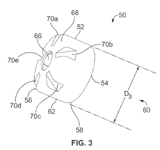
Figure 3 illustrates a first arrangement of a coded ferrule 50. Such ferrule
50 can be
combined with a tubular member (preferably a glass tubular member) and
pierceable
seal to form a cartridge that may be used with a drug delivery device, such as
the pen-
type drug delivery device 10 illustrated in Figure 1. In this arrangement, the
coded
ferrule 50 comprises a molded coded ferrule rather than a metallic ferrule.
Such a
molded ferrule may offer a number of advantages. For example, a molded ferrule
may
enable a more robust and finer coding scheme than it could be applied to a
metal
ferrule. For example, the ferrule 50 may comprise a plastic such as PP,
acetal,
polyamide, or, alternatively, a metal such as zinc or magnesium. In addition,
the
CA 02796742 2012-10-17
WO 2011/131780 PCT/EP2011/056479
19
proposed molded ferrule 50 may be used with standard glass cartridges, such as
the
glass cartridge 20 illustrated in Figures 2A and 2B. Because this standard
cartridge 20
needs not to be modified, the molded ferrule of the present disclosure may
also reduce
cost and technical risk. For example, other ferrule coding arrangements
described
herein may necessitate modification to the glass, which could need development
and
investment in new cartridge manufacturing production equipment and development
of
new manufacturing processes.
The ferrule 50 shown in Figure 3 comprises a cylindrically shaped main body 52
defining a centrally located bore 54. This bore 54 is geometrically configured
for
receiving a distal end of a standard glass cartridge, such as the distal end
of the
cartridge 20 illustrated in Figure 2B. This bore 54 extends from a proximal
end 58 to a
distal end 56 of the main body 52 and, when a cartridge such as the cartridge
20
illustrated in Figure 2 is assembled, the bore 54 is positioned over the
opening defined
by the neck 26 of the cartridge 20. Preferably, the main body 52 has a
diameter D3 60
that is slightly larger than the diameter of the neck 26 of the cartridge
illustrated as D2B.
This main body 52 is also dimensioned to fit within an inner cavity of a
cartridge holder,
such as the inner cavity 11 of the cartridge holderl 4 illustrated in Figure
1. The ferrule
50 further comprises a axially extending wall 62 that extends from the
proximal end 58
of the main body 52 towards the distal end 56 of the main body 52.
Near its distal end 56, the ferrule 50 is provided with a pass through 66. In
one
arrangement, this pass through 66 is sized or configured so that, when the
ferrule 50 is
positioned over the neck 26 of the cartridge 20, the pass through 66 will
expose a
portion of a pierceable seal 33 so as to provide a needle assembly access to
at least a
portion of this seal 33.
Preferably, the molded ferrule 50 comprises coding features and these coding
features
could be applied in various positions and/or locations on the ferrule. As just
one
example, in Figures 3 and 4, this molded ferrule 50 comprises a coding feature
in the
form of a plurality of indentations 70 a-e provided along an end face 68 of
the main body
52. These indentations 70 a-e are arranged so that they will cooperate with a
cartridge
CA 02796742 2012-10-17
WO 2011/131780 PCT/EP2011/056479
holder that includes a cooperating coding mechanism. Although only five
indentations
are illustrated in this preferred arrangement, those of skill in the art will
recognize
alternative indentation arrangements may also be provided, and they may not be
equally sized or equally spaced around the circumference.
5
The ferrule 50 is intended for use with a cartridge holder similar to the
cartridge holder
14 of Figure 1 but a preferred cartridge holder for use with the ferrule 50
would have a
slightly modified inner cavity. For example, Figure 4 illustrates a cross-
sectional view of
a distal end 82 of a modified cartridge holder 80 that could be used with the
ferrule 50.
10 The proximal end (not shown) of the cartridge holder 80 would include a
similar
releasable connection mechanism (e.g., thread, snap lock, snap fit, bayonet
lock, etc.)
as the proximal end 15 of the cartridge holder 14 illustrated in Figure 1.
In this modified cartridge holder 80, the distal end 18 of the cartridge
holder 80
15 comprises a distal threaded section 84 on an outer surface 92 of the holder
80. In
addition, the inner cavity 86 of the holder 80 is configured to comprise an
inner stop
face 88 that has a cooperating coding scheme in the form of a plurality of
raised
features or protrusions 90 a-b. These raised features 90 a-b are geometrically
configured so as to align with or to cooperate with the plurality of recesses
70 a-e
20 provided on the end face 68 of the ferrule 50. For example, Figure 4
illustrates the
molded ferrule 50 illustrated in Figure 3 mounted on a glass cartridge 76,
such as the
cartridge illustrated in Figure 2B. This cartridge 76 and ferrule combination
50 is
illustrated as being partially inserted into the cartridge holder 80 wherein
two raised
features or protrusions 90 a-b are illustrated. These features 90 a-b are
configured so
as to engage two recesses or indentations 70 a-b on the end face 68 of the
ferrule 50.
In this manner, when the cartridge 76 carrying the ferrule 50 is inserted into
the
cartridge holder 80, the indentations 70 a-b of ferrule 50 may cooperate with
the distal
end projections 90a-b such that the ferrule 50 and, therefore, the cartridge
76 can
reside in a final seated position. In this final seated position, the end face
68 of the
ferrule 50 fully abuts the inner stop face 88 of the cartridge holder 80.
CA 02796742 2012-10-17
WO 2011/131780 PCT/EP2011/056479
21
The distal end 82 of the cartridge holder 80 is intended for use with a
standard double
ended needle wherein this needle assembly comprises a hub having an internal
thread.
As such, an outer surface 92 of the cartridge holder 80 is provided with the
outer thread
84 that receives such a hub of the double ended needle. Such an outer thread
84 could
comprise a single or a double start outer thread. In addition, when such
double ended
needle is mounted onto the cartridge holder distal end, the piercing proximal
needle
projects through the pass through 66 and into a pierceable seal of the
cartridge 76. As
such, when the cartridge 76 comprising the ferrule 50 is fully inserted into
the cartridge
holder 80 and the double ended needle assembly is mounted on the distal end 82
of the
cartridge holder 80, the piercing needle pierces the membrane so as to be in
fluid
communication with a medicament 94 contained in the cartridge 76.
One advantage of utilizing a plurality of indentations 70 a-e along an end
face of the
ferrule 50 in combination with the raised features 90 a-e is that such a
coding scheme
may pevent a standard cartridge assembly (such as that illustrated in Figure
2A) from
being used with the cartridge holder 80 illustrated in Figure 4. For example,
if a user
tried to insert the cartridge 20 of Figure 2A into the cartridge holder 80 of
Figure 4, the
protrusions 90 a-b would prevent the cartridge 20 from residing in a final
seated
position. Consequently, since the end face of the ferrule 24 of the cartridge
20 would not
fully abut the inner stop face 88 of the cartridge holder 80, fluid
communication between
an attached needle assembly and the medicament 25 contained within the
cartridge 20
would be prevented. In addition, with an incorrect cartridge, the proximal end
of the
incorrect cartridge would protrude too far out of the holder 80, thereby
preventing
assembly of the cartridge holder 80 to the dose setting member 12 of the
device 10.
Another advantage of the described indentation/protrusion coding scheme is
that it may
prevent rotation of the cartridge76 when the double ended needle is mounted
onto the
distal end of the cartridge holder 80 which may occur by threading the needle
assembly
onto the receiving thread 84 at the distal end of the cartridge holder 80. In
addition, it
may also prevent rotation of the coding relative to cartridge 76. While
inserting the
cartridge 76 into the holder 80, the user is required to hold the cartridge 76
in order to
CA 02796742 2012-10-17
WO 2011/131780 PCT/EP2011/056479
22
align the coding features. Therefore, if the coding features were allowed to
rotate
relative to cartridge 76, it would be difficult to align these coding
features.
Figure 5 illustrates a second arrangement of a coded ferrule 150 for use with
a cartridge
that may be used with a pen-type drug delivery device, such as the drug
delivery device
illustrated in Figure 1. Similar to the ferrule 50 illustrated in Figures 3
and 4, this
ferrule configuration 150 comprises a cylindrically shaped main body 152
defining a
centrally located bore 154. This bore 154 is geometrically configured for
receiving a
distal end of a standard cartridge 176 containing a medicament 178, such as
the distal
10 end of the cartridge 20 illustrated in Figure 2B. This bore 154 extends
from a proximal
end 158 to a distal end 156 of the main body 152. When the cartridge is
inserted, the
aperture is positioned over the opening defined by the neck of the cartridge
176.
Preferably, this main body 152 has a diameter D5 160 that is slightly larger
than the
diameter of the neck of the cartridge, such as D2B 38 as illustrated in Figure
2B. As
illustrated in Figure 6, the main body 152 is dimensioned to fit within an
inner cavity 182
of a cartridge holder 180, such as the holder illustrated in Figure 1. The
ferrule 150
further comprises an essentially smooth axially extending wall 162. Wall 162
extends
from the proximal end of the main body 152 towards the distal end 156 of the
main body
152. Near its distal end 156, the ferrule 150 is provided with a pass through
166.
Ferrule 150 further comprises a coding feature in the form of a plurality of
protrusions
170 a-e provided along an end face 168 of the main body 152. These protrusions
170 a-
e are arranged so that they will cooperate with a cartridge holder 180 that
includes a
cooperating coding mechanism. For example, ferrule 150 is intended for use
with a
cartridge holder 180 similar to the cartridge holder 14 of Figure 1 but with a
modified
inner cavity 182. Figure 6 illustrates the ferrule 150 illustrated in Figure 5
mounted on a
cartridge 176 and partially inserted into such a modified cartridge holder
180.
As can be seen from Figure 6, the cartridge holder 180 comprises a plurality
of
recessed features 184 a-b located within the cartridge holder inner cavity 182
and
located near the distal end 183 of the holder stop face 186. In this manner,
when the
cartridge 176 carrying the ferrule 150 is inserted into the cartridge holder
180, the
projections of ferrule 150 cooperate with the distal end recessed features 184
a-b. The
CA 02796742 2012-10-17
WO 2011/131780 PCT/EP2011/056479
23
ferrule 150 and, therefore, the cartridge 176 can reside in a final seated
position where
the ferrule end face 168 fully abuts the inner stop face 186 of the cartridge
holder 180.
Alternatively, coding features could be provided along a sidewall of a
ferrule. For
example, Figure 7 illustrates another arrangement of a coded ferrule 250 for
use with a
cartridge that may be used with a pen-type drug delivery device, such as the
drug
delivery device 10 illustrated in Figure 1.
In this alternative arrangement, similar to the ferrule arrangements 50 and
150, ferrule
250 comprises a main body 252 defining a centrally located bore 254 configured
for
receiving a distal end of a standard cartridge. This bore 254 extends from a
proximal
end 258 to a distal end 256 of the main body 252 and, when a cartridge such as
the
cartridge 20 illustrated in Figure 2 is assembled utilizing ferrule 250, the
aperture is
positioned over the opening defined by the neck 26 of the cartridge 20.
Preferably, this
ferrule main body 252 has a geometrical configuration that is dimensioned to
fit within
an inner cavity of a cartridge holder. Near its distal end 256, the ferrule
250 is provided
with a pass through 266 on its end face 267.
Molded ferrule 250 no longer comprises a smooth side wall but now comprises a
coding
feature in the form of a side wall 264 having a plurality of axial protrusions
and/or
indentations 268. Alternatively, the ferrule 250 could be coded by its cross-
sectional
shape in a transverse plane. These surfaces may be arranged so that they
cooperate
with a cartridge holder that includes a cooperating coding mechanism. In such
a
cooperating configuration, the cartridge holder would comprise a plurality of
cooperating
features located within an inner cavity and located near the distal end of the
holder. In
this manner, when the cartridge 220 carrying the ferrule 250 is inserted into
the
cartridge holder, the projections of ferrule 250 cooperate with the distal end
recessed
features such that the ferrule 250, and, therefore, cartridge assembly 220,
can reside in
a final seated position with the end face 267 fully abutting the cartridge
holder inner stop
face.
Alternatively, the coding features may be provided along a flange or shoulder
of the
ferrule, e.g. the shoulder at the proximal end of the ferrule. For example,
Figure 8A
CA 02796742 2012-10-17
WO 2011/131780 PCT/EP2011/056479
24
illustrates an alternative ferrule arrangement 300 where the coding
configurations are
provided on a flange 342 of the ferrule 300. Figure 8B provides cross-
sectional
illustration of this ferrule arrangement 300. As illustrated, in this
arrangement, the ferrule
300 comprises a main body 302 defining a centrally located bore 304. Bore 304
is
geometrically configured for receiving a distal end of a cartridge 340. This
bore 304
extends from a proximal end 308 to a distal end 306 of the main body 302 and,
when a
cartridge such as the cartridge illustrated in Figure 2 is assembled utilizing
ferrule 350,
the aperture is positioned over the opening defined by the neck of the
cartridge.
Preferably, this ferrule main body 302 has a geometrical configuration
dimensioned to fit
within an inner cavity of a cartridge holder. Near its distal end 306, the
coded ferrule 300
is provided with a pass through 310.
In one arrangement, the cartridge 340 formed with ferrule 300 is provided with
a locking
ring 320. This locking ring 320 may be added to the ferrule 300 after the
ferrule 300 has
been fitted to the cartridge 340. The locking ring 320 may be rectangular in
its cross-
section and have certain form fit or snap fit features that allow it to be
retained on the
ferrule 300. One of the advantages of such a locking ring arrangement 320 is
that it may
be used to increase the rigidity of the ferrule 300 and to increase its
retention strength.
As illustrated, this locking ring 320 may be provided near the proximal end of
the ferrule
300. In addition, the proximal end of the ferrule 300 may be provided with a
plurality of
slits or cuts 312 a-e so as to increase the flexibility of the ferrule 300,
thereby making it
easier to fit the ferrule 300 over the cartridge neck.
In addition, the ferrule 300 may be provided with a threaded distal end 330.
For
example, in contrast to the cartridge holder 80 illustrated in Figure 4 which
provides one
such threaded section, the ferrule 300 may be provided with a threaded portion
330
along its distal end 306. In this manner, where the ferrule 300 is used with a
cartridge
holder, a distal end of the cartridge holder will be provided with a pass
through so as to
allow the threaded section 330 of the ferrule 300 to be accessible to the user
so that the
user can mount a conventional double ended needle assembly.
CA 02796742 2012-10-17
WO 2011/131780 PCT/EP2011/056479
In addition, in alternative ferrule arrangements, a chamfer or a
ramped/helical surface
may be provided on the ferrule, such as along an outer surface 314 of the main
body
302 of ferrule 300. One advantage of such a configuration is that it would
help a user to
align the coding features on the ferrule 300 with the coding features provided
in or on
5 the cartridge holder and/or drug delivery device. As just one example, the
ferrule 300
may comprise one or more radially outward directed pins. Such pins may have an
extent larger than the outer diameter of the cartridge so as to contact a
sloped surface
along an inner surface of a corresponding cartridge holder. While the
cartridge with
such a ferrule travels axially into the holder during cartridge loading, the
contact
10 between the ferrule and cartridge holder causes the cartridge to rotate,
aligning the
coding features of the ferrule with the cooperating features provided on the
holder.
In the molded ferrule arrangements discussed above, the ferrule may comprise
inwardly
projecting members located within an inner space of the main body bore. In
this
15 manner, the ferrule could be attached to the glass cartridge using these
inwardly
projecting members so that the inwardly projecting members grip behind the
cartridge
neck. Alternative attachment methods may also be used.
Figure 9 illustrates a yet another arrangement of a coded ferrule 350 for use
with a
20 cartridge 380 that may be used with a drug delivery device, such as the
drug delivery
device 10 illustrated in Figure 1. Figure 10 illustrates the ferrule 350
illustrated in Figure
9 mounted on the cartridge 380 and Figure 11 illustrates the ferrule 350
mounted on a
cartridge and partially inserted into a cartridge holder 390.
25 In this arrangement, the coding arrangement is used with cartridge 380
comprising a
ferrule 350, a pierceable membrane 360, and a tubular member having a modified
neck
portion 382. In this arrangement, the ferrule 350 may be metallic or may
comprise a
mouldable or similar other material as previously described.
The ferrule 350 has a similar construction to ferrule 50 illustrated in Figure
3. That is,
ferrule 350 comprises a cylindrically shaped main body 352 defining a
centrally located
bore 354 that extends from a proximal end 358 to a distal end 356 of the main
body
CA 02796742 2012-10-17
WO 2011/131780 PCT/EP2011/056479
26
352. When a cartridge assembly is assembled with such a coded ferrule, the
aperture is
positioned over the opening defined by the neck of the cartridge. The ferrule
350 further
comprises an axially extending wall 362 that extends from the proximal end of
the main
body 352 towards the distal end 356 of the main body 352. Near its distal end
356, the
ferrule 350 is provided with a pass through 366.
One difference between the cartridge 20 that can be used with the ferrule 50
(Figure 2B
and 3) and cartridge 380 for use with the ferrule 350 is that the distal neck
portion 382
of the cartridge 380 has been modified. Preferably, in the arrangement of
Figure 9, the
distal end 382 of the cartridge 380 is modified to comprise a smaller flange
diameter at
the distal end 382 of the cartridge 380. By reducing this cartridge flange
diameter, this
also reduces the overall outer diameter of the ferrule 350. Figure 9
illustrates the ferrule
350 with a reduced diameter D9 378. Moreover, in the example shown, the
diameter of
the pierceable septum has also been reduced so as to accommodate indentations
in the
ferrule, but it may have indentations to match those of the ferrule.
Alternatively, its outer
diameter may be larger than that of the flange 381. In such a configuration,
it would be
deformed by the coding indentations, and may be more securely retained.
As illustrated in Figure 10, reducing the cartridge flange diameter enables
coding
features in the form of indentations 368 a-e to be formed near an end face 364
of the
ferrule 350. This can be accomplished while maintaining the same diameter for
crimping
a metallic ferrule or molding such a molded ferrule on the cartridge 380.
By removing a certain amount of cartridge material (e.g., glass, plastic or
the like) from
the neck portion 382 of the cartridge 380, a user will be prevented from
trying to load a
larger standard cartridge (such as cartridge 20 in Figure 2B) into a modified
cartridge
holder that has been mechanically coded for the smaller diameter of ferrule
350 since
the cartridge holder will now have an inner cavity with a smaller inner
diameter.
Consequently, inadvertent cross use of cartridge assemblies can be reduced.
The ferrule 350 is intended for use with a cartridge holder similar to the
cartridge holder
14 of Figure 1 but with a slightly modified inner cavity. For example, Figure
11 illustrates
a cross-sectional view of a distal end 392 of a modified cartridge holder 390
that could
CA 02796742 2012-10-17
WO 2011/131780 PCT/EP2011/056479
27
be used with the ferrule 350. The proximal end (not shown) of the cartridge
holder 390
would include a similar releasable connection mechanism (e.g., thread, snap
lock, snap
fit, bayonet lock, etc.).
In this modified cartridge holder 390, the distal end 392 comprises a distal
threaded
section 394 on an outer surface 396 of the holder. In addition, the inner
cavity 398 of the
holder 390 is configured to comprise an inner stop face 386 that has a
cooperating
coding scheme in the form of a plurality of raised features or protrusions 388
a-b. These
raised features 388 a-b are geometrically configured so as to align with or
cooperate
with the plurality of recesses 368 a-e provided on the end face of the ferrule
350. In
Figure 11, this cartridge and ferrule combination is illustrated as being
partially inserted
into the cartridge holder 390 wherein two raised features or protrusions 388 a-
b are
illustrated and these features 388 a-b are configured so as to engage two
recesses 368
a-b on the ferrule 350.
Figure 12 illustrates a yet another arrangement of a coded ferrule 400 for use
with a
cartridge that may be used with a pen-type drug delivery device, such as the
drug
delivery device 10 illustrated in Figure 1. Figure 13 illustrates the coded
ferrule 400 of
Figure 12 mounted on a coded cartridge 416 and having a coded pierceable
membrane
430 between the coded ferrule 400 and the coded cartridge 416.
The ferrule 400 is similar in construction to the coded ferrule illustrated in
Figure 9. As
shown in Figure 12, coded ferrule 400 comprises a cylindrically shaped main
body 402
defining a centrally located bore 404. This bore 404 is geometrically
configured for
receiving a distal end of a standard glass cartridge, such as the distal end
of the
cartridge 20 illustrated in Figure 2B. This bore 404 extends from a proximal
end 408 to a
distal end 410 of the main body 402. When a cartridge such as the cartridge
illustrated
in Figure 2 is assembled with this ferrule 400, the aperture is positioned
over the
opening defined by the neck of the cartridge. This main body 402 is also
dimensioned to
fit within an inner cavity of cartridge holder, such as the inner cavity 401
of the cartridge
holder 440 illustrated in Figure 14. The ferrule 400 further comprises an
axially
extending wall 412 that extends from the proximal end of the main body 408
towards
CA 02796742 2012-10-17
WO 2011/131780 PCT/EP2011/056479
28
the distal end 410 of the main body 402. Near its distal end 410, the ferrule
400 is
provided with a pass through 406.
Importantly, the coded ferrule 400 is configured to cooperate with the coded
pierceable
membrane 430 and the coded cartridge 416. For example, in one arrangement, the
coded ferrule 400 comprises a plurality of indentations 420 a-e. Similarly,
the pierceable
membrane 430 may comprise a similar number of indentations 431 a-e. As
previously
described with respect to Figure 9, the pierceable septum 430 may have the
same
number of indentations so as to match those of the ferrule 400. Alternatively,
the
piercable septum 430 may have the same number of indentations as the coded
neck
418 of the cartridge 416 but yet fewer indentations than the ferrule 400. In
this later
configuration, the same cartridge 416 and membrane 430 could be used with a
plurality
of different coded ferrules 400.
The coded neck 418 of the cartridge 416 also comprises a plurality of
indentations 417
a-e. As such, when the ferrule 400 is crimpled/molded/fitted over the
cartridge 416 to
contain the coded membrane 430, these various indentations 417 a-e align with
one
another so as to form a cartridge assembly as illustrated in Figure 13. One
advantage of
this coding arrangement is that since this coding feature comprises a
plurality of axial
grooves provided on the side of the cartridge flange, this configuration
removes the
need to reduce or alter the flange diameter of the cartridge 416 and septum
430. One
advantage of such a coding scheme is that the indentations on cartridge 416
could be
standard for a wide range of drugs, but the ferrule 400 may only have some of
the
indentations, so that the ferrule 400 (and not the cartridge 416 or member)
would be
coded to a specific drug.
Another advantage of such a coding arrangement is that it allows for longer
coding
indentations to be used in the cartridge holder 416. For example, Figure 14
illustrates
the assembly 432 illustrated in Figure 13 partially inserted into a cartridge
holder 440.
The distal end 442 of the holder 440 comprises a stop face. Figure 14
illustrates the
cartridge assembly 432 partially inserted into the cartridge holder 440
wherein two
raised features or protrusions 444 a-b are illustrated and these features 444
a-b are
CA 02796742 2012-10-17
WO 2011/131780 PCT/EP2011/056479
29
configured so as to cooperate with two recesses or indentations 420 a-b on the
end
face 414 of the ferrule 400. When the cartridge assembly 432 carrying the
ferrule 400 is
inserted into the cartridge holder 440, the indentations 420 a-b cooperate
with the distal
end projections 444 a-b such that the cartridge 432 can reside in a final
seated position
with the ferrule end face 414 fully abutting the inner stop face 416 of the
cartridge holder
440.
Increasing the length of such coding protrusions 444 a-b increases a potential
`stand-off'
distance if an incorrect cartridge is inserted into the cartridge holder 440.
That is, the
stand-off distance being the distance between the cartridge and the final
seated position
where the end face of the ferrule 400 abuts the end stop of the cartridge
holder inner
cavity.
In the arrangement illustrated in Figures 12-14, the ferrule 400 may be metal
or a
molded polymer. Alternatively, the ferrule may comprise a heat-shrink
material. Such a
heat shrink material could reduce tolerances thus allowing the ferrule 400 to
grip the
distal bead of the cartridge 416 more closely. Moreover, where the ferrule 400
comprises a malleable or a metallic material, the ferrule 400 could be
manufactured
first, the cartridge 416 could be fabricated, and then the coding could be
pressed into
the ferrule end face after it has been fitted onto the cartridge 416.
Alternatively, the
coding features could be formed by heat causing material to flow into any
coding
grooves on the cartridge 416.
Figure 15 illustrates a yet another arrangement of a coded ferrule 500 for use
with a
cartridge that may be used with a pen-type drug delivery device, such as the
drug
delivery device 10 illustrated in Figure 1. Figure 16 illustrates the coded
ferrule 500 of
Figure 15 mounted on a cartridge 516 and having a coded support ring 530
between the
cartridge 516 and the coded ferrule 500.
The ferrule 500 is similar in construction to the previously described coded
ferrules. For
example, as shown in Figure 15, coded ferrule 500 comprises a cylindrically
shaped
main body 502 defining a centrally located bore 504. This bore 504 is
geometrically
CA 02796742 2012-10-17
WO 2011/131780 PCT/EP2011/056479
configured for receiving a distal end of a cartridge, such as the distal end
of the
cartridge 20 illustrated in Figure 2B. This bore 504 extends from a proximal
end 508 to a
distal end 510 of the main body 502. When a cartridge such as the cartridge
illustrated
in Figure 2 is assembled, the aperture is positioned over the opening defined
by the
5 neck of the cartridge. This main body 502 is dimensioned to fit within an
inner cavity of a
cartridge holder. The ferrule 500 further comprises an axially extending wall
512 that
extends from the proximal end of the main body 502 towards the distal end 510
of the
main body 502. Near its distal end 510, the ferrule 500 is provided with a
pass through
506.
Importantly, the coded ferrule 500 is configured to cooperate with a coded
support ring
530 and the pierceable membrane 526. For example, in one arrangement, the
coded
ferrule 500 comprises a plurality of indentations 531 a-e. Similarly, the
coded support
ring 530 comprises a plurality of indentations 522 a-e. As such, when the
ferrule 500 is
crimped/molded/fitted over the cartridge 516 to contain the coded support ring
530 and
the membrane 526, the indentations of the coded ferrule 500 and the support
ring 530
align with one another so as to form a cartridge assembly 540 as illustrated
in Figure
16.
Figure 17 illustrates a partial perspective view of the coded ferrule 500 and
the support
ring interface. As shown, the inner indentations 531 a-c of the coded ferrule
500
cooperate with the recesses 522 a-c provided along the external circumference
of the
support ring 530. This support ring 530 further defines an inner bore 527 and
the
pierceable membrane 526 is retained in the recess in part by the ferrule 500
being
crimped over a bead 524 of the cartridge 516.
One advantage of such a coded support ring arrangement is that, since the
coding
features are provided in the form of a plurality of axial grooves provided on
the support
ring 530, there is no longer a need to reduce the flange diameter of the
cartridge 516.
Consequently, standard type cartridges may be used with this coding
arrangement.
Another advantage of this coding configuration is that the addition of the
coded support
ring 530 increases the robustness of the coded ferrule 500.
CA 02796742 2012-10-17
WO 2011/131780 PCT/EP2011/056479
31
In addition, the ferrule coding features may be formed on the ferrule 500
before the
ferrule 500 is crimped or fitted over the cartridge neck. Alternatively, the
coding features
may be formed after the cartridge assembly is assembled. Although the glass
cartridge
is shown as having a standard neck, the support ring 530 could also sit on a
shoulder
formed in the cartridge (as illustrated in Figure 9).
Figure 18 illustrates another arrangement of a coded ferrule 550 for use with
a cartridge
that may be used with a pen-type drug delivery device, such as the drug
delivery device
10 illustrated in Figure 1.
Similar to the previously described ferrules, this ferrule configuration 550
comprises a
cylindrically shaped main body 551 defining a centrally located bore 554. This
bore 554
is configured for receiving a distal end of a cartridge 576 and extends from a
proximal
end 558 to a distal end 556. When a cartridge is inserted, the aperture is
positioned
over the opening defined by the neck of the cartridge 576. This main body 551
is
dimensioned to fit within an inner cavity of a cartridge holder.
The ferrule 550 further comprises an essentially smooth axially extending wall
562. Wall
562 extends from the proximal end of the main body 551 towards the distal end
556 of
the main body 551. Near its distal end 556, the ferrule 550 is provided with a
pass
through 566. Ferrule 550 further comprises coding features in the form of a
plurality
slots 552 a-e provided in the axially extending wall 562. These coding
features 552 a-e
cooperate with appropriate sized and configured geometrical projections
provided within
the internal cavity of the cartridge holder. One advantage of such an
arrangement is that
no change is required to a standard cartridge and, therefore, there would be
no
additional development and/or investment. There would also be no change to a
standard septum so that additional drug compatibility testing would not be
needed. In
addition, since the outer diameter of the cartridge 576 would remain
unchanged, there
would be no impact on the overall size of the drug delivery device. Moreover,
longer
coding features could be used, thereby making it more obvious to a user if he
or she
attempts to load an incorrect cartridge. In addition, because material has
been removed
CA 02796742 2012-10-17
WO 2011/131780 PCT/EP2011/056479
32
from the ferrule, a small inner cavity of the cartridge holder could be used
and,
therefore, a cartridge having a standard ferrule would not be properly seated
within such
a cartridge holder.
Figure 19 illustrates yet another arrangement of a coded ferrule 600 for use
with a
cartridge that may be used with a pen-type drug delivery device, such as the
drug
delivery device 10 illustrated in Figure 1. Figure 20 illustrates a top
perspective view of
the coded ferrule 600 illustrated in Figure 19. Similar to the previous
ferrule
arrangements, ferrule 600 comprises a main body 652 defining a centrally
located bore
654. Bore 654 is geometrically configured for receiving a distal end of a
standard glass
cartridge. This bore 654 extends from a proximal end 658 to a distal end 656
of the
main body 652. When a cartridge assembly is assembled utilizing ferrule 600,
the
aperture is positioned over the opening defined by the neck of the cartridge.
Near its
distal end 656, the ferrule 600 is provided with a pass through 666.
Preferably, this ferrule main body 652 has a geometrical configuration
dimensioned to fit
within an inner cavity of a cartridge holder. The ferrule main body 652
further comprises
an axially extending wall 662 that extends from the proximal end 658 to the
distal end
656 of the main body 652. This axially extending wall 662 comprises coding
features in
the form of a plurality of thick and thin sections 672 a-f, which may be
pressed into the
ferrule material. These coding features 672 a-f cooperate with appropriate
sized and
configured geometrical recesses provided within the internal cavity of the
cartridge
holder.
Although aimed primarily at the insulin market, the disclosed coded ferrule
may apply to
other drugs. The disclosure may apply to various devices, including the
following
examples:
An injector pen with a cartridge (e.g. 3m1 cylindrical glass cartridge) and a
separate
holder.
CA 02796742 2012-10-17
WO 2011/131780 PCT/EP2011/056479
33
An injector pen with a cartridge (e.g. 3m1 cylindrical glass cartridge) non-
removably
retained in a holder, so that the holder will be disposed of with the primary
pack.
An injector pen where the primary pack attaches directly to the pen, e.g. an
injection-molded polymer cartridge.
Any drug delivery device with any type of primary pack, e.g. inhaler, pouch.
In other situations, the disclosed coding system may apply to any drug
delivery device,
with any type of reservoir or primary pack, e.g. inhaler, pouch. For example,
Figure 21
illustrates a drug reservoir 700 comprising a vessel 704 that contains a
medicament
706. A stopper 708 is provided along a distal end of the vessel 704 and is
attached to
the vessel 704 so as to prevent the medicament 706 from exiting the vessel
704. A
coded ferrule 702 is provided on the vessel 704 near an output port 710 of the
vessel
704. This output port 710 has a rigid neck and a coded ferrule 702 is provided
along this
neck.
The disclosed coding system results in a number of advantages. For example,
the
proposed coded ferrule arrangements assist a user to distinguish between
medicaments, thereby helping to ensure that a drug delivery device can only be
used
with a medicament for which the device is intended. Therefore, with the system
applied
to a cartridge, the cartridge is prevented from being confused with any other
drug by
loading a cartridge with an incorrect or unwanted interface. The disclosed
coded ferrule
prevents a user from completing one or more of the following actions: fully
inserting the
cartridge into an incorrect cartridge holder or attaching the cartridge and/or
the cartridge
holder onto an incorrect dose setting mechanism.
The disclosed coded ferrule also results in a low cost coding mechanism since
the
proposed ferrules do not require a large number of parts and can be
manufactured in a
cost effective manner. Moreover, there are quite a large number of different
ferrule
coding configurations between the ferrule and the cartridge holder that may be
used.
Consequently, with the proposed coded ferrule schemes, a large number of
CA 02796742 2012-10-17
WO 2011/131780 PCT/EP2011/056479
34
medicaments can be distinguished from one another. In addition, with the
presently
disclosed coding schemes, if a user attempts to load an incorrect cartridge
into a
cartridge holder designed for a different cartridge, the user will be alerted
at an early
stage of the assembly process.
In addition, The disclosed system can be used to prevent errors during
manufacturing,
when inserting cartridge into disposable cartridge holders or disposable
devices.
Exemplary embodiments of the present disclosure have been described. However,
as
those of skill in the art will recognize certain changes or modifications to
such
arrangements may be made. As just one example, certain coding elements of one
of
the preferred arrangements discussed herein may be taken from one arrangement
and
combined with certain coding arrangements of other arrangements.
As merely one example, Figure 22 illustrates one such alternative coding
arrangement
800. This coding arrangement 800 represents a combination coding arrangement
of the
coding scheme illustrated in Figure 9 combined with that coding scheme
illustrated in
Figure 15. In such a combined arrangement, the coding scheme would comprise a
coded ferrule 802, a coded permeable member 830, a ring 860, and a cartridge
880.
Such cartridge 880 would comprise a neck 882 having a reduced diameter 881.
As yet another example, Figure 23 illustrates another such alternative
arrangement 900.
This coding arrangement 900 represents an alternative coding arrangement of
the
coding scheme illustrated in Figure 9. In this arrangement, the coding
arrangement is
used with a cartridge 980 comprising a ferrule 950, a pierceable membrane 960,
and a
tubular member having a modified neck portion near the distal end 982 of the
cartridge
980. As before, the ferrule 950 may be metallic or may comprise a mouldable or
similar
other material as previously described. In this arrangement, the cartridge 980
for use
with the ferrule 950 has been modified to comprise a smaller flange diameter
981 at the
distal end 982 of the cartridge 980.
CA 02796742 2012-10-17
WO 2011/131780 PCT/EP2011/056479
The ferrule 950 has a generally similar construction to ferrule 350
illustrated in Figure 9.
That is, ferrule 950 comprises a cylindrically shaped main body 952 defining a
centrally
located bore 966 that extends from a proximal end 958 to a distal end 956 of
the main
body 952. When the cartridge 980 is assembled with such a coded ferrule 950,
the
5 aperture is positioned over the opening defined by the neck of the cartridge
980. The
ferrule 950 further comprises a proximal flange 959 adjacent an axially
extending wall
962. This wall 962 extends from the proximal flange 958 of the main body 952
towards
the distal end 956 of the main body 952. Near its distal end 956, the ferrule
950 is
provided with a beveled edge 968 and a pass through 954.
Those skilled in the art will understand, however, that further changes,
modifications,
revisions and/or additions may be made to the presently disclosed arrangements
without departing from the true scope and spirit of the present disclosure,
which is
defined by the claims.
The scope of the disclosure is defined by the content of the claims. The
disclosure is not
limited to specific embodiments but comprises any combination of elements of
different
embodiments. Moreover, the disclosure comprises any combination of claims and
any
combination of features disclosed by the claims.
CA 02796742 2012-10-17
WO 2011/131780 PCT/EP2011/056479
36
REFERENCE NUMERALS:
9 piston rod
drug delivery device
5 11 cartridge cavity
12 dose setting member
13 distal end
14 cartridge holder
proximal end
10 16 removable cap
17 dose setter
18 distal end
cartridge
15 21 thread
22 tubular barrel
23 annular bead
24 metallic sleeve /ferrule
medicament
20 26 neck
27 opening
28 stopper
29 outer surface or sidewall
distal end
25 31 shoulder
32 proximal end
33 seal or septum
34 diameter D,
36 diameter D2
30 38 diameter D2B
50 ferrule
CA 02796742 2012-10-17
WO 2011/131780 PCT/EP2011/056479
37
52 main body
54 bore
56 distal end of main body
58 proximal end of main body
60 diameter D3
62 wall
66 pass through
68 end face
70 a-e indentation
76 cartridge
80 cartridge holder
82 distal end
84 distal threaded section
86 inner cavity
88 inner stop face
90 a-b raised feature
92 outer surface
94 medicament
104 cartridge holder
150 ferrule
152 main body
154 bore
156 distal end
158 proximal end
160 diameter D5
162 wall
166 pass through
168 end face
CA 02796742 2012-10-17
WO 2011/131780 PCT/EP2011/056479
38
170 a-e protrusion
176 cartridge
178 medicament
180 cartridge holder
182 inner cavity
183 distal end
184 a-b recessed feature
186 holder stop face
220 cartridge
250 ferrule
252 main body
254 bore
256 distal end
258 proximal end
264 side wall
266 pass through
267 end face
268 coding feature
300 ferrule
302 main body
304 bore
306 distal end
308 proximal end
310 pass through
312 a-e cut
314 outer surface
320 locking ring
330 distal end
340 cartridge
342 flange
CA 02796742 2012-10-17
WO 2011/131780 PCT/EP2011/056479
39
350 ferrule
352 main body
354 bore
356 distal end
358 proximal end
360 membrane
362 wall
364 end face
366 pass through
368 a-e indentation/recess
378 diameter D9
380 cartridge
381 flange
382 neck portion
386 stop face
388 a-e features
390 cartridge holder
392 distal end
394 distal threaded section
396 outer surface
398 inner cavity
400 ferrule
401 inner cavity
402 main body
404 bore
406 pass through
408 proximal end
410 distal end
412 wall
414 end face
416 cartridge
CA 02796742 2012-10-17
WO 2011/131780 PCT/EP2011/056479
417 coding feature / indentation
418 neck
420 a-e indentation
430 membrane/septum
5 431 a-e indentation
432 cartridge
440 cartridge holder
442 distal end
444 a-b protrusion
500 ferrule
502 main body
504 bore
506 pass through
508 proximal end
510 distal end
512 wall
516 cartridge
522 a-e indentation
524 bead
526 membrane
527 inner bore
530 support ring
531 a-e indentation
540 cartridge
550 ferrule
551 main body
552 a-e slot
554 bore
556 distal end
558 proximal end
562 wall
CA 02796742 2012-10-17
WO 2011/131780 PCT/EP2011/056479
41
566 pass through
576 distal end of cartridge
600 ferrule
652 main body
654 bore
656 distal end
658 proximal end
662 wall
666 pass through
672 a-f section
700 reservoir
702 ferrule
704 vessel
706 medicament
708 stopper
710 output port
800 coding arrangement
802 ferrule
830 member
860 ring
880 cartridge
881 diameter
882 neck
900 arrangement
950 ferrule
952 main body
954 pass through
CA 02796742 2012-10-17
WO 2011/131780 PCT/EP2011/056479
42
958 proximal end
960 membrane
962 wall
966 bore
968 edge
980 cartridge
981 flange diameter
982 distal end