Note: Descriptions are shown in the official language in which they were submitted.
CA 02796795 2012-11-27
=
(
Docket Number DEX11-111A
Title
Multi-axle Vehicle Suspension System
Field of the Invention
The invention relates to a multi-axle vehicle
suspension system, and more particularly to a multi-axle
vehicle suspension system having at least two torsion
axles, each torsion axle coupled to a vehicle frame, and
further having a pivotal member pivotally coupled to the
vehicle frame and pivotally coupled to each torsion axle.
Background of the Invention
Conventional multi-axle assemblies for trucks or
trailers may comprise two or more axles. In the case of a
two axle arrangement, four leaf springs are typically used.
Two leaf springs are on each side of the frame. The remote
ends of each pair of springs are usually supported within
hanger brackets which are secured to the frame. The
adjacent ends of each pair of springs can be supported by a
pivotally mounted equalizer. The equalizers are in turn
supported by hanger brackets which are secured to the
frame.
When the front wheels in the tandem suspension, for
example, encounter a condition in the road producing a
vertical movement of the front axle, the resultant
deflection in the front springs is transmitted in part by
the equalizer to the rear springs. This results in an
equalizing effect in which any vertical displacement of
either axle is distributed between the springs which
minimizes the weight differential between the axles.
1
CA 02796795 2012-11-27
1
( .
In the instance of a vehicle equipped with a prior art
equalization tandem one problem concerns inadequate and
abrupt load equalization from one axle to another. As one
end of the equalizer rotates upwardly at the point at which
the spring end contacts the leaf spring, the other end
abruptly rotates downward. This action causes abrupt and
unequal moments about the center pivot point of the
equalizer; inequality increases as the range of equalizer
movement increases.
The end results of improper load equalization are
numerous. If the axle which encounters bumps and overloads
is unpowered, a loss of traction can occur on the powered
axle. The suspension components, and springs in particular,
are subjected to higher stresses and therefore their
service life is shortened appreciably. As the leaf springs
are subjected to overload they progressively lose capacity
to absorb energy and therefore transmit more energy through
the mounting brackets to the vehicle frame.
Increased
input of energy into the vehicle frame can often contribute
at given loads, speeds and highway conditions to damage to
the vehicle. Further, wherever an unequal load distribution
occurs within a tandem suspension, the axle which is
overloaded transmits its load to the roadway in a manner
that can be detrimental to the roadway. The
foregoing
arguments also apply to suspensions comprising more than
two axles.
Torsion axles have been known for many years. Torsion
axles have proven to be extremely popular primarily because
if one wheel hits a bump or rut, it can react independently
of the other wheel, which may not have hit a bump or rut at
the exact same time. This torsion axle concept therefore
operates to keep a trailer or the like moving as straight
2
CA 02796795 2012-11-27
as possible behind a towing vehicle and absorbs some of the
shock of the road over which it is passing with an
independent suspension. This can be contrasted with a
straight axle situation where if one wheel were to drop
into a rut or the like and be slowed down for that reason
while the wheel on the other side of the trailer did not
have the same experience at the same time, the trailer
would tend to turn somewhat to allow the wheel that is on
the flat part of the road to move forward while the wheel
that is in the rut would be restrained, therefore causing
the axle to be not perpendicular with the direction of
towing of the vehicle itself, assuming in this example that
the trailer was being towed on a straight portion of the
road.
The two aforementioned torsion axles are typically
constructed of a square axle in cross section with
elongated rubber members all disposed within a larger tube.
One of the most common and popular torsion axles is a
TorFlex0 rubber torsion suspension system by Dexter Axle
Company. This mentioned torsion axle has independent and
separate stub axles on each side to enhance the independent
aspect of such an axle.
Representative of the art is US patent no. 6,340,165
which discloses a vehicle suspension system assembly for
attachment to a vehicle frame having a torsion axle and at
least two ground engaging wheels operatively rotatably
attached to each respective end of the torsion axle has an
attachment member which is adapted to be attached to the
frame. An arm is operably pivotally attached to the
attachment member along an axis. A torsion axle is received
in a torsion axle receiving portion of the assembly at a
first distance spaced from the aforementioned axis for
3
CA 02796795 2012-11-27
selectively receiving the torsion axle. An air bag is
operatively disposed between the frame and the arm, the air
bag being spaced at a second distance from the axis. A
linkage element of variable length, which can be a shock
absorber, is operably attached to the frame and to the arm
whereby the arm will be held at a predetermined position
with respect to the frame and yet allow the arm to pivot
about the axis. In a preferred embodiment, the air bag is
spaced further away from the pivotal axis of the arm than
is the torsion axle.
Further representative of the art is US patent no.
7,753,400 which discloses a multi-axle leaf spring
suspension having a compliant equalizer. The leaf springs
are mounted one behind the other on each side of the
vehicle. Adjacent ends of the leaf springs are pivotally
attached to the compliant equalizer. The compliant
equalizer is pivotally mounted to a vehicle frame. The
compliant equalizer comprises a pair of arms that are
pivotally connected to each other in a scissor-like
fashion. One end of each arm is pivotally connected to the
end of a leaf spring. The other end of each arm is
cooperatively arranged to contain and compress a spring
member between them. The compliant equalizer reduces the
magnitude of shocks that would be otherwise transmitted to
the suspension and frame by absorbing them through
compression of the spring member.
What is needed is a multi-axle vehicle suspension
system having at least two torsion axles, each torsion axle
coupled to a vehicle frame, and further having a pivotal
member pivotally coupled to the vehicle frame and pivotally
coupled to each torsion axle. The present invention meets
this need.
4
CA 02796795 2012-11-27
Summary of the Invention
The primary aspect of the invention is to provide a
multi-axle vehicle suspension system having at least two
torsion axles, each torsion axle coupled to a vehicle
frame, and further having a pivotal member pivotally
coupled to the vehicle frame and pivotally coupled to each
torsion axle.
Other aspects of the invention will be pointed out or
made obvious by the following description of the invention
and the accompanying drawings.
The invention comprises a multi-axle vehicle
suspension system comprising a first torsion axle mounted
to a first suspension pivot member, the first suspension
pivot member pivotally coupled to a vehicle frame, a second
torsion axle mounted to a second suspension pivot member,
the second suspension pivot member pivotally coupled to the
vehicle frame, a pivot member pivotally coupled to the
vehicle frame, the first suspension pivot member pivotally
coupled to the pivot member, and the second suspension
pivot member pivotally coupled to the pivot member.
Brief Description of the Drawings
The accompanying drawings, which are incorporated in
and form a part of the specification, illustrate preferred
embodiments of the present invention, and together with a
description, serve to explain the principles of the
invention.
Figure 1 is a side view of the inventive suspension.
Figure 2 is a lower perspective view of the inventive
suspension system.
Figure 3 is an upper view of the inventive suspension
system.
5
CA 02796795 2012-11-27
Figure 4 is a detail of the torsion axle.
Detailed Description of the Preferred Embodiment
Figure 1 is a side view of the inventive suspension.
The inventive system comprises a multi-axle vehicle
suspension system comprising a first torsion axle mounted
to a first suspension pivot member, the first suspension
pivot member pivotally coupled to a vehicle frame, a second
torsion axle mounted to a second suspension pivot member,
the second suspension pivot member pivotally coupled to the
vehicle frame, a pivot member pivotally coupled to the
vehicle frame between the first suspension pivot member and
the second suspension pivot member, the first suspension
pivot member pivotally coupled to the pivot member, and the
second suspension pivot member pivotally coupled to the
pivot member.
It is understood that Fig. 1 shows one side of a
vehicle suspension, a like arrangement being present on the
other side of the vehicle. The theoretical direction of
travel for the frame is D.
The vehicle comprises a frame F. Mount Fl and mount F2
and mount F3 are affixed to the frame F. A suspension pivot
member 1000 is pivotally coupled to mount Fl.
One end of a suspension pivot member 100 is pivotally
coupled to mount F3. The other end of the suspension pivot
member is pivotally coupled to a coupling member 101.
Coupling member 101 is also pivotally coupled to pivot
member 1000.
One end of a suspension pivot member 200 is pivotally
coupled to mount F2. The other end of the suspension pivot
member is pivotally coupled to a coupling member 201.
6
CA 02796795 2012-11-27
Coupling member 201 is also pivotally coupled to pivot
member 1000.
A torsion axle assembly 300 is installed in suspension
pivot member 100. Torsion axle assembly 300 is described
in Figure 4. A wheel and tire combination W1 is
rotationally mounted to the axle assembly at CL1.
A torsion axle assembly 400 is installed in suspension
pivot member 200. Torsion axle assembly 400 is described
in Figure 4. A
wheel and tire combination W2 is
rotationally mounted to the axle assembly at CL2.
As a vehicle travels on a road the suspension absorbs
movement of axles Al and A2 by movement of each of the
suspension pivot members 100 and 200, as well as by the
pivoting movement of pivot member 1000. Pivot member 1000
pivots on mount Fl to further absorb and transmit
differential movement of the two axle assemblies 300, 400.
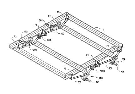
Figure 2 is a lower perspective view of the inventive
suspension system. Two torsion axles 300, 400 are shown
mounted to suspension pivot members 100, 200, respectively.
Axle 300 comprises a spindle 301 and spindle 302 on
opposite sides of the axle. Axle 400 comprises a spindle
401 and spindle 402 on opposite sides of the axle. Wheel
W1 is attached to spindle 301. Wheel
W2 is attached to
spindle 401. A wheel is also attached to each spindle 302
and spindle 402.
Figure 3 is an upper view of the inventive suspension
system. The system enjoys multiple pivot points that are
available to absorb movement of the suspension system as
the vehicle rolls over a road surface. Suspension pivot
member 100 pivots about pivot points P1 and P2. Suspension
pivot member 200 pivots about pivot points P7 and P5.
Pivot member 1000 pivots about pivot point P4.
Coupling
7
CA 02796795 2012-11-27
member 101 pivots about pivot points P2 and P3. Coupling
member 201 pivots about pivot points P5 and P6. Torsional
axle assembly 300 pivots about pivot point P8.
Torsion
axle assembly 400 pivots about pivot point P9.
The geometry of the system can be adjusted by
selecting the desired location of each pivot point P8 and
P9 along the length of each suspension pivot member 100 and
pivot member 200 respectively. Pivot
point P8 may be
located to one side or the other of the suspension pivot
member 100 along its length as shown in Figure 1, or it may
be centered in suspension pivot member 100 as well. Pivot
point P9 may be located to one side or the other of the
suspension pivot member 200 along its length as shown in
Figure 1, or it may be centered in suspension pivot member
200 as well. Further,
pivot points P8 and P9 need not be
located in the same relative position on each respective
suspension pivot member. In the preferred embodiment each
spindle 301 and spindle 401 is approximately centered
between each pivot point P1, P2 and P5, P7 respectively.
Each wheel and tire W1 and wheel and tire W2 and the
internals of each torsion axle assembly will damp
oscillations generated in the system by movement of the
vehicle over a road surface and will distribute the vehicle
load over the road surface more evenly than a conventional
suspension.
Figure 4 is a detail of the torsion axle. The torsion
axle comprises a plurality of rubber cords disposed within
an axle member, and a torsion member situated within the
axle member by the rubber cords, and finally, the torsion
member connected to a spindle for mounting a vehicle tire.
Each torsion axle 300 and axle 400 comprises the
arrangement described herein for each vehicle tire.
8
CA 02796795 2014-07-21
32025-1
More particularly, spindle 301 is attached to torsion
arm 303. Torsion member 304 is attached to torsion arm 303.
Torsion member 304 is rectangular or square in cross-
section.
Torsion member 304 is disposed within an axle
member 306 receiving portion 307. Axle
member 306 has a
rectangular or square cross-section. Also disposed within
axle member 306 is a plurality of rubber cords 305. Rubber
cords 305 are of a sufficient size and are disposed between
the torsion member 304 and axle member 306 in a manner
which counters rotational movement of torsion member 304
when a load is applied to the spindle 301. In the
preferred embodiment there are four rubber cords 305.
Since the rubber cords are elastic and somewhat
compressible, this characteristic allows rotational
movement of torsion member 304 which is roughly
proportionate to the magnitude of the load applied to the
axle spindles. The
rotation of each torsion member is
typically less than 45 .
Although forms of the invention have been described
herein, it will be obvious to those skilled in the art that
variations may be made in the construction and relation of
parts without departing from the scope of the
invention described herein.
9