Note: Descriptions are shown in the official language in which they were submitted.
CA 2796830 2017-03-23
1
GASOLINE ENGINE EMISSIONS TREATMENT SYSTEMS HAVING PARTICULATE
FILTERS
[0001] Deleted.
TECHNICAL FIELD
[0002] This invention pertains generally to emission treatment systems
having catalysts used
to treat gaseous streams of gasoline engines containing hydrocarbons, carbon
monoxide, and oxides
of nitrogen in conjunction with particulates. More specifically, this
invention is directed to three-
way conversion (TWC) catalysts or oxidation catalysts, coated onto and within
particulate filters,
such as soot filters.
BACKGROUND
[0003] Particulate emissions for gasoline engines are being subject to
regulations, including
the upcoming Euro 6 (2014) standards. In particular, certain gasoline direct
injection (GDI) engines
have been developed whose operating regimes result in the formation of fine
particulates. Existing
aftertreatment systems for gasoline engines are not suitable for achieving the
proposed particulate
matter standard. In contrast to particulates generated by diesel lean burning
engines, the particulates
generated by gasoline engines, such as GDI engines, tend to be finer and in
lesser quantities. This
is due to the different combustion conditions of a diesel engine as compared
to a gasoline engine.
For example, gasoline engines run at a higher temperature than diesel engines.
Also, hydrocarbon
components are different in the emissions of gasoline engines as compared to
diesel engines.
[0004] Emission standards for unburned hydrocarbons, carbon monoxide and
nitrogen oxide
contaminants continue to become more stringent. In order to meet such
standards, catalytic
converters containing a three-way conversion (TWC) catalyst are located in the
exhaust gas line of
internal combustion engines. Such catalysts promote the oxidation by oxygen in
the exhaust gas
stream of unburned hydrocarbons and carbon monoxide as well as the reduction
of nitrogen oxides
to nitrogen.
CA 02796830 2012-10-18
WO 2011/133503
PCT/US2011/032978
2
[0005] A catalyzed particulate trap comprising a TWC catalyst coated onto
or within
a particulate trap is provided in U.S, Patent Application Pub. No.
2009/0193796 (Wei). The
TWC catalyst can be coated on an inlet side, an outlet side, or both of the
filter.
100061 Backpressure and volume constraints exhaust systems can limit the
ability to
add additional treatment components. In some GDI emissions systems, two or
more TWC
catalyst composites in combination with NOx traps and SCR catalysts are needed
to achieve
emissions standards. It is a challenge for such systems to accommodate any
additional
bricks or canisters along the exhaust pipe.
100071 As particulate standards become more stringent, however, there is a
need to
provide particulate trapping functionality without unduly crowding the exhaust
pipe and
increasing backpressure. Moreover, HC, NOx, and CO conversions continue to be
of
interest. Certain filter technology has relatively small pores and/or smaller
porosity
intended to capture fine particulate matter, but such filters generally cannot
accommodate
sufficient catalyst loading to meet HC, NOx, and CO conversion requirements,
[0008] There is a continuing need to provide a catalyzed filter that
provides
sufficient TWC in conjunction with an efficient filter without unduly
increasing
backpressure so that regulated HC, NOx, and CO conversions can be achieved
while
meeting particulate matter emissions.
SUMMARY
[0009] Provided are exhaust systems and components suitable for use in
conjunction
with gasoline engines to capture particulates in addition to treating gaseous
emissions such
as hydrocarbons, nitrogen oxides, and carbon monoxides. Of interest is
providing a
particulate filter for gasoline engines (GPFs or PFGs) that provides full
three-way
conversion (TWC) functionality with minimal impact on backpressure. It is
recognized that
a TWC catalyzed filter may need to be used in conjunction with a second TWC
catalyst in
order to meet regulations and car manufacturer requirements. Particulate
matter from
gasoline engines are primarily generated during cold start. This is in
contrast to the way
particulate matter is generated from diesel engines, which is throughout
operation of the
engine at a roughly constant rate.
[0010] Aspects include exhaust treatment systems comprising a three-way
conversion (TWC) catalyst coated onto and/or within a particulate filter in an
emission
treatment system downstream of a gasoline direct injection engine for
treatment of an
CA 2796830 2017-03-23
3
exhaust stream comprising hydrocarbons, carbon monoxide, nitrogen oxides, and
particulates.
[0010a] In
accordance to a particular embodiment, there is provided an emission treatment
system downstream of a gasoline direct injection engine for treatment of an
exhaust stream
comprising hydrocarbons, carbon monoxide, nitrogen oxides, and particulates,
the emission
treatment system comprising a catalyzed particulate filter comprising:
a three-way conversion (TWC) catalytic material that is coated onto or within
a
particulate filter having an uncoated porosity;
wherein the catalyzed particulate filter has a coated porosity that is
substantially the
same as the uncoated porosity of the particulate filter.
[0011] A
first aspect provides a catalyzed particulate filter whose coated porosity is
substantially the same as its uncoated porosity. That is, such a coated filter
results in a backpressure
or pressure drop that is non-detrimental to the performance of the engine. A
non-detrimental
pressure drop means that the engine will perform generally the same (e.g.,
fuel consumption) in a
wide range of engine operational modes in the presence of a filter substrate
that is either in a coated
or an uncoated state. One or more detailed embodiments provide that the
uncoated porosity and the
coated porosity are within 7% (or 6%, or 5%, or 4%, or 3%, or 2.5%, or 2%, or
even 1%) of each
other. Porosity of the filter, coated or uncoated, is measured on the filter.
One way to measure
porosity is to section the filter, measure the porosity of each section, and
average the results. For
example, a filter can be sectioned into a front/inlet piece and a rear/outlet
piece, the porosity of
each piece can be taken, and the results can be averaged.
[0012]
Another aspect provides a catalyzed particulate filter comprising a three-way
conversion (TWC) catalytic material that is present on or in the filter in an
amount of at least 1.0
g/in3 (61 g/L). A detailed embodiment provides that the amount is 1.0 to 4.0
g/in3 (61 g/L to 244
g/L), or 1.5 to 4.0 g/in3, or even 2.0 to 4.0 g/in3. Another detailed aspect
provides a catalyzed
particulate filter located in an emission treatment system downstream of a
gasoline direct injection
engine for treatment of an exhaust stream comprising hydrocarbons, carbon
monoxide, nitrogen
oxides, and particulates, the catalyzed particulate filter comprising: a three-
way conversion (TWC)
catalytic material that is coated onto or within a particulate filter in an
amount in the range of 1.0
to 4.0 g/in3 (61 to 244 g/L); wherein the TWC catalytic material stores at
least 100 mg/L of oxygen
CA 2796830 2017-03-23
3a
after a full useful life aging and comprises an oxygen storage component in an
amount in the range
of 1.0 to 4.0 Win' (61 g/L to 244 g/L); wherein the particulate filter
comprises a pore size
distribution such that a first set of pores has a first mean pore size of 30
pm or less and second set
of pores has a second mean pore size of more than 30 pm; and wherein the TWC
catalytic material
comprises a particle size distribution such that a first set of particles has
a first mean particle size
of 7.5 pm or less and a second set of particles has a second mean particle
size of more than 7.5 m.
[0012a] In accordance to a particular embodiment, there is provided a
catalyzed particulate
filter located in an emission treatment system downstream of a gasoline direct
injection engine for
treatment of an exhaust stream comprising hydrocarbons, carbon monoxide,
nitrogen oxides, and
particulates, the catalyzed particulate filter comprising:
a three-way conversion (TWC) catalytic material that is coated onto or within
a
particulate filter in an amount in the range of 1.0 to 4 g/in3 (122 to 244
g/L);
wherein the TWC catalytic material stores at least 100 mg/L of oxygen after a
full
useful life aging and comprises an oxygen storage component in an amount in
the range of
1.0 to 4.0 g/in3 (122 g/L to 244 g/L);
wherein the particulate filter comprises a pore size distribution such that a
first set of
pores has a first mean pore size of 30 pm or less and second set of pores has
a second mean
pore size of more than 30 p.m; and
wherein the TWC catalytic material comprises a particle size distribution such
that a first
set of particles has a first d90 particle size of 7.5 pm or less and a second
set of particles has a
second d90 particle size of more than 7.5 pm.
[0013] In one or more embodiments, the uncoated porosity and the coated
porosity are in
the range of 55 to 70%. In another embodiment, the particulate filter
comprises a
CA 02796830 2012-10-18
WO 2011/133503
PCT/US2011/032978
4
mean pore size in the range of 15-25 pan. In yet another embodiment, the
coated and
uncoated porosities are in the range of 60 to 70% and the particulate filter
has a mean pore
size in the range of 18-23 gm. Certain embodiments can provide that the
catalyzed
particulate filter, that is the coated filter, can also comprise a mean pore
size in the range of
13-23 pm (or even 16-21 pm).
[0014] The particulate filter can comprise a pore size distribution such
that a first set
of pores has a first mean pore size of 30 pm or less and second set of pores
has a second
mean pore size of more than 30 pm. The first mean pore size can be in the
range of 5-30
p.m and the second mean pore size can be in the range of 30-300 pm. The first
mean pore
size can be in the range of 10 to 30 pm and the second mean pore size can be
in the range of
30 to 100 pm.
[00151 The TWC catalytic material can comprise a particle size distribution
such
that a first set of particles has a first d90 particle size of 7.5pm or less
and a second set of
particles has a second dgo particle size of more than 7.5pm. The first mean
particle size can
be in the range of 1-7.5 p.m (or 1-6.5 pm, or 1-6.0 pm, or 1-5.5 pm, or even 1-
5.0 pm) and
the second mean particle size can be in the range of 7.6-100 gm (or 10-100
p.m, or 15-100
pm, or 20-100 pm, or 30-100 pm, or even 50-100 pm). A d90 particle size refers
to the
point on the particle size distribution curve that provides the point of 90%
of the particles
having a size of equal to or less than the d90. In other words, only 10% of
the particles will
have a particle size that is larger than the d90. The TWC catalytic material
can comprise the
second set of particles in an amount of 10% or more by weight, such as 10-50%
(or 10-40%
or 10-30% or even 10-20%) by weight. A detailed embodiment provides that the
first d90
particle size is 6.0 p.m or less and the second (Igo particle size is 10.0 pm
or more.
[0016] One embodiment provides that the TWC catalytic material stores at
least 100
mg/L (or even 200 mg/L) of oxygen after a full useful life aging. A detailed
embodiment
provides that the oxygen storage component is present in an amount in the
range of 1.0 to
4.0 g/in3 (61 g/L to 244 g/L).
[0017] The TWC catalytic material can comprise a washcoat comprising a
platinum
group metal and an oxygen storage component. One or more embodiments provide
that the
washcoat is provided in a single layer. The washcoat can be provided on the
inlet side, the
outlet side, or both of the particle filter. The washcoat can comprise
rhodium, palladium,
ceria or a ceria composite, and alumina. As desired, the washcoat can be free
of alumina
(that is, no alumina is deliberately added to the washcoat, but may be present
in trace
CA 02796830 2012-10-18
WO 2011/133503
PCT/US2011/032978
amounts), simply comprising, for example, rhodium, palladium, and ceria or a
ceria
composite.
[0018] In one embodiment, a first single washcoat layer is present on the
inlet side
along 100% of the axial length of the particulate filter and a second single
washcoat layer is
present on the outlet side along 100% of the axial length of the particulate
filter. In another
embodiment, a first single washcoat layer is present on the inlet side along
50 to75% of the
axial length of the particulate filter from the upstream end and a second
single washcoat
layer is present on the outlet side along 50 to 75% of the axial length of the
particulate filter
from the downstream end. Yet another embodiment provides that a first single
washcoat
layer is present on the inlet side along up to 50% of the axial length of the
particulate filter
from the upstream end and a second single washcoat layer is present on the
outlet side along
up to 50% of the axial length of the particulate filter from the downstream
end.
[001M The particulate filter can comprise cordierite, alumina, silicon
carbide,
aluminum titanatc, or mullite.
[0020] Further embodiments include catalyzed filters having an upstream
zone and a
downstream zone both comprising a platinum group metal, such as a palladium
component,
wherein the upstream zone comprises the platinum group metal in an amount that
is greater
than the amount of the platinum group metal in the downstream zone.
[0021] Methods of treating an exhaust gas comprising hydrocarbons, carbon
monoxide, nitrogen oxides, and particulates are also provided. The methods
comprise:
providing a catalyzed particulate filter comprising a three-way conversion
(TWC) catalytic
material coated onto or within a particulate filter in an amount of effective
to provide a
particulate emissions number of no more than 6 x 10¹¹ per kilometer; locating
the catalyzed
particulate filter downstream of a gasoline direct injection engine; and
contacting exhaust
gas from the gasoline direct injection engine with the catalyzed particulate
filter.
[0022] The methods can further comprise providing full TWC functionality by
the
catalyzed particulate filter, a TWC catalyst on a flow through substrate, or
combinations
thereof.
[0023] Detailed embodiments provide that the particulate emissions number
is no
more than 4.0 x 10¹¹ per kilometer, no more than 3.0 x 10¹¹ per kilometer, or
even no more
than 2.0 x 10¹¹ per kilometer.
[0024] Methods of making catalyzed particulate filters are also provided.
The
methods comprise: providing a particulate filter; providing a three-way
conversion (TWC)
CA 2796830 2017-03-23
6
catalytic material; and coating the TWC catalytic material onto or into the
particulate filter in an
amount of at least 1.0 Win' (61 g/L) to form the catalyzed particulate filter
such that the catalyzed
particulate filter has a coated porosity that is substantially the same as an
uncoated porosity of the
particulate filter.
[0025] Another aspect provides a method of treating an exhaust gas
comprising
hydrocarbons, carbon monoxide, nitrogen oxides, and particulates, the method
comprising:
locating the emissions treatment system of any of the previous embodiments
downstream of a
gasoline direct injection engine and contacting exhaust gas from the engine
with the catalyzed
particulate filter.
[0025a] In accordance to a particular embodiment, there is provided a
method of treating an
exhaust gas comprising hydrocarbons, carbon monoxide, nitrogen oxides, and
particulates, the
method comprising:
providing a catalyzed particulate filter comprising a three-way conversion
(TWC)
catalytic material coated onto or within a particulate filter in an amount of
effective to
provide a particulate emissions number of no more than 6 x 101' per kilometer;
locating the catalyzed particulate filter downstream of a gasoline direct
injection
engine; and
contacting exhaust gas from the gasoline direct injection engine with the
catalyzed
particulate filter.
BRIEF DESCRIPTIONS OF DRAWINGS
[0026] FIG. 1 is a schematic view showing an engine emission treatment
system
according to a detailed embodiment;
[0027] FIG. 2 is a schematic view showing an integrated engine emission
treatment system
according to an embodiment;
[0028] FIG. 3 is a perspective view of a wall flow filter substrate; and
[0029] FIG. 4 is a cut-away view of a section of a wall flow filter
substrate.
CA 2796830 2017-03-23
6a
[0030] FIG. 5 is a graph of catalyst pressure drop as a function of engine
speed for
embodiments of various porosities.
DETAILED DESCRIPTION
[0031] Provided are exhaust systems and components suitable for use in
conjunction with
gasoline engines, such as gasoline direct injection (GDI) engines, to capture
particulates in addition
to reducing gaseous emission such as hydrocarbons, nitrogen oxides, and carbon
monoxides. In
general terms, such gasoline engines operate as stoichiometric = 1), although
certain GDI engines
may use a lean (X> 1) regime. Backpressure and volume constraints in gasoline
exhaust systems,
however, can limit the ability to add additional treatment components. It is a
challenge for such
systems to accommodate any additional bricks or canisters along the exhaust
pipe. As particulate
standards become more stringent, however, there is a need to provide
particulate trapping
functionality without unduly increasing backpressure. We have found that
catalyzed particulate
filters for gasoline engines (GPFs or PFGs) can be designed with full TWC
functionality while
achieving suitable filtration efficiency of fine gasoline engine particulate
matter. In a first aspect,
CA 02796830 2012-10-18
WO 2011/133503
PCT/US2011/032978
7
particulate filters that have a pore size distribution having two or more
average pore sizes,
that is an asymmetric pore size distribution) can be coated as desired with
washcoats having
specified particle sizes. In this way, the varying-sized pores of the filter,
in conjunction
with the surfaces of the filter wall, can be catalyzed for TWC functionality
with minimal
impact on backpressure while filter efficiency is improved by the presence of
washcoat in
the larger pores. In a second aspect, levels of washcoat (e.g., 1 to 4 g/in3)
are loaded onto
particulate filters with minimal impact on back pressure while simultaneously
providing
TWC catalytic activity and particle trapping functionality to meet
increasingly stringent
regulations such as Euro 6. Sufficient to high levels of oxygen storage
components (OSC)
are also delivered on and/or within the filter. The filters can have a coated
porosity that is
substantially the same as its uncoated porosity. That is, a coated filter has
a backpressure
similar to an uncoated filter such that there is minimal impact on the overall
engine train
power performance. In a third aspect, improved light-off of the particulate
filter can be
achieved through zoning designs. As needed, mechanical modifications and heat
management can be utilized to achieve sufficient temperatures in the coated
filters. These
aspects can be done alone or in conjunction with each other.
[0032] With regard to particulate (or particle) filters, typically it is
thought that
relatively small pores and/or low porosity are desirable to capture fine
particulate matter. It
has unexpectedly been discovered in detailed embodiments that filters of
larger pore size
and higher porosity can show improved filtration in the presence of a washcoat
loading.
Not only is improved filtration achieved, but washcoat loadings on larger pore
size/higher
porosity filters can further meet gaseous (HC, NOx, and CO) emission
standards. Improved
filtration over time at constant particle size distribution and washcoat
loading is also
unexpectedly achieved by the large pore size/high porosity filter as compared
to the small
pore size/low porosity filter. Without intending to be bound by theory, it is
thought that
small pore size/low porosity filters generally cannot accommodate sufficient
catalyst
loading to meet HC, NOx, and CO conversion requirements due to the impact of
backpressure.
[0033] In one or more embodiments, the filter substrate has two (or more)
mean
pore sizes, meaning that there can be more than one mean pore size when a pore
size
distribution measurement is made. Such measurements can be made on filter
substrates.
For example, there can be two distinct peaks present in the pore size
distribution
measurement. In one embodiment, the filter has a pore size distribution such
that a first
CA 02796830 2012-10-18
WO 2011/133503
PCT/US2011/032978
8
mean pore size is less than or equal to 30, 25, 20, 15, or even 10 pm and a
second mean
pore size is greater than or equal to 30, 50, 70, or even 100 pm), due to an
asymmetrical
slope of the pore size distribution.
100341 Similarly, catalytic materials can be characterized as having two
(or more)
average particle sizes, which means that there can be more than one mean
particle size
present in the catalytic material. One way to demonstrate this is by an
asymmetric particle
size distribution curve. Such a curve can result from the sum of one or more
monomodal
(i.e., symmetrical) distributions. For example, there can be two distinct
peaks present in a
particle size distribution measurement of the catalytic material. In
accordance with certain
embodiments of the present invention, the catalyst or catalytic material is
provided with a
particle size distribution such that a first d90 particle size is less than or
equal to 7.5 pm
(e.g., approximately 6.5, 6.0, 5.5, 5, 4, 3, 2, or even 1 pm) and a second d90
particle size is
greater than 7.5 pm (e.g., 7.6, 10, 15, 20, 30, or even 50 lam). Delivery of a
catalytic
materials having more than one average particle size can be done in many ways
such as by
providing one or more washcoats having a particle size distribution of two or
more mean
particle sizes, or by providing one or more washcoats each having a different
monomodal or
single particle size distribution, or by combinations thereof. In one
embodiment, one
washcoat having a particle size distribution such that there are two mean
(d50) and/or d90
particles sizes is provided. In another embodiment, two washcoats are
provided, each
having a different monomodal particle size distribution. A further embodiment
provides
that a first washcoat has a particle size distribution of two mean (d50)
and/or d90 particle
sizes and a second washcoat has a monomodal particle size distribution.
Without intending
to be bound by theory, it is thought that the use of catalytic material having
a particle size
distribution with more than one average particle size will enhance the coating
on and within
a filter that has a pore size distribution with more than one average pore
size. An overall
porosity/pore size distribution suitable for trapping fine GDI engine
particulates while still
providing catalytic treatment of emissions can then be provided without
sacrificing
backpressure.
[0035] Reference to "full TWC functionality" means that HC and CO oxidation
and
NOx reduction can be achieved in accordance with requirements of regulatory
agencies
and/or car manufacturers. In this way, platinum group metal components such as
platinum,
palladium, and rhodium are provided to achieve HC, CO, and NOx conversions and
sufficient oxygen storage components (OSC) arc provided to achieve sufficient
oxygen
CA 02796830 2012-10-18
WO 2011/133503
PCT/US2011/032978
9
storage capacity to ensure proper HC, NOx, and CO conversion in an environment
of
varying A/F (air-to-fuel) ratios. Sufficient oxygen storage capacity generally
means that
after a full useful life aging as defined by a car manufacturer, the catalyst
can store and
release a minimum amount of oxygen. In one example, a useful oxygen storage
capacity
can be 100 mg per liter of oxygen. For another example, a sufficient oxygen
storage
capacity can be 200 mg per liter of oxygen after 80 hours of exothermic aging
at I050 C.
Sufficient oxygen storage capacity is needed to ensure that on-board
diagnostics (OBD)
systems detect a functioning catalyst. In the absence of sufficient oxygen
storage capacity,
the OBD will trigger an alarm of a non-functioning catalyst. High oxygen
storage capacity
is more than the sufficient amount, which widens the operating window of the
catalyst and
permits more flexibility in engine management to a car manufacturer.
[0036] Reference to oxygen storage component (OSC) refers to an entity that
has
multi-valence state and can actively react with oxidants such as oxygen or
nitrous oxides
under oxidative conditions, or reacts with reductants such as carbon monoxide
(CO) or
hydrogen under reduction conditions. Examples of suitable oxygen storage
components
include ceria. Praseodymia can also be included as an OSC. Delivery of an OSC
to the
washcoat layer can be achieved by the use of, for example, mixed oxides. For
example,
ceria can be delivered by a mixed oxide of cerium and zirconium, and/or a
mixed oxide of
cerium, zirconium, and neodymium. For example, praseoclymia can be delivered
by a
mixed oxide of praseodymium and zirconium, and/or a mixed oxide of
praseodymium,
cerium, lanthanum, yttrium, zirconium, and neodymium.
[0037] Before describing several exemplary embodiments of the invention, it
is to
be understood that the invention is not limited to the details of construction
or process steps
set forth in the following description. The invention is capable of other
embodiments and of
being practiced or being carried out in various ways.
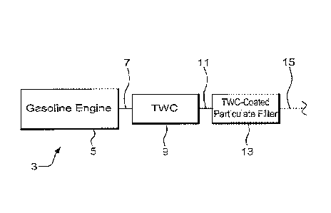
[0038] Turning to FIG. 1, an emissions treatment system 3 comprises a
gasoline
engine 5 that conveys exhaust through line 7 to an optional first TWC catalyst
9. In some
instances the first TWC catalyst can be smaller than otherwise needed because
of a
downstream TWC-coated particulate filter 13, which receives the exhaust stream
through
line 11. In instances where the TWC-coated particulate filter 13 provides full
TWC
functionality, the first TWC may not be needed. Line 15 can lead to further
treatment
components and/or to the tail pipe and out of the system. In other instances,
TWC-coated
CA 02796830 2012-10-18
WO 2011/133503
PCT/US2011/032978
particulate filter 13 contains a TWC catalyst loading that is designed to work
in conjunction
with the first TWC catalyst in order to meet emission requirements.
[0039] FIG. 2 depicts an integrated emission treatment system 30 comprises
a TWC
catalyst section 32, a particulate filter section 34, an optional NO, trap 36
and SCR 38.
During the treatment of an exhaust gas emission stream the exhaust gas flows
from an
engine through the integrated emission treatment system 30 for the treatment
and/or
conversion of exhaust gas emission contaminants such as unburned hydrocarbons
(HC),
carbon monoxide (CO), nitrogen oxides (NOõ), and particulate matter. The
exhaust gas
flows sequentially through the upstream TWC catalyst section 32, a particulate
filter section
34, an optional NO, trap 36 and SCR catalyst 38. In an alternative integrated
system, the
TWC catalyst can be coated onto the particulate filter, thereby eliminating a
section.
[0040] TWC catalysts that exhibit good activity and long life comprise one
or more
platinum group metals (e.g., platinum, palladium, rhodium, rhenium and
iridium) disposed
on a high surface area, refractory metal oxide support, e.g., a high surface
area alumina
coating. The support is carried on a suitable carrier or substrate such as a
monolithic carrier
comprising a refractory ceramic or metal honeycomb structure, or refractory
particles such
as spheres or short, extruded segments of a suitable refractory material. The
refractory metal
oxide supports may be stabilized against thermal degradation by materials such
as zirconia,
titania, alkaline earth metal oxides such as baria, calcia or strontia or,
most usually, rare
earth metal oxides, for example, ceria, lanthana and mixtures of two or more
rare earth
metal oxides. For example, see U.S. Pat, No, 4,171,288 (Keith). TWC catalysts
can also be
formulated to include an oxygen storage component.
[0041] Reference to a "support" in a catalyst washcoat layer refers to a
material that
receives precious metals, stabilizers, promoters, binders, and the like
through association,
dispersion, impregnation, or other suitable methods. Examples of supports
include, but are
not limited to, high surface area refractory metal oxides and composites
containing oxygen
storage components. High surface refractory metal oxide supports refer to
support particles
having pores larger than 20 A and a wide pore distribution. High surface area
refractory
metal oxide supports, e.g., alumina support materials, also referred to as
"gamma alumina"
or "activated alumina," typically exhibit a BET surface area in excess of 60
square meters
per gram ("m2/g"), often up to about 200 m2/g or higher. Such activated
alumina is usually
a mixture of the gamma and delta phases of alumina, but may also contain
substantial
amounts of eta, kappa and theta alumina phases. Refractory metal oxides other
than
CA 02796830 2012-10-18
WO 2011/133503
PCT/US2011/032978
11
activated alumina can be used as a support for at least some of the catalytic
components in a
given catalyst. For example, bulk ceria, zirconia, alpha alumina and other
materials are
known for such use. Although many of these materials suffer from the
disadvantage of
having a considerably lower BET surface area than activated alumina, that
disadvantage
tends to be offset by a greater durability of the resulting catalyst. "BET
surface area" has its
usual meaning of referring to the Brunauer, Emmett, Teller method for
determining surface
area by N2 adsorption.
100421 One or more embodiments include a high surface area refractory metal
oxide
support comprising an activated compound selected from the group consisting of
alumina,
alumina-zirconia, alumina-ceria-zirconia, lanthana-alumina, lanthana-zirconia-
alumina,
bail a-alumina, haria lanthana-alumina, baria lanthana-neodymia alumina, and
alumina-
ceria. Examples of composites containing oxygen storage components include,
but are not
limited to, ceria-zirconia and ceria-zirconia-lantliana. Reference to a "ceria-
zirconia
composite" means a composite comprising ceria and zirconia, without specifying
the
amount of either component. Suitable ceria-zirconia composites include, hut
are not limited
to, composites having, for example, 5%, 10%, 15%, 20%, 25%, 30%, 35%, 40%,
45%,
50%, 55%, 60%, 65%, 70%, 75%, 80%, 85%, 90% or even 95% of ceria content.
Certain
embodiments provide that the support comprises bulk ceria having a nominal
ceria content
of 100% (i.e., > 99% purity). In one or more embodiments, the support material
is
substantially free of alumina to maximize the oxygen storage capacity of the
catalyst.
Reference to "substantially free of alumina" means that alumina is present in
an amount of
no more than 5% of the total loading of the catalytic material. As desired,
the catalytic
material can be entirely free of alumina, that is, it can be alumina-free.
100431 As used herein, molecular sieves, such as zeolites, refer to
materials, which
may in particulate form support catalytic precious group metals, the materials
having a
substantially uniform pore distribution, with the mean pore size being no
larger than 20 A.
Reference to a "non-zeolite-support" in a catalyst washcoat layer refers to a
material that is
not a molecular sieve or zeolite and that receives precious metals,
stabilizers, promoters,
binders, and the like through association, dispersion, impregnation, or other
suitable
methods. Examples of such supports include, but are not limited to, high
surface area
refractory metal oxides.
[0044] Reference to "impregnated" means that a precious metal-containing
solution
is put into pores of a support. In detailed embodiments, impregnation of
precious metals is
CA 02796830 2012-10-18
WO 2011/133503
PCT/US2011/032978
12
achieved by incipient wetness, where a volume of diluted precious metal-
containing is
approximately equal to the pore volume of the support bodies. Incipient
wetness
impregnation generally leads to a substantially uniform distribution of the
solution of the
precursor throughout the pore system of the support. Reference to "intimate
contact"
includes having an effective amount of components in such contact (for
example, Pd and
OSC) on the same support, in direct contact, and/or in substantial proximity
such that the
OSC contacts oxygen components before the Pd component.
100451 The TWC catalytic material can comprise a first washcoat comprising
a
platinum group metal and an oxygen storage component composite material.
Optionally,
the filter can be coated before any platinum group metal-containing washcoat
with an under
washcoat comprising ceria and optionally a stabilizer selected from the group
consisting of
lanthanum, zirconium, praseodymium, yttrium, and neodymium. The oxygen storage
component can he preset in an amount in the range of 0.5 to 4.0 g/in3 (30.5
g/L to 244 g/L).
One embodiment provides the TWC catalytic material being substantially free of
alumina.
Another embodiment provides that the TWC catalytic material is free of NOx
trapping
components. In yet another embodiment, the TWC catalytic material stores at
least 200
mg/L of oxygen after a full useful life aging.
[0046] In a zoned embodiment, the catalyzed particulate filter comprises an
upstream zone and a downstream zone that both comprise a palladium component,
wherein
the upstream zone comprises the palladium component in an amount that is
greater than the
amount of the palladium component in the downstream zone. One example provides
that
there is 20-100g/ft3 (0.7 to 3.5 g/L) of palladium in the upstream zone and 1-
20 g/ft3 for
downstream.
Particulate Trap
[0047] Reference to particulate trap means a filter so sized and configured
to trap
particulates generated by the combustion reactions in the direct injection
gasoline engine.
Trapping of particulates can occur, for example, by use of a particulate (or
soot) filter, by
use of a flow-through substrate having an internal tortuous path such that a
change in
direction of flow of the particulates causes them to drop out of the exhaust
stream, by use of
a metallic substrate, such as a corrugated metal carrier, or by other methods
known to those
skilled in the art. Other filtration devices may be suitable, such as a pipe
with a roughened
surface that can knock particles out of the exhaust stream. A pipe with a bend
may also be
suitable.
CA 02796830 2012-10-18
WO 2011/133503
PCT/US2011/032978
13
[0048] With reference to filters, FIG, 3 depicts a perspective view of an
exemplary
wall flow filter substrate suitable for a particulate filter. Wall flow
substrates useful for
supporting the TWC or oxidation catalyst compositions have a plurality of
fine,
substantially parallel gas flow passages extending along the longitudinal axis
(or axial
length) of the substrate. Typically, each passage is blocked at one end of the
substrate body,
with alternate passages blocked at opposite end-faces. Such monolithic
carriers may
contain up to about 300 flow passages (or "cells") per square inch of cross
section, although
far fewer may be used. For example, the carrier may have from about 7 to 300,
more
usually from about 200 to 300, cells per square inch ("cpsi"). The cells can
have cross
sections that are rectangular, square, circular, oval, triangular, hexagonal,
or are of other
polygonal shapes. Wall flow substrates typically have a wall thickness between
0.008 and
0.016 inches. Specific wall flow substrates have a wall thickness of between
0.010 and
0.012 inches. Axial zoning may be desirable such that a coating is provided
along an axial
length of the filter. On the inlet side, as measured from the upstream end 54,
a coating may
extend up to 50% of the axial length (e.g., 1 to 49.9%, or 10 to 45%), 50 to
75% of the axial
length, or even 100% of the axial length. On the outlet side, as measured from
the
downstream end 56, a coating may extend up to 50% of the axial length (e.g., 1
to 49.9%, or
to 45%), 50 to 75% of the axial length, or even 100% of the axial length.
[0049] FIGS. 3 and 4 illustrate a wall flow filter substrate 50 which has a
plurality
of passages 52. The passages are tubularly enclosed by the internal walls 53
of the filter
substrate. The substrate has an inlet or upstream end 54 and an outlet or
downstream end
56. Alternate passages are plugged at the inlet end with inlet plugs 58 and at
the outlet end
with outlet plugs 60 to form opposing checkerboard patterns at the inlet 54
and outlet 56. A
gas stream 62 enters at upstream end 54 through the unplugged channel inlet
64, is stopped
by outlet plug 60 and diffuses through channel walls 53 (which are porous) to
the outlet side
66. A coating on the inlet side of the filter means that the coating resides
on or within the
walls 53 such that the gas stream 62 contacts the inlet coating first. A
coating on the outlet
side of the filter means that the coating resides on or within the walls 53
such that the gas
stream 62 contacts the outlet coating after the inlet coating. The gas cannot
pass back to the
inlet side of walls because of inlet plugs 58.
[0050] Wall flow filter substrates can be composed of ceramic-like
materials such as
cordierite, alumina, silicon carbide, aluminum titanate, mullite, or of
refractory metal. Wall
flow substrates may also be formed of ceramic fiber composite materials.
Specific wall
CA 02796830 2012-10-18
WO 2011/133503 PCT/US2011/032978
14
flow substrates are formed from cordierite, silicon carbide, and aluminum
tita.nate. Such
materials are able to withstand the environment, particularly high
temperatures, encountered
in treating the exhaust streams.
[0051] Wall flow substrates for use in the inventive system can include
thin porous
walled honeycombs (monoliths) through which the fluid stream passes without
causing too
great an increase in back pressure or pressure across the article. Ceramic
wall flow
substrates used in the system can be formed of a material having a porosity of
at least 40%
(e.g., from 40 to 70%). Useful wall flow substrates can have an overall mean
pore size of
or more microns. Certain wall flow substrates have an asymmetric pore size
distribution
having a first mean pore size of no more than 30 irn and a second mean pore
size of no less
than 30 pm. In a specific embodiment, the substrates can have a porosity of at
least 55%
and a first mean pore size in the range of 10 to 30 microns and a second mean
pore size in
the range of 31 to 100 microns. When substrates with these porosities and
these mean pore
sizes are coated with the techniques described below, adequate levels of TWC
compositions
can be loaded onto the substrates to achieve excellent hydrocarbon, CO, and/or
NOx
conversion efficiency. These substrates are still able retain adequate exhaust
flow
characteristics, i.e., acceptable back pressures, despite the catalyst
loading.
[0052] The porous wall flow filter used in this invention is catalyzed in
that the wall
of the element has thereon or contained therein one or more catalytic
materials. Catalytic
materials may be present on the inlet side of the element wall alone, the
outlet side alone,
both the inlet and outlet sides, or the wall itself may consist all, or in
part, of the catalytic
material. This invention includes the use of one or more washeoats of
catalytic materials
and combinations of one or more washcoats of catalytic materials on the inlet
and/or outlet
walls of the element.
[0053] To coat the wall flow filters with the TWC or oxidation catalyst
composition,
the substrates are immersed vertically in a portion of the catalyst slurry
such that the top of
the substrate is located just above the surface of the slurry. In this manner
slurry contacts
the inlet face of each honeycomb wall, but is prevented from contacting the
outlet face of
each wall. The sample is left in the slurry for about 30-60 seconds. The
filter is removed
from the slurry, and excess slurry is removed from the wall flow filter first
by allowing it to
drain from the channels, then by blowing with compressed air (against the
direction of
slurry penetration), and then by pulling a vacuum from the direction of slurry
penetration.
By using this technique, the catalyst slurry permeates the walls of the
filter, yet the pores are
CA 02796830 2012-10-18
WO 2011/133503
PCT/US2011/032978
not occluded to the extent that undue back pressure will build up in the
finished filter. As
used herein, the term "permeate" when used to describe the dispersion of the
catalyst slurry
on the filter, means that the catalyst composition is dispersed throughout the
wall of the
filter.
[0054] The coated filters are dried typically at about 100 C and calcined
at a higher
temperature (e.g., 300 to 450 C and up to 590 C). After calcining, the
catalyst loading can
be determined through calculation of the coated and uncoated weights of the
filter. As will
be apparent to those of skill in the art, the catalyst, loading can be
modified by altering the
solids content of the coating slurry. Alternatively, repeated immersions of
the filter in the
coating slurry can be conducted, followed by removal of the excess slurry as
described
above.
[0055] With reference to a metallic substrate, a useful substrate may be
composed of
one or more metals or metal alloys. The metallic carriers may be employed in
various
shapes such as corrugated sheet or monolithic form. Specific metallic supports
include the
heat resistant metals and metal alloys such as titanium and stainless steel as
well as other
alloys in which iron is a substantial or major component. Such alloys may
contain one or
more of nickel, chromium and/or aluminum, and the total amount of these metals
may
advantageously comprise at least 15 wt % of the alloy, e.g., 10-25 wt % of
chromium, 3-8
wt % of aluminum and up to 20 wt % of nickel. The alloys may also contain
small or trace
amounts of one or more other metals such as manganese, copper, vanadium,
titanium and
the like. The surface of the metal carriers may be oxidized at high
temperatures, e.g.,
1000 C and higher, to improve the resistance to corrosion of the alloys by
forming an oxide
layer on the surfaces of the carriers. Such high temperature-induced oxidation
may enhance
adherence of a catalytic material to the carrier.
Preparation of Catalyst Composite Washcoats
[0056] The catalyst composites may be formed in a single layer or multiple
layers.
In some instances, it may be suitable to prepare one slurry of catalytic
material and use this
slurry to form multiple layers on the carrier. The composites can readily
prepared by
processes well known in the prior art. A representative process is set forth
below. As used
herein, the term "washcoat" has its usual meaning in the art of a thin,
adherent coating of a
catalytic or other material applied to a substrate carrier material, such as a
honeycomb-type
carrier member, which is sufficiently porous to permit the passage there
through of the gas
CA 02796830 2012-10-18
WO 2011/133503
PCT/US2011/032978
16
stream being treated. A "washcoat layer," therefore, is defined as a coating
that is
comprised of support particles. A "catalyzed washcoat layer" is a coating
comprised of
support particles impregnated with catalytic components.
[0057] The catalyst composite can be readily prepared in layers on a
carrier. For a
first layer of a specific washcoat, finely divided particles of a high surface
area refractory
metal oxide such as gamma alumina are slurried in an appropriate vehicle,
e.g., water, To
incorporate components such as precious metals (e.g., palladium, rhodium,
platinum, and/or
combinations of the same), stabilizers and/or promoters, such components may
be
incorporated in the slurry as a mixture of water soluble or water-dispersible
compounds or
complexes. Typically, when palladium is desired, the palladium component is
utilized in
the form of a compound or complex to achieve dispersion of the component on
the
refractory metal oxide support, e.g., activated alumina. The term "palladium
component"
means any compound, complex, or the like which, upon calcination or use
thereof,
decomposes or otherwise converts to a catalytically active form, usually the
metal or the
metal oxide. Water-soluble compounds or water-dispersible compounds or
complexes of
the metal component may be used as long as the liquid medium used to
impregnate or
deposit the metal component onto the refractory metal oxide support particles
does not
adversely react with the metal or its compound or its complex or other
components which
may be present in the catalyst composition and is capable of being removed
from the metal
component by volatilization or decomposition upon heating and/or application
of a vacuum.
In some cases, the completion of removal of the liquid may not take place
until the catalyst
is placed into use and subjected to the high temperatures encountered during
operation.
Generally, both from the point of view of economics and environmental aspects,
aqueous
solutions of soluble compounds or complexes of the precious metals are
utilized. For
example, suitable compounds are palladium nitrate or rhodium nitrate.
100581 A suitable method of preparing any layer of the layered catalyst
composite of
the invention is to prepare a mixture of a solution of a desired precious
metal compound
(e.g., palladium compound) and at least one support, such as a finely divided,
high surface
area, refractory metal oxide support, e.g., gamma alumina, which is
sufficiently dry to
absorb substantially all of the solution to form a wet solid which later
combined with water
to form a coatable slurry. In one or more embodiments, the slurry is acidic,
having, for
example, a pH of about 2 to less than about 7. The pH of the slurry may be
lowered by the
addition of an adequate amount of an inorganic or an organic acid to the
slurry.
CA 02796830 2012-10-18
WO 2011/133503 PCT/US2011/032978
17
Combinations of both can be used when compatibility of acid and raw materials
is
considered. Inorganic acids include, but are not limited to, nitric acid,
Organic acids
include, but are not limited to, acetic, propionic, oxalic, malonic, succinic,
glutamic, adipic,
maleic, fumaric, phthalic, tartaric, citric acid and the like. Thereafter, if
desired, water-
soluble or water-dispersible compounds of oxygen storage components, e.g.,
cerium-
zirconium composite, a stabilizer, e.g., barium acetate, and a promoter, e.g.,
lanthanum
nitrate, may be added to the slurry.
[0059] In one embodiment, the slurry is thereafter comminuted to result in
substantially all of the solids having particle sizes of less than about 30
microns, i.e.,
between about 0.1-15 microns, in an average diameter. The comminution may be
accomplished in a ball mill, circular mill, or other similar equipment, and
the solids content
of the slurry may be, e.g., about 20-60 wt. %, more particularly about 30-40
wt. %.
[00601 Additional layers, i.e., the second and third layers may be prepared
and
deposited upon the first layer in the same manner as described above for
deposition of the
first layer upon the carrier.
EXAMPLES
[0061] The following non-limiting examples shall serve to illustrate the
various
embodiments of the present invention. In each of the examples, the carrier is
cordierite,
EXAMPLE 1
COMPARATIVE
[0062] A three-way conversion (TWC) catalyst on a honeycomb flow through
substrate with a washcoat loading of 1 g/in3 (61 g/L) was prepared. The flow
through
substrate had a size of 4.66*5", 300/12 cpsi, 1.4 L volume, 30 g/ft3 platinum
group metals
(PGM), and a PGM ratio of Pt/Pd/Rh of 0/27/3.
EXAMPLE 2
[0063] A particle filter of low porosity having a three-way conversion
(TWO)
catalyst within the substrate wall was prepared at washcoat loadings of 1
g/in3 (61 g/L), 2
Win3 (122 g/L (2 g/in3), and 3 g/in3 (183 g/L). The filter substrate had a
size of 4.66*5",
300/12 cpsi, 1.4 L volume, 30 g/ft3 platinum group metals (PGM), and a PGM
ratio of
Pt/Pd/Rh of 0/27/3. The filter substrate had a 45% porosity and a mean pore
size of 13 um.
CA 02796830 2012-10-18
WO 2011/133503
PCT/US2011/032978
18
EXAMPLE 3
[0064] A particle filter of high porosity having a three-way conversion
(TWC)
catalyst within the substrate wall was prepared at washcoat loadings of 1
g/in3 (61 g/L), 2
Win3 (122 g/L ), and 3 g/in3 (183 g/L). The filter substrate had a size of
4.66*5", 300/12
cpsi, 1.4 L volume, 30 g/ft3 platinum group metals (P GM), and a PGM ratio of
Pt/Pd/Rh of
0/27/3. The filter substrate had a 65% porosity and a mean pore size of 20 pm.
EXAMPLE 4
100651 The composites of Examples 1, 2, and 3 each having 1g/in3 (61 g/L)
were
aged for 4 hours under hydrothermal oven aging at 900 C in 2% 02, 10% H20, and
balance
N2. Under New European Drive Cycle (NEDC) conditions and a 1.6L engine with
composite located downstream of the gasoline direct injection engine in a
close-coupled
position, particulate number was measured using PMP protocol (Table 1).
Emissions of
non-methane hydrocarbons (NMHC), total hydrocarbons (HC), carbon monoxide
(CO), and
NOx were also measured (Table I).
Table
Example 1 Example 2 Example 3 Euro 6 Std
Comparative (low porosity) (high porosity)
Particulate 1.61E+12 1.91E+11 7.08E+11 6.00E+11*
Number (#/km)
NMHC (g/lcm) 0.06 0.155 0.134 0.068
THC (gikm) 0.069 0.169 0.146 0.1
C0/10 (g/km) 0.0313 0.07 0.0585 0.1
NOx (g/ktn) 0.124 0.244 0.228 0.060 .
As proposed by the European Commission.
100661 There is significantly lower TWC catalytic efficiency for the coated
filters of
Examples 2 and 3 as compared to comparative Example 1. The comparative flow
through
substrate of Example 1, however, shows no filtration efficiency. The low
porosity filter of
Example 2 at a washeoat loading of 1 g/in3 (61 g/L) met the Euro 6 standard.
Backpressure
of Examples 2 and 3 were evaluated during the EUDC segment of the NEDC. There
was
significantly higher backpressure for Example 2 as compared to Example 3.
EXAMPLE 5
[0067] The composites of Example 3 at varying wad-twat loadings were aged
for 80
hours under I000 C exothermic aging. Under New European Drive Cycle (NEDC)
CA 02796830 2012-10-18
WO 2011/133503
PCT/US2011/032978
19
conditions and a 1.6L engine with composite located downstream of the gasoline
direct
injection engine in a close-coupled position, particulate number was measured
using PMP
protocol (Table 2a). Emissions of particulate mass, total hydrocarbons (HC),
carbon
monoxide (CO), and NOx were also measured (Table 2a).
Table 2a
Example 3 Example 3 Example 3 Euro 6 Std
1 Win3 2 Win3 3 g/in3
(61 g/L) (122 g/L) (183 g/L)
Particulate 4,09E+12 1,30E+11 8.3E+10 6.00E+11'
Number (1-1/km)
Particulate 0.0005 0.0006 0.0007 0.0045
Mass (g/km)
HC (g/km) 0.335 0.294 0.269 0.1
C0/10 (g/km) 0.1744 0.1585 0.1366 0.1
NOx (g/km) 0.425 0.385 0.289 0.060
As proposed by the European Commission.
[0068] Increasing the washcoat loading moved the high porosity filter well
under the
Euro 6 particulate number regulation. The particulate emissions of all of the
filters easily
met the Euro 6 standard. Higher washcoat loading reduced emissions, especially
NOx.
Backpressure for Example 3, high porosity filter, at 2 g/in3 loading was
similar to an
uncoated filter of low porosity as provided in Example 2.
[0069] Filter substrates of 4.66x4.5" of the porosity of the loadings of
Example 3
high porosity filters were also aged for 80 hours under 1000 C exothermic
aging and their
oxygen storage capacities were tested. Table 2b provides a summary of the
data, which
were calculated based in front/rear sensor delay time rich/lean at 501 C/26.1
kg/h.
Table 2b
Example 3 Example 3 Example 3
1 g/in3 2 Win3 3 g/in3
(61 WL) (122 g/L) (183 g/L)
Oxygen Storage 12.0 20,9 28.9
(mg)
[0070] Increasing the washcoat loading also increases the oxygen storage
capability.
CA 02796830 2012-10-18
WO 2011/133503 PCT/US2011/032978
EXAMPLE 6
[0071] The coated filters having 1 g/in3 (122 g/L) and 3 g/in3 (183 g/L)
were
combined with close coupled TWC catalyst on a flow through substrate having 60
g/ft3
precious group metals. These were tested for CO2 emissions along with
comparative
systems having either only the close coupled TWC catalyst on a flow through
substrate
(CC) or the close coupled TWC catalyst on a flow through substrate in
combination with an
under floor (UF) TWC. The results for individual NEDC evaluations on a 2.0L
engine with
composite located downstream of the gasoline direct injection engine in under
floor
position, are provided in Table 3.
Table 3
CO2 CC + CC+ CC only CC + UF
emissions Example 3 Example 3 TWCs
(g/k11[1) 1 g/in3 3 g/in3
(61 g/L) (183 g/L)
Test # 1 186.89 183.04 186.5 183.16
Test # 2 184.03 182.9 185.97 184.3
Test # 3 182.39 184.4 185.04 182.23
Test If 4 180.82 _ 182.7
Test # 5 181.6
[0072] Similar levels of CO2 emissions for close coupled TWC catalyst in
combination with coated particulate filters as compared to TWC catalyst-only
systems
indicated no fuel penalty under NEDC test conditions.
EXAMPLE 7
[00731 The systems of Example 6, with the addition of the 2 g/in3 (122 g/L)
loading
of Example 3, were then aged for 80 hours under 1000 C exothermic aging. Under
New
European Drive Cycle (NEDC) conditions and a 2.0L engine with composite
located
downstream of the gasoline direct injection engine in under floor position,
total
hydrocarbons (HC), carbon monoxide (CO), and NOx were measured (Table 4).
Table 4
CC + CC+ CC+ CC only CC + UF
Example 3 F,xample 3 Example 3
1 g/in3 2 g/in3 3 g/in3
(61 g/L) (122 g/L) (183 g/L)
CA 02796830 2012-10-18
WO 2011/133503
PCT/US2011/032978
21
HC (g/km) 0.0428 0.0411 0.0370 0.0472 0,0283
C0/10 0.0579 0.0601 0.0592 0.0640 0.0444
(g/101[1)
NOx (g/lun) 0.0498 0.0459 0.0449 0.0615 0.0343
[0074] Addition of underfloor (UF) TWC or coated particulate filter allowed
the
system to meet Euro 6 emission standards.
EXAMPLE 8
[0075] A system of a 60 gift3 platinum group metal TWC catalyst in a close-
coupled
position and a 3 g/in3 coated particulate filter was aged for 80 hours under
1000 C
exothermic aging and was tested under repeated NEDC tests using a 2.0L engine.
Table 5
shows particulate numbers for the coated filter after 3 tests. This coated
filter was then
subjected to a regeneration activity of 15 minutes simulated highway driving,
multiple
accelerations and fuel cuts having a maximum velocity of ¨ 130 km/h and
reaching 700 C.
NEDC tests were then repeated 4 more times.
Table 5
Particulate Example 3
Number g/in3
(#/km) ( g/L)
Test # 1 2.53E+11
Test # 2 4.96E+10
Test # 3 2.00E+10
Regeneration event.
Test # 1 b 2.35E+11
Test fi 2b 4.89E+10
Test # 3b 2.68E+10
Test It 4b 1.68E+10
[0076] Table 5 indicates that the filtration efficiency of the particulate
filter
improved over time. In addition, it is shown that the coated filter can be
regenerated under
expected highway driving conditions. Emissions data was also obtained that
showed no
effect on HC, CO, or NOx conversion after the regeneration event.
CA 02796830 2012-10-18
WO 2011/133503
PCT/US2011/032978
22
EXAMPLE 9
[0077] Coated particulate filters of varying loadings of Example 3 were
tested under
repeated NEDC tests using a 2.0L engine with composite located downstream of
the
gasoline direct injection engine in an under floor position. Table 6 shows
particulate
numbers for the coated filters.
Table 6
CC + CC+ CC+
Example 3 Example 3 Example 3
1 g/in3 2 g/in3 3 g/in3
(61 g/L) (122 g/L) (183 g/L)
Test # 1 6.74E+11 3.33E+11 2.35E+11
Test # 2 5.26E+11 7.08E+10 4.89E+10
Test # 3 5.76E+11 - 2.68E+10
Test # 4 5.52E+11 - 1.68E+10
[0078] Filtration efficiency of high porosity filter in underfloor position
improved as
washcoat loading increased.
EXAMPLE 10
[0079] A catalyzed particle filter having a three-way conversion (TWC)
catalyst on
or within the substrate wall was prepared at a washcoat loadings of 2 g/in3
(122 g/L) with
varying zoning configurations. The uncoated filter substrate had a mean pore
size of 20 t.tm
and had size of 4.66*5", 300/12 cpsi, 1.4 L volume. The washcoat contained 60
gift3
platinum group metals (PGM), and a PGM ratio of Pt/Pd/Rh of 0/57/3. Table 7
provides a
summary of the washcoat of Examples 10A, 10B, and 10C and resulting filter in
comparison to an uncoated filter. With respect to porosity, sections of the
filter were tested,
including front, middle, and rear portions. The middle portion was a small
fraction of the
overall substrate. Porosity of the filter is usually obtained from an average
of the porosity
measurements of the front and rear portions. With respect to the d50 and d90
particle sizes
recited for Example 10C, which had an asymmetric particle size distribution,
they
correspond to the sum of two monomodal distributions.
Table 7
Example 10A Example 10B Example 10C Uncoated
CA 02796830 2012-10-18
WO 2011/133503 PCT/US2011/032978
23
Filter
Washcoat Loading 2 (122) 2 (122) 2 (122)
g/in3 (g/L)
Particles Character single average single two average
size average size sizes
Substantially Substantially asymmetric
symmetric symmetric distribution
distribution distribution
Washcoat Particles
d50 (pm) 2.04 2.04 3.19
frequency 94 94 95
Max = 94 Max = 94 Max = 99
Washcoat Particles
d90 0,Lrn) 5.48 5.48 16.37
frequency 45 45 48
Zoning 100% inlet 50% inlet 100% inlet
100% outlet 50% outlet 100% outlet
Porosity
Full porosity front 57.0% 58.8% 59.5% 62.5%
(porosity (5.7%) (7.4%) (4%) (9.7%)
contribution of
pores larger than
30p.m)
Full porosity 56.5% 54.4% 61.2% 63.5%
middle (5.1%) (5.0%) (4.1%) (10.1%)
(porosity
contribution of
pores larger than
30[tm)
Full porosity rear 57.5% 58.1% 60.9% 63.0%
(porosity (5.8%) (7.2%) (3.7%) (10.6%)
contribution of
pores larger than
301_tm)
EXAMPLE 11
[0080] The catalyzed filters of Example 10 were aged for 80 hours under
1000 C
exothermic aging. Under New European Drive Cycle (NEDC) conditions and a 1.6L
engine
with composite located downstream of the gasoline direct injection engine in
close-coupled
position, particulate number was measured using PMP protocol (Table 8).
Emissions of
particulate mass, total hydrocarbons (HC), carbon monoxide (CO), and NOx were
also
measured (Table 8). Impact of porosity on backpressure is provided in FIG. 5.
CA 02796830 2012-10-18
WO 2011/133503 PCT/US2011/032978
24
Table 8
Example 10A Example 10B Example 10C Euro 6 Std
Particulate 3.97E+11 1.81E+11 1.73E+11 6.00E+11*
Number (#/km)
NMHC (g/km) 0.098 0.095 0.092 0.068
THC (g/km) 0.109 0.106 0.103 0.1
C0/10 (g/km) 0.0982 0.0955 0.0903 0.1
NOx (g/km) 0.106 0.102 0.093 0.060
As proposed by the European Commission.
[0081] The data of Table 8 indicate that the higher porosity catalyzed
filter of
Example 10C having a washcoat that is coated 100% on the inlet and 100% on the
outlet
having two average particles sizes provides lower NOx, CO, and HC conversion
at a
constant overall loading as compared to Example 10A. Filtration efficiency is
also
improved with the waslicoat of Example 10C.
EXAMPLE 12
[0082] A catalyzed particle filter having a three-way conversion (TWC)
catalyst on
or within the substrate wall was prepared at a washcoat loadings of 2 g/in3
(122 g/L) with
varying zoning configurations. The uncoated filter substrate had a mean pore
size of 20 nm
and had size of 4.66*5", 300/12 cpsi, 1.4 L volume. The washcoat contained 60
g/ft3
platinum group metals (P GM), and a PGM ratio of Pt/Pd/Rh of 0/57/3. Table 9
provides a
summary of the washcoat of Examples 12A, 12B, 12C, and 12D and resulting
filter. The
uncoated filter is that shown in Table 7. With respect to porosity, sections
of the filter were
tested, including front, middle, and rear portions. The middle portion was a
small fraction
of the overall substrate. Porosity of the filter is usually obtained from an
average of the
porosity measurements of the front and rear portions. With respect to the d50
and d90
particle sizes recited for Examples 12A, I2B, 12C, and 12D, which had an
asymmetric
particle size distributions, they correspond to the sum of two monomodal
distributions.
Table 9
Example Example 12B Example I2C Example 12D
12A
Washcoat Loading 2 (122) 2.5 (152.5) 2 (122) 2.5 (152.5)
CA 02796830 2012-10-18
WO 2011/133503
PCT/US2011/032978
gjjflJ (g/L)
Particles Character two average two average two average two average
sizes sizes sizes sizes
asymmetric asymmetric asymmetric asymmetric
distribution distribution distribution distribution
Washcoat Particles
d50 (gm) 2.23 2,23 2.23 2.23
frequency
Washcoat Particles
d90 (p.m) 6.6 6. 6.6 6.6
frequency
Zoning 50% inlet 50% inlet 100% inlet 100% inlet
50% outlet 50% outlet 100% outlet 100% outlet
Porosity
Full porosity 61.2% 62.4% 60.4% 60.0%
front (5.3%) (4.8%) (5.5%) (3.7%)
(porosity
contribution of
pores larger
than 30pm)
Full porosity 56.4% 61.9% 60.1% 60.1%
middle (2.7%) (3.1%) (5.4%) (3.2%)
(porosity
contribution of
pores larger
than 30pm)
Full porosity 61.7% 62.4% 61.7% 59.9%
rear (6.0%) (4.8%) (5,9%) (4.0%)
(porosity
contribution of
pores larger
than 30rtm)
EXAMPLE 13
[0083] The catalyzed filters of Example 12 are aged for 80 hours under 1000
C
exothermic aging. Under New European Drive Cycle (NEDC) conditions and a 1.6L
engine
with composite located downstream of the gasoline direct injection engine in
close-coupled
position, particulate number is measured using PMP protocol. Emissions of
particulate
mass, total hydrocarbons (1-1C), carbon monoxide (CO), and NOx are also
measured.
CA 02796830 2012-10-18
WO 2011/133503
PCT/US2011/032978
26
EXAMPLE 14
[0084] A particle filter having a catalytic material is prepared using two
coats: a first
inlet coat and a second inlet coat. The three-way conversion (TWC) catalyst
composite
contains palladium such that an upstream zone has more palladium than a
downstream zone.
The coats are prepared as follows:
First Inlet Coat
[0085] The components present in the first inlet coat are a ceria-zirconia
composite
with 45% ceria by weight and palladium. The first inlet coat is provided along
the entire
length of the filter. After coating, the filter plus the first inlet coat are
dried and then
calcined at a temperature of 550 C for about 1 hour.
Second Inlet Coat
100861 The second inlet coat comprises palladium, which is applied as a dip
or as a
washcoat slurry along a length of the filter starting from the upstream end to
form an
upstream zone. After application, the filter plus the first inlet coat and
second inlet coat are
dried and then calcined at a temperature of 550 C for about 1 hour.
EXAMPLE 15
[0087] A particle filter having a catalytic material is prepared using two
coats: an
inlet coat and an outlet coat. The three-way conversion (TWC) catalyst
composite contains
palladium and rhodium. The coats are prepared as follows:
Inlet Coat
[0088] The component present in the first inlet coat is palladium, and this
coat is
free of ceria. After coating, the filter plus the inlet coat are dried and
then calcined at a
temperature of 550 C for about 1 hour.
Outlet Coat
[0089] The outlet coat comprises rhodium and a ceria-zirconia composite
with 45%
ceria by weight. After application, the filter plus the inlet coat and the
outlet coat are dried
and then calcined at a temperature of 550 C for about 1 hour.
EXAMPLE 16
[0090] A particle filter having a catalytic material is prepared using two
coats: an
inlet coat and an outlet coat. The three-way conversion (TWC) catalyst
composite contains
platinum and rhodium. The coats are prepared as follows:
CA 02796830 2012-10-18
WO 2011/133503 PCT/US2011/032978
27
Inlet Coat
[0091] The components present in the first inlet coat are platinum and
barium as a
NOx trapping material. After coating, the filter plus the inlet coat are dried
and then
calcined at a temperature of 550 C for about 1 hour.
Outlet Coat
[0092] The outlet coat comprises rhodium and a ceria-zirconia composite
with 45%
ceria by weight. After application, the filter plus the inlet coat and the
outlet coat are dried
and then calcined at a temperature of 550 C for about 1 hour.
EXAMPLE 17
[0093] A particle filter having a catalytic material is prepared using two
coats: an
inlet coat and an outlet coat. The three-way conversion (TWC) catalyst
composite contains
platinum and palladium. The coats are prepared as follows:
Inlet Coat
[0094] The component present in the first inlet coat is palladium, and this
coat is
ceria-free. After coating, the filter plus the inlet coat are dried and then
calcined at a
temperature of 550 C for about 1 hour.
Outlet Coat
[0095] The outlet coat comprises platinum, a ceria-zirconia composite with
45%
ceria by weight, and a zeolite that is a hydrocarbon trapping material. After
application, the
filter plus the inlet coat and the outlet coat are dried and then calcined at
a temperature of
550 C for about 1 hour.
EXAMPLE 18
[0096] A particle filter having a catalytic material is prepared using one
inlet coat.
The inlet coat has a bimodal particle size distribution, such that a first
mean particle size is
30 um or less and a second particle size is more than 30 pin. The particle
filter has a
bimodal pore size distribution, such that a first mean pore size is 30 pm or
less and a second
pore size is more than 30 um.
EXAMPLE 19
[0097] A particle filter having a catalytic material is prepared using two
inlet coats.
The first inlet coat has a first monomodal particle size distribution, with a
mean particle size
is 30 um or less, which is coated along 50% of the inlet from the upstream
end. The second
CA 02796830 2012-10-18
WO 2011/133503
PCT/US2011/032978
28
inlet coat has a second monomodal particle size distribution, with a mean
particle size is
more than 30 um, which is coated the entire length of the filter. The particle
filter has a
bimodal pore size distribution, such that a first mean pore size is 30 j.tm or
less and a second
pore size is more than 30 p.m or more.
EXAMPLE 20
[00981 A particle filter of EXAMPLE 5 was further prepared with a second
inlet
coat has a third monomodal particle size distribution, with a mean particle
size of about 15
Inn, which is coated along 50% of the inlet from the upstream end.
EXAMPLE 21
COMPARATIVE
[0099] A particle filter having a catalytic material is prepared using two
coats: an
inlet coat and an outlet coat. A three-way conversion (TWC) catalytic material
is formed
from a washcoat of palladium, rhodium, alumina, and ceria-zirconia having a
monomodal
particle size distribution with a mean particle size of 3.5gm. The coats are
prepared as
follows:
Inlet Coat
[00100] The inlet side of the filter is coated with the TWC catalytic
material
washcoat at a loading of 0.5 g/in3. After coating, the filter plus the inlet
coat are dried and
then calcined at a temperature of 550 C for about 1 hour.
Outlet Coat
[00101] The outlet side of the filter is coated with the same washcoat and
loading as
the inlet side. After application, the filter plus the inlet coat and outlet
coat are dried and
then calcined at a temperature of 550 C for about 1 hour.
EXAMPLE 22
COMPARATIVE
1001021 A particle filter having a catalytic material is prepared using one
inlet coat.
The three-way conversion (TWC) catalyst composite is formed from a washcoat of
palladium, rhodium, alumina, and ceria-zirconia having a monomodal particle
size
distribution with a mean particle size of 3.5um. The inlet coat is prepared as
follows:
CA 02796830 2012-10-18
WO 2011/133503
PCT/US2011/032978
29
Inlet Coat
[00103] The inlet side of the filter is coated with the TWC washcoat at a
loading of
1.0 g/in3. After coating, the filter plus the inlet coat are dried and then
calcined at a
temperature of 550 C for about I hour.
EXAMPLE 23
[00104] A particle filter having a three-way conversion (TWC) catalytic
material is
prepared using one inlet coat. The inlet coat is formed from a washcoat in an
amount in the
range of 0.5 to 4,0 g/in3, where the washcoat comprises palladium, rhodium,
and ceria-
zirconia. This washcoat is substantially free of alumina, such that there is
up to only 5%
alumina by weight of the total catalytic material loading.
EXAMPLE 24
[00105] A particle filter having a three-way conversion (TWC) catalytic
material is
prepared using two inlet coats. The first inlet coat is formed from a washcoat
in an amount
in the range of 0.25 to 2.0 g/in3, where the washcoat comprises palladium and
a ceria-
zirconia. The second inlet coat is formed from a washcoat in an amount in the
range of 0.25
to 2.0 g/in3, where the washcoat comprises rhodium and a ceria-zirconia that
is either the
same or different from the ceria-zirconia of the first inlet coat, Both
washcoats are
substantially free of alumina, such that there is up to only 5% alumina by
weight of the total
catalytic material loading.
[00106] Reference throughout this specification to "one embodiment,"
"certain
embodiments," "one or more embodiments" or "an embodiment" means that a
particular
feature, structure, material, or characteristic described in connection with
the embodiment is
included in at least one embodiment of the invention. Thus, the appearances of
the phrases
such as "in one or more embodiments," "in certain embodiments," "in one
embodiment" or
"in an embodiment" in various places throughout this specification are not
necessarily
refen=ing to the same embodiment of the invention. Furthermore, the particular
features,
structures, materials, or characteristics may be combined in any suitable
manner in one or
more embodiments.
[00107] The invention has been described with specific reference to the
embodiments
and modifications thereto described above. Further modifications and
alterations may occur
CA 02796830 2012-10-18
WO 2011/133503
PCT/US2011/032978
to others upon reading and understanding the specification. It is intended to
include all such
modifications and alterations insofar as they come within the scope of the
invention.