Note: Descriptions are shown in the official language in which they were submitted.
CA 02796846 2015-04-16
1
Object proximity warning system and method
Technical Field
The invention relates to a system and a
method for issuing proximity warnings.
Background Art
Surface mines and similar sites or areas are
generally operated by means of a large number of vehi-
cles, some of which may be exceedingly large and diffi-
cult to control and have very limited visibility for the
operator.
It has been proposed to use GNSS-devices
(GNSS - global navigation satellite system, such as GPS)
on board of the vehicles and other objects, such as
cranes, to generate proximity warnings in order to reduce
the risk of collisions between vehicles. Such a system is
e.g. described in WO 2004/047047. The system is based on
devices mounted to the objects. Each device comprises a
GNSS receiver, a control unit deriving positional data
using the signal of the GNSS receiver, a radio circuit
for wireless exchange of the positional data with the
other devices, and an output device for outputting prox-
imity warnings.
Another approach based on GNNS receivers is
disclosed in WO 2010/142046.
Other approaches for extra-large vehicles are
introduced in "Avoiding accidents with mining vehicles",
retrieved and accessed from/on the Internet at
http://www.flir.com/uploadedFiles/Eurasia/MMC/Appl_Storie
s/AS 0020 EN.pdf on February 2, 2010. Accordingly, some
of the vehicles are equipped with an 8m radar system
CA 02796846 2016-04-07
2
which warns the driver when something is in his path. In
addition to the radar system GPS traffic alert systems
can be installed which warns the driver of any possible
accidents.
Disclosure of the Invention
Hence, the problem addressed by the invention is
to provide an improved warning mechanism.
According to a first aspect of the present
invention, a system is provided for generating a prox-
imity warning. The system comprises a first monitoring
device comprising a receiver for a radio based position-
ing system for determining the position of an object the
first monitoring device is mounted to. The system further
comprises a second monitoring device - preferably mounted
to the same object as the first monitoring device - for
measuring the distance to another object, preferably in
the vicinity of the present object. A common output de-
vice is provided for issuing a first proximity warning in
dependence of positional data supplied by the first moni-
toring device, and for issuing a second proximity warning
in dependence of distance data supplied by the second
monitoring device.
In some embodiments of the present invention,
there can be provided the system described herein, wherein
said second monitoring device is designed for measuring the
distance to said other object not being equipped with a
monitoring device corresponding to said first monitoring
device.
In some embodiments of the present invention,
there can be provided the system described herein, wherein
said output device is designed for issuing said first
proximity warning in dependence of said positional data
derived from a signal from said first receiver and of device
status datasets received from other devices.
In some embodiments of the present invention,
there can be provided the system described herein, wherein
= CA 02796846 2015-10-13
2a
said first proximity warning is different to said second
proximity warning.
In some embodiments of the present invention,
there can be provided the system described herein, wherein at
least one of said first proximity warning and said second
proximity warning includes a visual warning.
In some embodiments of the present invention,
there can be provided the system described herein, wherein
said first and said second proximity warning each includes a
visual warning, and wherein said first and said second
proximity warning differ in at least one of their color,
their flashing frequency, their representation of warning
symbols, their position on said output device, and their
appearance.
In some embodiments of the present invention,
there can be provided the system described herein, wherein at
least one of said first and said second proximity warning
includes an acoustic warning.
In some embodiments of the present invention,
there can be provided the system described herein, wherein an
appearance of at least one of said first proximity warning
and said second proximity warning is variable subject to said
distance data.
In some embodiments of the present invention,
there can be provided the system described herein, wherein
said second proximity warning is modified in its appearance
subject to said positional data supplied by said first
monitoring device.
In some embodiments of the present invention,
there can be provided the system described herein, wherein
said first proximity warning is modified in its appearance
subject to said distance data supplied by said second
monitoring device.
In some embodiments of the present invention,
there can be provided the system described herein, wherein at
least one of said first proximity warning and said second
proximity warning is modified in its appearance subject to
previous distance data.
CA 02796846 2015-10-13
2h
In some embodiments of the present invention,
there can be provided the system described herein, wherein at
least one of said first proximity warning and said second
proximity warning is modified in its appearance subject to
previous positional data.
In some embodiments of the present invention,
there can be provided the system described herein, wherein
said modification includes a suppression of said respective
warning.
In some embodiments of the present invention,
there can be provided the system described herein, wherein
said modification includes at least one of a decrease and an
increase in at least one of the volume and the alternating
frequency and the frequency spectrum of said respective
acoustic warning.
In some embodiments of the present invention,
there can be provided the system described herein, wherein
said modification includes a modification in at least one of
the color, the intensity and the flashing frequency, the
representation of warning symbols, the position on said
output device, and the appearance of said respective visual
warning.
In some embodiments of the present invention,
there can be provided the system described herein, wherein
said second monitoring device comprises a runtime measurement
device.
In some embodiments of the present invention,
there can be provided the system described herein, wherein
said second monitoring device comprises at least one of a
radio detection and ranging device, a light detection and
ranging device, and a sound detection and ranging device.
In some embodiments of the present invention,
there can be provided the system described herein, comprising
multiple second monitoring devices for measuring distances to
other objects in various directions with respect to the
object said second monitoring devices are mounted to.
In some embodiments of the present invention,
there can be provided the system described herein, comprising
a map including information of stationary objects of a site,
CA 02796846 2015-10-13
2c
wherein said output device is designed for issuing said first
proximity warning in dependence of said positional data
derived from a signal from said first receiver and of
stationary object data derived from said map.
In some embodiments of the present invention,
there can be provided the system described herein, comprising
a control unit for receiving signals from said first and said
second monitoring device and for generating signals resulting
in said first and said second proximity warning.
In some embodiments of the present invention,
there can be provided the system described herein, wherein
said output device comprises said control unit.
In some embodiments of the present invention,
there can be provided the system described herein, wherein
said output device comprises multiple output elements
designed for issuing said proximity warnings.
In some embodiments of the present invention,
there can be provided the system described herein, wherein
said output device comprises a housing, and wherein at least
one of said control unit and said output elements are
arranged in/at said housing.
In some embodiments of the present invention,
there can be provided the system described herein, comprising
a control unit for generating device status datasets, wherein
said device status datasets comprise positional data derived
from a signal of said receiver, and comprising a radio
circuit for broadcasting said device status datasets to other
monitoring devices.
In some embodiments of the present invention,
there can be provided the system described herein, wherein
said control unit is designed for generating said signal
resulting in said second proximity warning when said distance
data shows a distance less than a predetermined threshold.
In some embodiments of the present invention,
there can be provided the system described herein, wherein
said control unit is designed for generating said signal
resulting in said first proximity warning when said
positional data in combination with said device status
CA 02796846 2016-09-27
2d
datasets received from other devices indicates a distance to
another object less than a predetermined threshold.
In some embodiments of the present invention,
there can be provided the system described herein, comprising
a log for logging at least one of said positional data, said
distance data, and said signal resulting in one of said first
and said second proximity warning.
In some embodiments of the present invention,
there is provided a movable object, comprising a system as
described herein, wherein said first and said second
monitoring devices are mounted to said movable object, and
wherein said movable object is one of the group consisting of
vehicles, cranes, draglines, haul trucks, diggers and
shovels.
According to another aspect of the present
invention, there is provided a method for generating a
proximity warning, comprising
determining the position of an object to which a
first monitoring device with a receiver for a radio based
positioning system is mounted to,
measuring the distance to another object by means
of a second monitoring device,
issuing a first proximity warning by a common
output device in dependence of the determined position,
issuing a second proximity warning by said common
output device in dependence of said measured distance.
According to a further aspect of the present
invention, there is provided a system for generating
proximity warnings for an operator of a movable object, the
system comprising:
a first monitoring device comprising a receiver
for a radio based positioning system for determining a
position of the object the first monitoring device is mounted
to;
a second monitoring device mounted to the same
object as the first monitoring device for measuring a
distance to another object; and
a common output device for issuing a first
proximity warning to the operator in dependence of positional
CA 02796846 2016-09-27
2e
data supplied by said first monitoring device, and for
issuing a second proximity warning to the operator in
dependence of distance data supplied by said second
monitoring device, wherein a physical appearance of said
first proximity warning is different from a physical
appearance of said second proximity warning such that it is
derivable for the operator from which of said first and
second monitoring devices the proximity warning is triggered.
According to a still further aspect of the
present invention, there is provided a method for generating
proximity warnings for an operator of a movable object, the
method comprising:
determining a position of an object to which a
first monitoring device with a receiver for a radio based
positioning system is mounted to;
measuring a distance to another object by means
of a second monitoring device mounted to the same object as
the first monitoring device;
issuing a first proximity warning to the operator
by a common output device in dependence of the determined
position; and
issuing a second proximity warning to the
operator by said common output device in dependence of said
measured distance, wherein a physical appearance of said
first proximity warning is different from a physical
appearance of said second proximity warning such that it is
derivable for the operator from which of said first and
second monitoring devices the proximity warning is triggered.
Consequently, the common output device is as-
signed to both monitoring devices. An "output device" in
the context of the present invention is a device for is-
suing warnings comprising one or more output elements
such as visual elements, acoustic elements, or others.
Preferably, the output device comprises an interface to a
control unit, which processes the outputs of both moni-
toring devices thereby triggering the warnings to be is-
sued by the output elements of the output device. Such
interface my be at least a unidirectional interface, or
CA 02796846 2015-04-16
2f
wherein said first proximity warning is different
t sa.d second proximity warning.
Consequently, the common output device is as-
signed to both monitoring devices. An "output device" in
the context of the present invention is a device for is-
suing warnings comprising one or more output elements
such as visual elements, acoustic elements, or others.
Preferably, the output device comprises an interface to a
control unit, which processes the outputs of both moni-
lo toring devices thereby triggering the warnings to be is-
sued by the output elements of the output device. Such
interface my be at least a unidirectional interface, or
A 02796846 2012-10-18
WO 2011/130861
PCT/CH2010/000106
3
may be a bi-directional interface, and may, for example,
be implemented as a bus system. The control unit may be
arranged remote to the output device or may be integrated
into the output device. The control unit itself may com-
prise an interface to the two or more monitoring devices
which feed their signals into the control unit common to
all monitoring devices. Preferably, the control unit may
be enabled for evaluating the signals from the multiple
monitoring devices in combination. The control unit may
io be arranged in a common housing with one or more of the
output elements. In such scenario, the control unit of
the output device receives the signals from the monitor-
ing devices directly by means of suitable interfaces.
Again, in such a scenario, the control unit may be en-
15 abled for evaluating the signals from the multiple moni-
toring devices in combination.
By providing a common output device to the
monitoring devices, a first step of integrating monitor-
ing devices working along different monitoring principles
20 into a single monitoring system is achieved. Irrespective
of the signals from the monitoring devices and/or infor-
mation in the signals being combined, the output device
is embodied as a component in which the output elements
are combined. This also holds if the control unit for
25 evaluating the signals from the monitoring devices is em-
bodied as part of the output device itself and controls
the output elements of the output device.
In a preferred embodiment, the first prox-
imity warning is different to the second proximity warn-
30 ing. This in particular includes that a physical appear-
ance of the first warning differs from a physical appear-
ance of the second warning. Hence, the person in charge
is in a position to derive from which kind of monitoring
device the warning is basically triggered. For the reason
35 that the two monitoring devices rely on different measur-
ing principles, they inherently provide different kind of
information, which may bring the person in charge in a
A 02796846 2012-10-18
WO 2011/130861
PCT/CH2010/000106
4
position to better react to potentially dangerous situa-
tions. While in an embodiment a GNSS based receiver al-
lows for determining the position of the object the GNSS
receiver is mounted to, and, preferably in combination
with positional information delivered by GNSS based re-
ceivers mounted on other objects, allows for determining
the distance to such other objects and preferably the di-
rection, it is known that such monitoring device needs to
rely on other objects being tagged with a GNSS based re-
lo ceiver, too. This also holds for an embodiment where the
current position of the present object determined by
means of the GNSS receiver is mapped to a map electroni-
cally stored, such map showing possible immobile (or tem-
porarily immobile) obstacles in the vicinity. On the
other hand, the second monitoring device may detect
proximate objects in a different range, e.g near-by ob-
jects, e.g. within the range of 10 meters, which do not
need to be tagged. For example, radar, lidar, or ultra-
sonic sensing can provide such distance information with
respect to near-by and untagged objects. Whenever such
second monitoring device raises a warning, such warning
provides additional information to the person in charge
based on the knowledge of the different sensing princi-
ples. This is why it may be advantageous for any operator
of e.g. large vehicles in a mine to be in a position to
distinguish a warning stemming from a GNSS based prox-
imity measurement system to a warning from a non-GNSS
distance measurement system, preferably based on runtime
evaluation. In case, only the second proximity warning is
issued but not the first, the operator can derive that
there potentially is an object close by not being
equipped with a GNSS based receiver such that it may be
necessary to stop immediately. On the other hand, in case
only the GNSS based receiver indicates a - tagged - ob-
ject but the second monitoring device does not - provided
both devices look into the same direction - the operator
CA 02796846 2015-04-16
can derive that the situation may not be of immediate
danger (yet).
According to another aspect of the present
invention, a method is provided for generating a prox-
imity warning. The method comprises determining the posi-
tion of an object to which a first monitoring device with
a receiver for a radio based positioning system is
mounted to, measuring the distance to another object by
means of a second monitoring device, issuing a first
lo proximity warning in dependence of the determined posi-
tion, and issuing a second proximity warning in depend-
ence of said measured distance, wherein said first prox-
imity warning and said second proximity warning are is-
sued by a common output device.
In another aspect of the present invention, a
method is provided directed to deploying the disclosed
system to an entire area such as a mining site. A plural-
ity of first monitoring devices are provided, wherein at
least some of said first monitoring devices are installed
on objects operating in said area, wherein at least part
of said first monitoring devices comprise a receiver for
a radio based positioning system and a radio circuit, and
at least one second monitoring device installed on one of
the objects comprising at least one of said first moni-
toring devices, wherein said second monitoring device
measures the distance to another object. In such environ-
ment, by means of said first monitoring device, a first
device status dataset depending on a position of said
first monitoring device is generated and emitted through
the radio circuit of said first monitoring device. A de-
A 02796846 2012-10-18
WO 2011/130861
PCT/CH2010/000106
6
vice status datasets from monitoring devices installed on
other objects is received by said first monitoring de-
vice. From said first device status dataset and at least
one of the received device status datasets a distance and
an orientation between the present object to the other
object is determined such that based on the determined
distance a first proximity warning may be issued. A sec-
ond proximity warning may be issued in dependence of a
distance measured by the second monitoring device. Again,
lo first and second proximity warnings are issued by a com-
mon output device.
Consequently, a system and a method are
disclosed for generating a proximity warning. Based on
two different sensing principles proximate objects can be
detected by respective monitoring devices. The warning
system is designed such that each monitoring device
issues a warning via a common output device being fed by
signals originating from the monitoring devices.
The described embodiments similarly pertain
to the system, the method, and the apparatus. Synergetic
effects may arise from different combinations of the em-
bodiments although they might not be described in detail.
Further on it shall be noted that all embodi-
ments of the present invention concerning a method might
be carried out with the order of the steps as described,
nevertheless this has not to be the only essential order
of the steps of the method all different orders of orders
and combinations of the method steps are herewith de-
scribed.
Brief Description of the Drawings
The aspects defined above and further as-
pects, features and advantages of the present invention
can also be derived from the examples of embodiments to
be described hereinafter and are explained with reference
A 02796846 2012-10-18
WO 2011/130861
PCT/CH2010/000106
7
to examples of embodiments. The invention will be de-
scribed in more detail hereinafter with reference of ex-
amples of embodiments but to which the invention is not
limited.
Fig. 1 shows a schematic representation of a
site.
Fig. 2 is a block diagram of a system accord-
ing to an embodiment of the present invention.
Fig. 3 is a schematic top view on a vehicle
equipped with four second monitoring devices according to
an embodiment of the present invention.
Fig. 4 illustrates an optical display accord-
ing to an embodiment of the present invention.
Modes for Carrying Out the Invention
Similar or relating components in the several
figures are provided with the same reference numerals.
A "movable object" is any object that can
change and is expected to change its position and/or ori-
entation or configuration in space. It may e.g. be a
truck or any other vehicle that moves from place to place
and changes its orientation in respect to the general
north-south direction, e.g. by steering, or it may be an
object positioned at a fixed location but able to rotate
about its axis or to change its physical configuration,
e.g. by extending an arm, in such a manner that the vol-
ume of safety space attributed to it varies in signifi-
cant manner.
The term GNSS stands for "Global Navigation
Satellite System" and encompasses all satellite based na-
vigation systems, including GPS and Galileo.
The term "radio based positioning system"
stands for a GNSS or for any other type of positioning
system based on radio signals, such as a pseudolite sys-
tem, a WiFi based Real Time Location System (RTLS), etc.
A 02796846 2012-10-18
WO 2011/130861
PCT/CH2010/000106
8
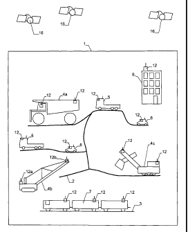
Fig. 1 schematically depicts a site 1, such
as a surface mine, to be monitored by the present system.
The figure primarily shows the components relevant in the
context of the present invention. Typically, such a site
covers a large area, in the case of a surface mine e.g.
in the range of square kilometers, with a network of
roads 2 and other traffic ways, such as rails 3. A plu-
rality of objects is present in the mine, such as:
- Large vehicles, such as haul trucks 4a,
n cranes 4b or diggers 4c. Vehicles of this type may easily
weigh several 100 tons, and they are generally difficult
to control, have very large breaking distances, and a
large number of blind spots that the driver is unable to
visually monitor without monitoring aids, such as e.g.
cameras.
- Medium sized vehicles 5, such as regular
trucks. These vehicles are easier to control, but they
still have several blind spots and require a skilled
driver.
- Small vehicles 6. Typically, vehicles of
this type weigh 3 tons or less. They comprise passenger
vehicles and small lorries.
- Trains 7.
A further type of object within the mine is
comprised of stationary obstacles, such as temporary or
permanent buildings 9, open pits, boulders, non-movable
excavators, stationary cranes, deposits, etc.
The risk of accidents in such an environment
is high. In particular, the large sized vehicles can eas-
ily collide with other vehicles, or obstacles.
For this reason, the mine 1 is equipped with
a monitoring equipment that allows to generate proximity
warnings for the personnel of the site, thereby reducing
the risk of collisions and accidents.
Basically, the each of the objects comprises
at least one first monitoring device 12 which includes a
radio based positioning system interacting with satel-
A 02796846 2012-10-18
WO 2011/130861
PCT/CH2010/000106
9
lites 16. These devices 12 communicate in wireless man-
ner, in particular by radio signals.
The first monitoring devices 12 are e.g. in-
stalled on the objects 4 - 7, and 9.
An exemplary system according to an embodi-
ment of the present invention is shown in a block diagram
in Fig. 2. The system comprises a control unit 14, such-
as a microprocessor system, which controls the operations
of the system, and in particular controls an output de-
n vice 19.
The system 15 further comprises a first moni-
toring device 15 in form of a GNSS receiver. Although it
is called a GNSS receiver in the following, it can also
be a receiver interoperating with any other radio based
positioning system for determining its position. The pre-
sent invention can be used on various types of radio
based positioning systems.
The system 15 further comprises a second
monitoring device 40. The second monitoring device 40 is
a radar device for determining the distance to a near by
object, such as within the range of e.g. 10 - 20 meters,
by means of the radio detection and ranging concept as
known to those skilled in the art.
The system 15 further comprises a radio
transceiver or circuit 17 for exchanging data with other
parts of the monitoring apparatus, e.g. with other sys-
tems 12.
A control unit 14 accesses a memory 18 that
comprises programs as well as various parameters, such as
a unique identifier of the monitoring devices 12 and 40.
The output device 19 advantageously comprises
output elements such an optical display 20 using LED's,
LCD's, etc. as well as an acoustic signal source 21, such
as a beeper. In addition, such output device 19 may com-
prise another speaker via which electronically generated
voice messages may be issued as warnings. Proximity warn-
ings can, e.g. be issued by the optical display 20 that
A 02796846 2012-10-18
WO 2011/130861
PCT/CH2010/000106
can be observed by the user and/or an acoustic signal. In
addition, the acoustic signal source 21 can generate
voice data and/or other types of sound. The control unit
14 may also be part of the output device 19. Output de-
vice 19 including output elements 20, 21 and control unit
14 in an embodiment can be arranged in a common housing.
In another embodiment, only the output elements are ar-
ranged in a common housing, and the control unit may be
located remotely. The control unit 14 may evaluate the
10 data received from the monitoring devices 12 and 40 and
may generate signals supplied to the output device 19 for
generate or triggering the warnings. In another embodi-
ment, the common output device may be embodied such that
at least one of the output elements is designed for issu-
ing both, the first and the second proximity warning.
The primary purpose of the system 15 is to
generate proximity warnings in case that there is a dan-
ger of collision. As mentioned in the introduction, this
is achieved by receiving at least positional signals
through GNSS receiver and exchanging data derived there-
from with other systems in order to calculate relative
positions and probabilities for collisions, and by re-
ceiving distance signals through the radar device. Any
data supplied by the monitoring devices in general, or
subject to specific thresholds, may be logged in a log
60. The log 60 may also be integral part of the memory
18. In the log, different data may be recorded: It may be
such that the positional data and/or the distance data
may be recorded continuously or triggered by one of the
data fulfilling a criterion such as the distance being
less than a threshold which may indicated an upcoming
crash. And/or, the signals generated by the control unit
14 for triggering the warnings may be recorded. Any log
may help in later verifying why a crash may have hap-
pened, and may verify the proper operation of the system.
In addition, in a preferred embodiment, a de-
tection device for detecting fatigue of the operator /
A 02796846 2012-10-18
WO 2011/130861
PCT/CH2010/000106
11
driver may be provided and integrated into the overall
system such that the first warning and / or the second
proximity warning may depend on a signal from such fa-
tigue detection device. In another embodiment, such fa-
tigue detection device may be in a position to issue a
separate warning itself.
The operation of the first monitoring devices
can be basically as in conventional systems of this type,
such as e.g. described in WO 2004/047047 and need not be
lo described in the very detail herein. In short, in a sim-
ple approach, each device obtains positional data derived
from a signal from GNSS receiver. This positional data
allows determining the position of the device and is
stored in a "device status dataset". The device status
n dataset also contains a unique identifier (i.e. an iden-
tifier unique to each of the first monitoring devices 12
used on the same site). The device status dataset is
emitted as a radio signal through transceiver 17. At the
same time, the device receives the corresponding signals
20 from neighboring devices and, for each such neighboring
device, it calculates the relative distance d by sub-
tracting its own coordinates from those of the neighbor-
ing device.
A proximity warning triggered by the posi-
25 tional information - which for the first monitoring de-
vice includes distance information with respect to an-
other object, too for the reason that the distance is de-
termined by differences in the position of the two ob-
jects in question - can be generated by means of various
30 algorithms. Examples of such algorithms are described in
the following. In a very simple approach, it can be
tested if the absolute value of the relative distance d
is below a given threshold. If yes, a proximity warning
will be issued. This corresponds to the assumption that a
35 circular volume in space is reserved for each object. The
radius of the circular volume attributed to an object can
e.g. be encoded in its device status dataset. A more ac-
A 02796846 2012-10-18
WO 2011/130861
PCT/CH2010/000106
12
curate algorithm can e.g. take into account not only the
relative position, but also the driving velocities and
directions of the vehicles. An improvement of the predic-
tion of collisions can be achieved by storing data in-
dicative of the size and/or shape of the vehicle that a
monitoring device is mounted to. This is especially true
for large vehicles, which may have non-negligible dimen-
sions. In a most simple embodiment, a vehicle can be mod-
eled to have the same size in all directions, thereby de-
l() fining a circle/sphere "covered" by the vehicle. If these
circles of spheres of two vehicles are predicted to in-
tersect in the near future, a proximity warning can be
issued. Instead of modeling an object or vehicle by a
simple circle or sphere, a more refined modeling and
15 therefore proximity prediction can be achieved by storing
the shape (i.e. the bounds) of the vehicle in the dataset
or by determining the same dynamically as in the embodi-
ments described below. In addition, not only the shape of
the vehicle, but also the position of the GNSS-receiver
20 (or its antenna) in respect to this shape or bounds can
be stored in memory 18.
The second monitoring device 40 - which is
not shown in Figure 1 but is assumed to be present on
many of the vehicles for monitoring the vicinity in at
25 least one direction - may issue e.g. via a control unit
for evaluating the measured distances a warning signal
which triggers the output device to issue the second
proximity warning when the distance is less than a
threshold, e.g. less than 5 meters. Subject to the meas-
30 uring principle used and the range of interest to be
scanned the maximum range within which another object can
be detected, e.g. in a runtime measurement measuring the
time between issuance of a signal, be it a radio signal,
a light signal - in particular a laser signal-, or a
35 sonic signal - in particular an ultrasonic signal -, and
the receipt of the signal reflected at the remote object,
may be preferably less than twenty meters. The advantage
A 02796846 2012-10-18
WO 2011/130861
PCT/CH2010/000106
13
of such monitoring devices is that in contrast to the
GNSS based devices the remote object needs not to be
tagged or equipped with any detection unit. This is why
such a monitoring device ideally complements the GNSS
based monitoring device. Preferably, the second monitor-
ing device is based one of radar, lidar and sonic tech-
nology for determining the distance to a near-by object.
Alternatively*, or in addition to evaluating
the distance to other objects by means of these objects
m having GNSS receivers installed, too, the corresponding
positional information of these objects being transmitted
to the present object, and a distance value being derived
from the positional information of the present and the
other object, the positional information of the present
object can also be compared to positional information of
preferably stationary objects electronically stored in a
map 50 as shown in Figure 2. The map 50 may include in-
formation on stationary objects of a site, and the con-
trol unit 14 may be designed for determining a distance
between the current position of the present object from
e.g. stationary objects derived from such map 50. The
output device 19 may be designed for issuing the first
proximity warning when such distance is less than a
threshold.
When it comes to the arrangement of the sec-
ond monitoring device(s) at an object, it is advantageous
to address each side of the object with a second monitor-
ing device. In this sense, Figure 3 illustrates a sche-
matic top view on a vehicle 6 equipped with four second
monitoring devices 40 in form of lidar devices, one lo-
cated at each side of the vehicle 6. Alternatively, the
lidar devices 40 can be located at the edges of the vehi-
cle 6. Both arrangements are beneficial for covering a
large area in the vicinity of the mobile object for prox-
imity and/or collision detection purposes.
In such arrangement, the warnings based on
information delivered by one of the second monitoring de-
A 02796846 2012-10-18
WO 2011/130861
PCT/CH2010/000106
19
vices 40 may preferably allow for an indication which one
of the several second monitoring devices 40 has detected
an object near-by resulting in the warning. Preferably,
the warnings issued by the several second monitoring de-
vices 40 can be distinguished. For example, the warning
assigned to the second monitoring devices 40 is an opti-
cal warning issued by an optical display 20 in form of
multiple LEDs (light emitting diode), as shown in Figure
4. An output device - understood as combination of sev-
io eral output elements be it visual or acoustic including
speech based warning elements - may include the optical
display 20 including four LEDs 200, 201, 202, 203 ar-
ranged in the corners of a virtual square or on a virtual
ring by this indicating a direction, for example in rela-
15 tion to a forward moving direction of the vehicle. When-
ever the radar device to the right hand side in Figure 3
causes issuing a second warning the corresponding LED 201
to the right hand side of the optical display 20 is
flashing. Whenever the radar device to the left hand in
20 Figure 3 causes issuing a second warning the correspond-
ing LED 203 is flashing, etc. By this the operator is
aware to which side of the vehicle another object is
close by. In addition to the four LEDs 200 - 203 repre-
senting warnings triggered by the second monitoring de-
25 vices 40, the first monitoring device 12 is assigned two
more rings /squares of LEDs 300 - 303 and 400-403 in the
optical display 20. Provided the first monitoring device
12 is capable for identifying other tagged objects not
only with respect to the distance but also with respect
30 to the direction, the middle ring of LEDs 300-303 is as-
signed to the first monitoring device detecting a tagged
object in the mid-range, and the outer ring of LEDs 400 -
403 may be assigned to an object detected in a far range
by the first monitoring device 12. Overall, such visual
35 warning system may comprise three LEDs per direction, two
of which are assigned / connected to the first monitoring
device 12, the last one being assigned to the second
A 02796846 2012-10-18
WO 2011/130861
PCT/CH2010/000106
monitoring device 40 such that the operator always is in
a position to determine which monitoring device 12, 40 is
issuing a warning. In addition, each ring of LEDs may
have a different colour than another ring of LEDs. For
5 example, the LEDs 200 - 203 of the inner ring may flash
in a warning colour such as red, while the LEDs 400 - 403
of the outer ring may flash in a colour different to red,
such as green, indicating that no immediate action may be
required, while the colour of the LEDs 300 - 303 in the
lo middle ring may be yellow for example, indicating medium
risk. Instead, or in addition, the LEDs may flash with
different frequencies, the higher the risk, the higher
the frequency. Instead of the LEDs, there may be provided
other visual elements, such as warning symbols, text, or
15 other signs, arranged as individual elements, or, com-
bined, on a display.
Also, the position of the first and the sec-
ond visual proximity warnings may be differently ar-
ranged, e.g. on a common flat panel display.
In general, the first and the second prox-
imity warnings are preferably different in their appear-
ance for better enabling an operator to immediately as-
sess the risk associated. This not only holds for the
warnings being embodied as visual warning. Instead the
first proximity warning may be a visual warning, whereas
the second proximity warning may include an acoustic
warning in addition to a visual warning, or an acoustic
warning exclusively. An acoustic warning may be a beep or
any other sound drawing attention to the monitoring sys-
tem. In another embodiment, it may even be that both
proximity warnings include acoustic warnings. Again, such
acoustic warnings then differ, for example, in their vol-
ume, their frequency, their beeping frequency, their
sound, etc.
According to another aspect of the present
invention, there is provided that an appearance of the
first proximity warning is variable subject to said loca-
A 02796846 2012-10-18
WO 2011/130861
PCT/CH2010/000106
16
tion/distance data. Such embodiment is already described
with respect to the above LED display. The same may apply
to an appearance of second proximity warnings which may
be variable subject to said distance data. In an optical
display such as the one above, there may be provided an-
other ring of four LEDs arranged as a very inner ring
which for example flashes at high frequency whenever an
object detected by the second monitoring device is, for
example, closer than two meters from the object holding
lo the first and the second monitoring devices 12, 40.
According to another preferred embodiment,
the second and/or first proximity warning may be modified
in its appearance subject to the positional data supplied
by said first monitoring device.
Similar to the above, said first and/or sec-
ond proximity warning can also be modified in its appear-
ance subject to said distance data supplied by said sec-
ond monitoring device.
In another embodiment, the second proximity
warning is modified in its appearance subject to previous
distance data. For example, in a scenario, where a digger
is digging close to a wall which most often is not
equipped with the first kind of a monitoring device, the
second monitoring device will cause issuance of warnings
each time the digger approaches the wall, although the
operator is already aware of this obstacle. In order not
to distract the operator by ongoing warnings, the system
may be embodied such that whenever the distance to an ob-
ject frequently appears within a certain time period, it
can safely be assumed that the operator is aware of such
obstacle such that the second warning is suppressed or
modified such that its intensity decreases with each new
approach. Such logic in particular can be combined with
the positional information received from the first moni-
toring device: Whenever the position of the digger re-
mains in about the same area and the above approach sce-
nario occurs, it can even more safely be assumed that the
A 02796846 2012-10-18
WO 2011/130861
PCT/CH2010/000106
17
obstacle is a permanent one being noticed by the operator
already.
Such concept may also apply to a modification
of the first warning, e.g. whenever a huge building is
equipped with a GNSS based receiver, and a vehicle is be-
ing run in an area close to such building, the first
proximity warning may be modified in its appearance sub-
ject to previous positional data allowing for an inter-
pretation that the vehicle currently is operating near.
and such building and the operator is aware of this.
In general, such modification of a proximity
warning may, e.g. include a complete suppression of the
warning, or, in case of an acoustic warning include one
of a decrease and an increase in at least one of the vai-
n ume and the alternating frequency and the frequency spec-
trum of said respective acoustic warning, or in case of a
visual warning include one of a decrease and an increase
in one at least one of the intensity, the color, the
flashing frequency, the representation of warning sym-
bols, the position on the output device, and the appear-
ance of said respective visual warning.
While there are shown and described presently
preferred embodiments of the invention, it is to be dis-
tinctly understood that the invention is not limited the-
reto but may be otherwise variously embodied and prac-
ticed within the scope of the following claims.