Note: Descriptions are shown in the official language in which they were submitted.
CA 02796848 2012-10-18
WO 2011/133157
PCT/US2010/032061
INSERT FOR USE WITH A ROLL OF WEB MATERIAL, AND PROVIDING A UNIQUE
IDENTIFIER FOR THE ROLL OF WEB MATERIAL
BACKGROUND OF THE INVENTION
The present invention is generally directed to product dispensers and, more
particularly, to a dispenser having a lockout feature that prevents the
dispensing of product from a
non-approved source.
Automatic towel and similar product dispensers have been developed to reduce
the
waste generally associated with manual dispensers. Automatic dispensers
typically include a motor
driven drive roller that advances web material, such as hand towel material,
from a web material roll.
Early automatic dispensers required a user to depress a feed button to
activate the drive roller. More
recently, automatic dispensers have incorporated proximity sensor technology
to allow hands-free or
otherwise contact-free activation of the drive roller.
Conventional automatic dispensers advance web material from the web material
roll
according to predetermined settings that result in the same amount of web
material being dispensed
regardless of the particular characteristics of the web material to be
dispensed. For example, a
conventional automatic towel dispenser will advance a fixed amount of web
material from a web
material roll independent of the absorbency of the web material. As a result,
it is possible for too
much or too little web material to be dispensed; both of which can lead to
waste. When too much
web material is dispensed, the excess cannot be retrieved and reused and
therefore creates waste.
When too little web material is dispensed, a user will often retrigger the
dispenser to dispense
additional web material possibly resulting in additional waste.
Accordingly, a number of "smart" dispensers have been developed that are able
to
obtain information about certain characteristics of a web material roll, or
the web material wrapped
therearound, and adjust the dispensing settings accordingly. One such
dispenser is described in U.S.
1
CA 02796848 2012-10-18
WO 2011/133157
PCT/US2010/032061
Pat. Pub. No. 2005/0171634. This publication describes a dispenser having a
reader or scanner that
communicates with an RFID "smart" chip or tag embedded in the core of a roll.
The smart chip
includes information relating to the type of product to be dispensed. For a
roll of hand towel
material, that information may include absorbency, basis weight, and
manufacturer. The scanner
reads this information from the smart chip and communicates that information
to a processor that
adjusts performance settings accordingly. For example, the feed length may be
adjusted based on
the information contained in the smart chip. Additionally, the processor may
disable the automatic
drive or feed components if an unapproved or unrecognized roll is loaded into
the dispenser. The
automatic drive components may also be disabled if no information is gathered
from the smart chip,
which may occur when a roll absent a smart chip is loaded into the dispenser.
This "lockout" feature
is intended to reduce jamming of the dispenser, damage to the dispenser,
and/or unsatisfactory
dispensing of web material that may result from use of an unapproved or an
unrecognized roll.
In addition to significantly adding to the cost of each roll and the dispenser
itself by
virtue of the necessary reader(s) and circuitry, such smart chips or RFID tags
are only effective if the
web material of the roll matches the information encoded in the smart tag. If
there is a mismatch
between the web material and the encoded information, the performance settings
of the dispenser
will not be tailored to the specifics of the web material to be dispensed.
Further, the lockout feature
is designed to prevent the use of unauthorized or unrecognized rolls with the
automatic dispenser. If
there is an inconsistency between the encoded information and the actual web
material to be
dispensed, the lockout feature may not function properly.
Another "smart" dispenser, which is described in U.S. Patent No. 7,040,566,
uses a
bar code-embedded roll and a bar code reader to determine if the roll is from
an authorized source
before the dispenser is activated to dispense material from the roll. The bar
code reader is described
as a phototransistor reflective object sensor that reads the bar code
associated with a roll loaded into
2
CA 02796848 2012-10-18
WO 2011/133157
PCT/US2010/032061
the dispenser and transmits a code signal to a controller that compares the
code signal to a set of
approved codes maintained in a computer readable database. If the code
associated with the code
signal does not match an approved code, the dispenser is automatically locked
out form dispensing
material from the loaded roll.
While such a smart dispenser is believed to be effective in preventing
unauthorized
rolls from being loaded into a dispenser, the cost and the collective size of
the components can result
in a significant increase in the overall cost, complexity, and size of the
dispenser. For example, such
a lockout system requires not only the aforementioned bar code reader/sensor
and microcontroller
but also an analog to digital converter for digitizing the analog output of
the reader.
The above-described systems can also often be circumvented by removing the bar
code or RFID tag and placing them on the core of a new roll or merely in
appropriate proximity to
the reader. The dispenser can then be loaded with an unapproved or
unrecognized roll and be caused
to operate as if an approved or recognized roll has been loaded. As a result,
the waste management,
performance and supply control advantages provided by the smart chips or RFID
tags may not be
realized.
BRIEF DESCRIPTION OF THE INVENTION
The present inventors have found that the advantages provided by smart chips,
bar
code readers, or RFID tags can be realized while avoiding the pitfalls and
costs associated therewith.
More particularly, the present invention is directed to an automatic web
material dispenser that
determines if the roll loaded into the dispenser is approved for use with the
dispenser. In one
embodiment of the present invention, in order to achieve this result, it
compares a baseline system
frequency to the frequency after the roll has been loaded into the dispenser
and determines if
changed frequency is within a predetermined range. If so, then the roll is
approved for use with the
3
CA 02796848 2012-10-18
WO 2011/133157
PCT/US2010/032061
dispenser and the dispenser is activated. In one embodiment, a plug having a
metallic feature is
loaded into, and adhesively bonded to an open end of a roll of web material.
Bonding the plug to the
roll is intended to discourage removal of the plug from the roll and inserting
the plug into an
otherwise plug-less roll of web material. It is also contemplated that the
plug could be press-fit into
the open end of the roll and in a manner that would discourage removal of the
plug from the roll, i.e.,
results in damage to the plug and/or roll if the plug was removed. When the
appropriate modified
frequency is recognized, the system can be set to adjust for various
particulars of the web material to
be dispensed, such as brand name, type, size, and the like, that can be used
to automatically tailor the
performance settings of the dispenser.
It is therefore one object of the present invention to provide an automatic
product
dispenser having a lockout feature that cannot be easily circumvented.
It is a further object of the invention to provide a roll having a recognition
device or
material that cannot be transferred to other rolls.
Therefore, in accordance with one aspect of the present invention, an
apparatus for
dispensing product from a roll is disclosed. The apparatus includes a drive
roller adapted to advance
product from a roll. The roll to be loaded into the dispenser includes a
frequency changing device or
material that may be indicative of the product carried by the roll or merely
the source or provider of
the roll. The apparatus further includes a controller associated with the
drive roller and adapted to
determine the frequency resulting from the presence of the frequency changing
device or material of
the roll, compare the system base frequency to the changed frequency and then,
if the changed
frequency matches a predetermined frequency, falls within a predetermined
range, or is changed a
predetermined amount or percentage, permit the drive roller to advance the
product from the roll. If
the changed frequency does not match the predetermined frequency, shift or
range, then the drive
4
CA 02796848 2014-12-11
motor will not be actuated, thereby preventing the dispensing system from
operating to advance
product from the roll.
In accordance with another aspect, the present invention includes a method of
regulating product dispensing from a dispenser. The method includes
determining if a roll
includes a frequency shifting device or material that fits the predetermined
profile. If it does,
then the dispensing particulars of the roll can be known and/or set.
According to another aspect, the present invention includes a plug for
insertion
into an open end of a roll of web material for use with an automatic
dispensing device. The
plug has a metallic feature operative as a frequency shifting device for
identifying a brand or
source of the roll associated therewith.
Other objects, features, and advantages of the invention will become apparent
to
those skilled in the art from the following detailed description and
accompanying drawings. It
should be understood, however, that the detailed description and specific
examples, while
indicating preferred embodiments of the present invention, are given by way of
illustration and
not of limitation. The scope of the claims should not be limited by particular
embodiments set
forth herein, but should be construed in a manner consistent with the
specification as a whole.
BRIEF DESCRIPTION OF THE DRAWINGS
Preferred exemplary embodiments of the invention are illustrated in the
accompanying drawings in which like reference numerals represent like parts
throughout.
In the drawings:
FIG. 1 is an isometric view of an automatic towel dispenser;
FIG. 2 is a front elevation view of the automatic towel dispenser of FIG. 1
with
the front cover removed;
5
CA 02796848 2012-10-18
WO 2011/133157
PCT/US2010/032061
FIG. 3 is an isometric view of a roll carrier assembly for use with the
automatic towel
dispenser of FIGS. 1-2;
FIG. 4 is front elevation view of the roll carrier assembly shown in FIG. 3;
FIG. 5 is a section view of a portion of the roll carrier assembly shown in
FIGS. 3 and
4;
FIG. 6 is section view of a hub assembly according to another embodiment of
the
invention;
FIG. 7 is an exploded view of that shown in FIG. 6;
FIG. 8 is an isometric view of a plug according to another embodiment of the
invention and used to connect a roll web material to the hub assembly of FIGS.
6 and 7;
FIG. 9 is a section view of the plug of FIG. 8;
FIG. 9A shows placement of a conductive ring at various positions within the
plug of
FIG. 8;
FIG. 10 is a section view of a plug according to another embodiment of the
invention;
FIG. 11 is a top plan view of the plug of FIG. 10;
FIG. 12 is a schematic view of a control circuit associated with the product
discriminating assembly; and
FIG. 13 is a perspective view of paper towel core according to another
embodiment
of the present invention.
6
CA 02796848 2012-10-18
WO 2011/133157
PCT/US2010/032061
DETAILED DESCRIPTION OF THE INVENTION
The present invention will be described with respect to an automatic towel
dispenser
for dispensing web material, but it is recognized that the invention is
applicable to automatic
dispensers adapted to automatically dispense other types of products,
including other paper and non-
paper products. Additionally, the invention is applicable with touch-based and
touchless automatic
dispensers, such as those commercially available from The Colman Group, Inc.
of Elkhorn,
Wisconsin.
As will be explained in greater detail further below, the present invention is
generally
directed to a dispenser, such as a paper towel dispenser, that includes
circuitry for generating an
electromagnetic field generally around a roll mount. When an authorized roll
is mounted onto the
roll mount, the roll will cause a change in the frequency of the
electromagnetic field. More
particularly, the circuitry includes a frequency generator (oscillator) and a
coil for creating the
electromagnetic field and the roll includes a uniquely constructed closed
loop. Thus, when the roll is
loaded into the dispenser, the frequency generator will generate a new
waveform having a changed
frequency reflective of the mutual inductance between the coil and the closed
loop. The new
waveform, or one or more characteristics thereof, are the result of the
properties of the closed loop.
The new waveform, or some form thereof, may then be analyzed to determine if
the roll loaded into
the dispenser is authorized for use with the dispenser. If so, the dispenser
will dispense material
from the roll. If not, the dispenser will be locked out and will not operate
thereby preventing
unintended or impermissible use of the dispenser.
An exemplary paper towel dispenser is shown in FIG. 1. Automatic towel
dispenser
10 includes a back cover 12 designed to be wall-mounted and a front cover 14
coupled to the back
cover 12 by a hinge 16. Paper towel or web material is fed from a web material
roll (not shown)
contained within the automatic towel dispenser 10 through dispensing slot 18
by a drive assembly
7
CA 02796848 2014-12-11
20, shown in FIG. 2. The clamshell design of the automatic towel dispenser 10
allows a roll to
be loaded into the automatic towel dispenser 10 by unlocking the front cover
14 from the back
cover 12 in a known manner and then rotating the front cover 14 downwardly
about hinge 16.
As shown in FIG. 2, drive assembly 20 is mounted to the back cover 12 and
includes a PC board and motor contained within housing 22 and operatively
associated, in a
known manner, with a drive roller assembly 24. The drive roller assembly 24 is
designed to
grab and forcibly advance web material from a roll of web material (not shown)
through
dispensing slot 18. The drive roller assembly 24 may be of conventional
design, such as that
described in U.S. Pat. No. 7,168,653. As will be described in greater detail
below, the motor
may be controlled by a processor adapted to smartly control operation of the
motor and drive
roller assembly, including, when appropriate, disablement of the motor so as
to lock out its
functionality when an unapproved roll is loaded into the automatic towel
dispenser 10.
In one embodiment of the present invention, a continuous sheet of web material
is advanced from a roll (not shown) that is preferably mounted on a carrier
assembly 26 of the
type that includes a pair of roll support plates 28, 30 that carry a guide
wire 32, as shown
further in FIGS. 3-4. Each support plate 28, 30 has an inwardly facing hub 34,
36, respectively,
that is designed to extend partially through the hollow core of the roll. The
hubs 34, 36 have a
generally circular cross-section to match that of a plug that is inserted into
the hollow core of
the roll. As will be described more fully below, the plug provides two
generally functions. It is
used to mount the roll in the dispenser, and more particularly to hub 34, and
includes a metallic
member that modifies the waveform emitted by a coil contained in hub 34. As
further shown in
FIG. 2, a wire 38 extends from the hub 34 to an oscillator within housing 22.
As will be
explained, the oscillator and a coil create an electromagnetic field generally
about the hub 34.
8
CA 02796848 2012-10-18
WO 2011/133157
PCT/US2010/032061
Referring to FIG. 5, the hub 34 provides a housing for a bobbin 40 around
which a
coil (wire winding) 44 may be wrapped. When the coil 44 is energized, an
electromagnetic field is
,
generated. As noted above, the hub 34 is received by one end of the hollow
core 46 of the roll. The
core 46 has an inner surface 48 and an outer surface 50. The outer surface 50
is impregnated or
otherwise carries a continuous ring of conductive material 52. Alternately,
the conductive material
52 could be placed on the inner surface 48, or both the inner and outer
surfaces 48, 50, or
impregnated in the core material. In the illustrated embodiment, the
conductive material 52 is
arranged in the form of a ring that envelopes a portion of the outer surface
50 of the core 46. The
conductive ring of material 52 (or alternatively, a closed circuit (not shown)
or other type of closed
loop) is designed to modify the base system frequency as it interacts with the
electromagnetic field
of the coil. For example, the conductive material 52 for a given core may
include one or more of
copper, gold, nickel and silver. The width, thickness, purity, type and
location of the conductive
material can affect the degree of frequency shift or change. In one
embodiment, the amount of
frequency changing device or material can be used to identify the brand of the
roll.
In one embodiment, the closed loop 52 is formed as a ring of conductive
material
around a portion of a roll core 46. It is recognized, however, that in
alternate embodiments, the
closed loop 52 may be arranged in other patterns to uniquely identify the
roll. For example, multiple
rings of conductive material 52 could be used. In one embodiment, one type of
conductive material
52 is used, but it is recognized that mixtures of various types of conductive
material 52 could be
used. Regardless of the contents of the conductive material 52 and how it is
placed on the roll, the
resulting frequency can uniquely identify the brand, source, or some other
defining characteristic of
the roll so that a determination can be made as to whether the roll may be
used with the automatic
towel dispenser 10. The resulting frequency may also identify the type of
material, the size of the
9
CA 02796848 2012-10-18
WO 2011/133157
PCT/US2010/032061
roll, and other parameters that may be useful in establishing operating
parameters for the automatic
towel dispenser 10.
FIGS. 6 and 7 show a hub assembly 54 according to another embodiment of the
invention. Hub assembly 54 includes a support plate 56 to which a bobbin 58 is
affixed in a known
manner. A coil winding 60 is mounted to the bobbin 58, and a cover 62 having
an opening 64 fits
over the bobbin 58 and thus coil 60. An end cap 66 snaps into or is otherwise
retained by the bobbin
58. The end cap 66 fits within the hollow core of the roll. In one embodiment,
the shape of the end
cap 66 and the core of the roll are matched such that rolls having cores with
non-complementary
shapes cannot be used with the dispenser.
In another embodiment of the invention, a conductive member is loaded into a
plug
that is used to mount a roll of web material to the hub. As shown in FIG. 8,
plug 68 is similar in
outward appearance to the end cap 66 shown in FIGS. 6 and 7. More
particularly, the plug 68 has a
generally cylindrical shaped stem 70 and a rounded cap 72 preferably
integrally formed with the
stem 70. In one embodiment, the stem 70 is shaped to be complimentary with the
opening formed in
the bobbin 58. In this embodiment, the complimentary engagement surfaces of
the stem 70 and the
bobbin 58 prevent the stem from being loaded improperly into the bobbin or
used with an unmatched
bobbin. An annular ridge 74 is formed with the cap 72 and provides a seat for
the roll of web
material when the roll is loaded onto the plug 68. Spaced from the ridge 74
are a set of radial edges
76 that are used to "grip" the core of the roll.
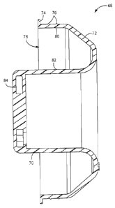
As shown in FIG. 9, the stem 70 and the cap 72 are formed as a single unitary
structure so that an annular recess 78 is provided between the inner surface
80 of the cap 72 and the
outer surface 82 of the stem 70. This construction allows the plug 68 to be
inserted into the opening
in the bobbin 58 in a manner that seats the stem 70 within the core of the
coil winding 60. In the
embodiments of the invention described above, conductive material was
incorporated into the roll of
CA 02796848 2012-10-18
WO 2011/133157
PCT/US2010/032061
web material, such as a conductive ring formed with the roll core. In this
alternate embodiment, the
plug 68 contains conductive material that interacts with the electromagnetic
field generated by the
coil 44 to provide a "handshaking" between the dispenser and the roll of web
material. While
inclusion of the conductive material in the plug 68 may take many forms, such
as embedded pieces
of conductive material randomly displaced throughout the stem and/or cap, in
one embodiment, a
metallic ring 84 is loaded into the stem 70. In a low cost version of the
present invention, the
metallic ring 84 is a simple metal washer. In a preferred embodiment, the
metallic ring 84 is insert
molded with the stem 70 and cap 72. As shown in FIG. 9A, for example, the
metallic ring 84 can be
molded, or otherwise positioned, at one of multiple positions within the stem
70 to define the
inductive signature of the plug. It will be appreciated that in addition to
position, the type of metal
and the mass of the metal will impact how the ring 84 interacts with the
electromagnetic field
generated by the coil 44. In this regard, it is understood that the position
of the ring 84, its size, and
its material composition may be selected to provide a unique signature or
marker for the plug 68 and
thus the roll associated with the plug 68. It will also be appreciated that a
plug may have more than
one conductive insert, e.g., metallic ring, to define its inductive signature.
Further, it will be
appreciated that the conductive element may take a different shape or form
than that illustrated
herein. For example, the stem may include recesses that are loaded with
conductive rods or pins to
define the inductive signature for the plug.
In the embodiment shown in FIG. 9, the metallic ring 84 is insert molded with
the
plug 68 and thus is encased within the plug 68. Integrally forming the ring 84
with the plug 68 locks
the "identity" of the plug and prevents the ring 84 from being removed from
the plug without
destroying the plug itself. Preferably, the plug and the bobbin (or some other
element of the hub
assembly) are color coded so that the plug and hub assembly are matched to one
another.
11
CA 02796848 2012-10-18
WO 2011/133157
PCT/US2010/032061
Another embodiment of the invention is shown in FIGS. 10 and 11. Plug 112 has
a
stem 114 and a head 116. The stem 114 has a generally hollow interior defined
by an annular
surface 118. The interior surface 118 is stepped that allows a keyed plastic
insert 120 encasing a
conductive element (not shown) to be drop-set at different depths within the
stem 114. In a preferred
embodiment, four different sets of keyways 122, 124, 126, 128 are formed along
the interior surface
118 of the stem 114 and radially spaced from one another to define four
different depths at which the
plastic insert 120 may be positioned. Each set of keyways preferably includes
three keyways to
match the three keys 130 formed along an outer radial edge of the plastic
insert 120. In one
embodiment, the plastic insert 120 is sonic welded or otherwise fixed in place
after the plastic insert
120 is set to the desired depth so that the position of the insert 120 cannot
be altered. For example,
the insert 120 could be snap-fit into place within the stem 114.
As referenced above, and illustrated in FIG. 9A, the position of the plastic
insert 120
could be changed to modify the effect the metallic member contained within the
insert 120 has on
the electromagnetic field emitted by the coil. For example, in combination
with the conductive
properties of the conductive member, each depth setting could be used to
tailor certain operating
parameters of the drive roller assembly, such as advancement length. This
would allow the
advancement length to be set for a given roll by changing the position of the
insert within the stem of
the plug. In yet a further embodiment, the plastic insert and the bobbin (or
exposed article of the hub
assembly) are color coded. Color coding these components provides a visual
reminder to an installer
that the insert 120 for the plug must correspond to the color of the bobbin to
ensure proper operation
when the plug, and roll, are loaded.
Additionally, it will be appreciated that the plug could be secured or coupled
to the
roll in a number of ways. For example, the plug could be adhesively bonded to
an open end of a roll
of web material. Bonding the plug to the roll is intended to discourage
removal of the plug from the
12
CA 02796848 2012-10-18
WO 2011/133157
PCT/US2010/032061
roll and inserting the plug into an otherwise plug-less roll of web material.
In a similar manner, the
plug could be press-fit into the open end of the roll and in a manner that
would discourage removal
of the plug from the roll, i.e., results in damage to the plug and/or roll if
the plug was removed.
As shown in FIG. 12, the system of the present invention includes a control
logic
circuit 132 which includes an oscillator 134 which together with coil 44
generates an
electromagnetic field proximate the coil 44 and thus a roll positioned over
the hub 34. The oscillator
134 and the coil 44 generate the electromagnetic field at a predetermined
frequency which
establishes a base system frequency. When a roll having an inductive element,
e.g., a ring of
conductive material or a plug having a conductive element, associated
therewith is brought into
proximity of coil 44, preferably by mounting the roll on the hub 34, the
mutual inductance between
the coil 44 and the inductive element will cause the oscillator to generate a
waveform of a different
frequency than that of the base system frequency. The output of the
oscillator, i.e., waveform, is
input to a frequency sampler 136 (e.g., an op-amp, logic gate, comparator,
etc.) which effectively
determines the frequency of the new waveform generated by the oscillator. The
frequency, in effect,
is representative of the mutual inductance generated by placement of the roll
onto the hub or
insertion of the plug into the bobbin. A microprocessor 138 analyzes the
output of the comparator
and, more particularly, compares the frequency, or some characteristic value
thereof, to a reference
value 140. The reference value corresponds to a value indicative of an
authorized roll. In this
regard, the microprocessor 138 includes, or access memory, containing one or
more reference values
representative of various authorized roll types, brands, etc.
It will be appreciated that the aforementioned comparison can take many forms.
For
example, the comparison can be done by measuring the percent of change of the
mutual inductance
relative to the system frequency, i.e., output of the oscillator before the
roll is placed on or proximate
the hub. If the comparison yields a match against the reference, the control
logic circuit energizes
13
CA 02796848 2012-10-18
WO 2011/133157
PCT/US2010/032061
the system enabling the drive motor to drive the drive roller and dispense web
material, as indicated
by block 142. If there is no match, the system is not energized and no
material can be dispensed, as
represented by block 144. The automatic towel dispenser 10 may include an
indicator LED, for
example that is illuminated when the lockout feature is activated.
If an unauthorized roll core or plug is loaded on the carrier assembly, the
measured
frequency or other value will not match the reference frequency or value thus
indicating that an
unauthorized roll or plug has been loaded on the carrier. It is recognized
that the web material
dispenser 10 may be adapted to drive multiple types of rolls. Thus, in one
preferred embodiment,
the automatic dispenser includes a database that is loaded with multiple
reference frequencies or
values. It is further contemplated that suitable diagnostic tools may be used
to provide in-field
updates to the database.
A number of embodiments are contemplated for providing the closed loop on or
in
association with the roll of web material in order to provide a means to cause
a frequency change in
accordance with the present invention. In a first embodiment, a roll core is
coated or impregnated
with at least one ring of conductive material. The core can be coated on the
inside, on the outside or
have the conductive material impregnated somewhere between the inside and
outside of the core. In
a second embodiment, an insert is provided which can be removed or permanently
placed inside the
core. The insert can be in the form of a plastic or paperboard plug that
includes a ring of conductive
material or other closed loop. In a third embodiment a label in the form of a
ring impregnated with
conductive material can be affixed to the side of the roll of web material. In
a fourth embodiment,
the web material itself can be coated or impregnated with conductive material
to form a ring giving
the appearance of, for example, a colored stripe used to indicate the end of a
roll of register tape. In
the fifth embodiment, a removable paper or other band coated or impregnated
with a conductive
material that encircles the roll of web material at the time of mounting of
the web material in the
14
CA 02796848 2014-12-11
dispenser could be used. In such case, the band would be removed prior to
threading the
dispenser for feeding the dispenser, but after the activation of the dispenser
had occurred. In
this embodiment, upon activation, the dispenser would preferably be set up to
dispense an
amount of a paper commensurate with that on the roll, prior to reactivation.
In yet a further embodiment, and with reference to FIG. 13, a web material
roll
146 has a core 148 that is partially treated with conductive material, such as
ring 150. Glue or
similar adhesive 152 is then used to secure the tail 154 of web material to
the exterior surface
of the core 148. The adhesive 154 is applied so as to overlay the ring 150 of
conductive
material. This allows the conductive ring 150 to be damaged when the tail 154
of web towel
material is pulled from the core 148. Thus, the frequency altering effect of
the core will no
longer result in match with the reference frequency or value. This prevents
the core from being
re-loaded with web material not designed to be dispensed by the dispenser. In
one preferred
embodiment, the ring 150 includes conductive material that is applied as paint
to the outer
surface of the core 148. Alternately, the conductive material could be
sprayed, rolled, or
stamped on the core. Also, electro-static techniques could be used to apply
the conductive
material. In yet another example, the core could be dipped in conductive paint
or other fluid or
even impregnated in the adhesive used to attach to roll tail.
Additionally, while the invention has been described with respect to a web
material dispenser that advances a continuous sheet of paper towel from a
roll, it is
contemplated that the present invention may be used with web dispensers that
dispense other
types of paper products, such as toilet paper, and tissue papers. Coreless
rolls and dispensers
without support hubs may be used with the present invention. Further, the
present invention
may be used with non-paper dispensers.
The scope of the claims should not be limited by particular embodiments set
forth herein, but should be construed in a manner consistent with the
specification as a whole.