Note: Descriptions are shown in the official language in which they were submitted.
CA 02796904 2012-10-18
WO 2011/133835 PCT/US2011/033528
1
ELECTROLYZING SYSTEM
BACKGROUND OF THE INVENTION
[0001] Systems are known that electrolyze water containing alkali salts to
produce acidic
electrolyzed water and alkaline electrolyzed water. Acidic electrolyzed water,
which
typically has a pH between about 2.0 and about 3.5, is a strong sterilizing
agent that is
increasingly used in a variety of sanitizing applications including in the
medical, agricultural
and food processing industries and in other institutional environments. The
alkaline or basic
electrolyzed water also has a sterilizing as well as a detergent effect and is
useful in cleaning
oil and grease stains. Sodium chloride is commonly used as the alkali salt
that is dissolved in
the water because it produces acids and bases that are environmentally
friendly, potent and
low in cost.
[0002] Commercially available water electrolyzing systems have a number of
drawbacks.
One such system has only a single ion membrane that separates the brine from
the
electrolyzed water. Such systems tend to have high levels of salt in the
acidic solution which
can lead to scale buildup and reduce the shelf life of the acidic solution.
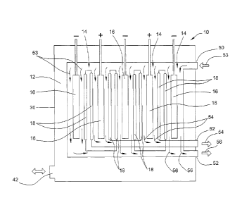
Another system is
membrane-less and depends on removing the acidic and alkaline solutions at
precise
geometric points along the flow of the brine.
[0003] Yet another system uses a three chamber structure including an anode
chamber, a
cathode chamber and an intermediate chamber arranged between the anode and
cathode
chambers. The intermediate chamber is separated on each side from the anode
and cathode
chambers by an electrode plate, a membrane and a rigid plate construction.
Each of the
electrode plates has a plurality of openings therein to allow positive or
negative ions to pass
into the anode and cathode chambers respectively. Each of the rigid plates has
striped
depressions and projections along with a number of openings to channel the
water in the
intermediate chamber to the areas of the openings in the electrode plates.
[0004] While the three chamber structure effectively minimizes salt in the
acidic output,
this system has a complex structure of rigid guide plates that can impede the
free flow of ions
into the anode and cathode chambers limiting the efficiency of the system. The
openings in
the electrodes also has an adverse effect on the consistency of the electric
fields further
hampering the efficiency of the system.
CA 02796904 2012-10-18
WO 2011/133835 PCT/US2011/033528
2
BRIEF DESCRIPTION OF THE SEVERAL VIEWS OF THE DRAWINGS
[0005] FIG. 1 is a schematic drawing of an exemplary electrolyzing system
according to
the present invention.
[0006] FIG. 2 is a schematic drawing of a more specific exemplary embodiment
of an
electrolyzing system according to the present invention.
[0007] FIG. 3 is an exploded view of the electrolytic cells of the
electrolyzing system of
FIG. 2.
[0008] FIG. 4 is another exploded view of the electrolytic cells of the
electrolyzing
system of FIG. 2.
[0009] FIG. 5 is a side view of an alternative embodiment of an electrolyzing
system.
[0010] FIG. 6 is a side sectional view of the electrolyzing system of FIG. 5.
[0011] FIG. 7 is cross-sectional view of the electrolyzing system of FIG. 5
taken along
the line 7-7 in FIG. 5.
[0012] FIG. 8 is an enlarged detail view of ends of the electrolytic cells of
the
embodiment of FIG. 5 at the fresh water inlet side of the system.
[0013] FIG. 9 is an enlarged detail view of the ends of the electrolytic cells
of the
embodiment of FIG. 5 at the finished chemical product outlet side of the
system.
[0014] FIG. 10 is an enlarged detail view of electrolytic cells of the
embodiment of FIG.
5.
[0015] FIG. 11 is a partially cutaway side perspective view showing the brine
flow
through the electrolyzing system of FIG. 5.
[0016] FIG. 12 is a partially cutaway end perspective view showing the brine
flow
through the electrolyzing system of FIG. 5.
[0017] FIG. 13 is a partially cutaway end perspective view showing the water
and
chemical product flow through the electrolyzing system of FIG. 5.
[0018] FIG. 14 is a partially cutaway end perspective view showing the
chemical product
flow out of the electrolyzing system of FIG. 5.
[0019] FIG. 15 is an exploded perspective view of another alternative
embodiment of an
electrolyzing system.
[0020] FIG. 16 is a side sectional view of the electrolyzing system of FIG. 15
showing
the brine flow passages.
[0021] FIG. 17 is a side sectional view of the electrolyzing system of FIG. 15
showing
the water and chemical flow passages between the membrane and the electrode
plate.
CA 02796904 2012-10-18
WO 2011/133835 PCT/US2011/033528
3
[0022] FIG. 18 is a lateral section view of the electrolyzing system of FIG.
15 showing
the electrolytic cells of the electrolyzing system of FIG. 15.
[0023] FIG. 19 is a partially cutaway sectional view showing the flow of
brine, water and
chemical product through the electrolyzing system of FIG. 15.
[0024] FIG. 20 is a partially cutaway sectional view showing the flow of
brine, water and
chemical product through the electrolyzing system of FIG. 15.
DETAILED DESCRIPTION OF THE INVENTION
[0025] Referring now to FIG. 1 of the drawings, there is shown an illustrative
embodiment of an electrolyzing system 10 constructed in accordance with the
teachings of
the present invention. The illustrated electrolyzing system 10 is operable to
electrolyze a
solution of water and an alkali salt to produce acidic electrolyzed water
and/or alkaline or
base electrolyzed water. Both acidic electrolyzed water (acid sanitizer) and
alkaline
electrolyzed water (base cleaner) have beneficial sterilizing and cleansing
properties making
them useful in a variety of applications including medical, agricultural, food
processing and
institutional. According to one embodiment, the water and salt solution is a
saline or brine
solution comprising water and NaCl. Electrolysis of a brine solution produces
hypochlorous
acid as the acid sanitizer and sodium hydroxide as the base cleaner. As will
be appreciated
by those skilled in the art, the present invention is not limited to
electrolysis of any particular
solution or use in any particular application.
[0026] In accordance with an important aspect of the present invention, the
electrolyzing
system 10 incorporates an open brine bath 12 into which one or more
electrolyzer cells 14 are
immersed with substantially all sides of the cells open to the brine. The use
of an open brine
bath 12 with immersed electrolyzer cells 14 eliminates the need for any
obstructive
intermediate chamber thereby allowing fluid to flow more freely through the
system. It also
eliminates the need for complex guides to direct the flow of fluid thereby
simplifying the
design as well as increasing its efficiency. In the schematic drawing of FIG.
1, the brine bath
12 includes two cells 14 one incorporating a positively charge electrode plate
16 and one
incorporating a negatively charged electrode plate 16. The cells 14 are
configured to
electrolyze the brine in the bath 12 and thereby draw in positively and
negatively charged
ions into the respective cells 14. To this end, ion permeable membranes 18 are
provided on
each side of the electrode plate 16 in each cell 14. Arranging membranes 18 on
either side of
CA 02796904 2012-10-18
WO 2011/133835 PCT/US2011/033528
4
each plate 16 increases the production achievable with each plate 16 by
allowing ions to be
drawn into the cell 14 from either side of the electrode plate.
[0027] To allow for the flow of ions towards the electrode plate 16, the
membranes 18
are ion permeable. In particular, positive ion exchange membranes 18 are
provided for
negatively charged electrodes 16 and negative ion exchange membranes 18 are
provided for
positively charged electrodes 16. The membranes 18 are configured to permit
ions to pass
therethrough but not the salt or the water. As is understood by those skilled
in the art,
minimizing the amount of salt in particularly the acidic electrolyzed water,
e.g., hypochlorous
acid, extends the shelf life of the resultant acid sanitizer product and
reduces equipment
damage due to corrosion. According to one preferred embodiment, the membranes
18 are
double sided and have a rigid yet porous structure between them.
[0028] To ensure a uniform and optimal electric field intensity, the electrode
plate 16 in
each cell 14 can have a solid construction. The use of a solid construction is
made possible
by the open bath 12 with the immersed electrolytic cell 14 configuration. Some
commercially available electrolyzing systems that utilize electrode plates
with a plurality of
openings therein to permit the passage of ions. Those openings, however, can
produce dead
zones in the electric field produced by the electrode. The design of the
system of the present
invention allows for the use of solid electrode plates 16 that do not have any
openings
therein. As a result, the electric fields produced by the electrode plates 16
are more uniform
and consistent thereby allowing the system to operate more efficiently.
[0029] A simplified system 10 according to the invention is shown
schematically in FIG.
1. In the system of FIG. 1, a brine supply 20 is provided that is connected to
the bath 12 via a
brine supply line 22. A brine recirculation line 24 is also provided which
draws spent brine
out of the bath 12 and returns it to the brine supply 20. As a result of this
arrangement, brine
is circulated through the bath 12 and around and past the electrolytic cells
14. As the brine
passes the electrolytic cells 14, it is subject to an electrolysis reaction
with the negatively
charged ions being drawn into the cell 14 with the positively charged
electrode plate 16 and
the positively charged ions being drawn in the cell with the negatively
charged electrode plate
16. Each of the electrolytic cells 14 has a fresh water inlet end 26 that is
connected to a
supply of fresh water that is directed into the interior space in the cell 14
between the
membranes 18 and the electrode plate 16. In the cell 14, the fresh water mixes
with the ions
drawn into the cell to form either the acid sanitizer (in the cell 14 with the
positively charged
plate 16) or the base cleaner (in the cell 14 with the negatively charged
plate 16). Each cell
CA 02796904 2012-10-18
WO 2011/133835 PCT/US2011/033528
14 has a chemical outlet end 28 that is connected to a line for drawing the
chemicals (acid
sanitizer or base cleaner) out of the cell 14. The flow of the brine, fresh
water and finished
chemicals through the system can be controlled by appropriate pumps.
[0030] To enable the system to be easily scaled to a desired production rate
of acid
sanitizer and/or base cleaner, the electrolytic cells 14 can have a modular
design with each
cell comprising a separate self-contained cartridge that permits multiple
cells to be assembled
together. This permits the system to be scaled to the desired production rate
simply by
adding or subtracting additional cells or cartridges. An illustrative
embodiment of a system
including such modular cells 14 is shown in FIGS. 2-4. As shown in the
schematic diagram
of FIG. 2, the illustrated embodiment includes a total of five electrolytic
cells 14 (three
negatively charged and two positively charged) arranged in a manifold type
arrangement in a
brine bath 12. The cells 14 are generally rectangular in shape and are
received in a
rectangular housing 30 that defines the brine bath 12. As shown in FIG. 2, the
illustrated
embodiment includes five cells 14, however, it will be understood that the
more or less cells
could be provided. For example, a system with only three cells could be
provided that had
either a 2:1 acid sanitizer to base cleaner production rate or a 2:1 base to
acid production rate.
Typically, adjacent cells 14 would have one positively charged electrode plate
16 and one
negatively charged electrode plate 16, so that during operation, the
positively charged ions
would flow through the membrane 18 of one cell 14 toward the negatively
charged plate 16
and the negatively charged ions would flow through the membrane 18 of the
adjacent cell 14
toward the positively charged plate 16. While the assembly of several cells 14
into a
manifold type arrangement is shown, it will be appreciated that the cells
could be
independently submerged in the brine bath 12 as each of the individual cells
is designed to be
self-contained.
[0031] The illustrated brine bath 12 includes a brine inlet/outlet 42 at the
lower end of the
bath housing 30 through which brine can be introduced into and drawn out of
the bath 12.
The bath housing 30 further includes a fresh water inlet 50, in this case,
near the upper end of
the housing that can be in communication with a fresh water supply. The
inletting fresh
water is shown by the arrow 53 in FIG. 2. As described in greater detail
below, the fresh
water introduced through the fresh water inlet 50 is directed into the
individual electrolytic
cells 14 wherein it mixes with the positively and negatively charged ions
drawn through the
membranes 18 to form the acid sanitizer and base cleaner. The bath housing 30
further
includes outlets 52 for the formed chemicals arranged in the illustrated
embodiment at the
CA 02796904 2012-10-18
WO 2011/133835 PCT/US2011/033528
6
lower end of the bath housing. The outletting acid sanitizer is referenced
with the arrow 56
and the outletting base cleaner is reference with the arrow 54 in FIG. 2. In
this case, the
water/chemicals flow downward from the top of the cells 14 and exit at the
bottom of the
cells 14. The flow of water/chemicals through the interior of the cells 14 is
shown
diagrammatically with arrows in FIG. 2 with the flow of the water being shown
with arrows
53, the flow of the base cleaner being shown with arrows 54 and the flow of
the acid sanitizer
being shown with arrows 56.
[0032] Referring to FIGS. 3 and 4 of the drawings, a pair of exploded views
are provided
which show the construction of the electrolytic cells 14 shown in FIG. 2. In
FIGS. 3 and 4,
two of the cells 14 in the middle of the manifold are shown unexploded while
the other three
have been exploded to better show the components of each cell. In this case,
each cell 14
includes an electrode plate 16 that is either positively or negatively
charged. To this end,
each electrode plate 16 has an attached lead 80 that can be connected to a
suitable electrical
supply. While the electrode plates 16 can have a solid construction as
discussed above, the
electrodes 16 could also employ a honeycomb-like structure featuring a
plurality of openings
in the electrode as well as a non-flat, such as a dimpled, configuration. Such
a construction
can have the advantage that it disrupts and introduces turbulence into the
flow of fresh water
as it passes over the electrode 16. It is thought that this additional
turbulence may help the
efficiency of the system.
[0033] In the illustrated embodiment, the three cells 14 in the middle of the
manifold
each have an ion exchange membrane 18 on either side of the electrode 16. The
two outmost
cells 14 each have only one membrane 18 with a blank wall 81 being provided on
the other
side of the cell 14 to define the edge of the cell manifold. To ensure
adequate spacing is
provided between the adjacent cells 14 as well as to support the membranes 18,
membrane
supports 38 can be provided on the outer surface of each of the membranes 18.
These
membrane supports 38 enable each cell 14 to be arranged together with an
immediately
adjacent similarly constructed cell 14 to create the manifold type arrangement
of two or more
cells. The illustrated membrane supports 38 have a window-like configuration
with six large
openings through which the brine can access the membrane 18. In this
embodiment,
cylindrical outer spacers 82 (see FIG. 4) are arranged on an outer face of
every other
membrane support 38 in the manifold and engage the outer face of the membrane
support 38
of the adjacent cell 14 so as to create space between the adjacent cells 14
into which the brine
can permeate.
CA 02796904 2012-10-18
WO 2011/133835 PCT/US2011/033528
7
[0034] To facilitate the attachment of the membranes 18 to the electrode
plates 16 and to
ensure adequate spacing between the membranes 18 and the electrode plate 16,
each cell 14
further includes a cartridge housing 40 which provides a structure to which
the electrode 16,
membrane 18 and membrane supports 38 can be attached. The cartridge housings
40 have a
generally window like configuration and are constructed in such a manner that
when the
membranes 18 and electrode 16 are connected thereto sufficient space is
provided between
the electrode 16 and the membrane 18 to permit the flow of freshwater through
the cell 14
and into which ions can be drawn to produce the base cleaner and acid
sanitizer. The interior
space in the cells 14 between the membranes 18 and the electrode plates 16
into which the
charged ions are drawn are sealed off from the brine bath 12 such that the
only flow path
from the bath 12 into the interior spaces is through the membranes. The
illustrated
configuration of the cartridge housings 40 limits the points of contact
between the cartridge
housings 40 and the electrode 16 and the cartridge housings 40 and the
respective membrane
18 and thereby defines open spaces in the area between membranes 18 and the
electrode plate
16. Advantageously, the membranes 18 are largely unobstructed by the cartridge
housings 40
and the membrane supports 38 and the membranes 18 are not directly attached to
the
electrode plates 16 so as to allow maximum ion transfer from the brine bath 12
to the cell 14.
As described further below, the lack of obstructions to the membranes 18 also
allows for fluid
to be constantly refreshed at the membrane surfaces helping to further
increase the efficiency
of the system 10. As will be appreciated by those skilled in the art, other
types of
arrangements could be used to provide the spacing between the membranes and
the surfaces
of the electrode plates. For example, raised dimples could be provided on the
electrode plate
or polyurethane standoffs could be provided.
[0035] To facilitate the flow of water/chemicals through the cells 14, each
cell includes a
fresh water distribution channel 62, in this case, through an upper edge of
the cartridge
housing 40. The fresh water distribution channel 62 communicates with the
space between
the electrode 16 and the membranes 18 (or membrane if only one is provided)
via series of
passages 84 that extend through the cartridge housing 40 from the distribution
channel 62 and
communicate with the area between the electrode 16 and the membranes 18. The
openings
for these passages 84 are best shown in FIG. 4. Similar passages are provided
at the other
end of the cartridge housing 40 to allow the now formed acid sanitizer or base
cleaner to pass
into a chemical collection chamber 64 that extends through the lower edge of
the cartridge
housing 40. The fresh water distribution channels 62 for each cell 14 are in
communication
CA 02796904 2012-10-18
WO 2011/133835 PCT/US2011/033528
8
with the fresh water inlet 50 to the housing 30 as shown schematically in FIG.
2. Likewise,
the chemical collection channels 64 for each cell 14 are in communication with
the
appropriate chemical outlet 52 as also shown schematically in FIG. 2. As each
cell 14 has its
own fresh water distribution channel 62 and chemical collection chamber 64,
each cell can be
considered to be self-contained in that it simply needs to be immersed in the
brine bath and
connected to a fresh water source and to a finished chemical outlet.
[0036] While the embodiment illustrated in FIGS. 2-4 shows the fresh water
being
introduced and the chemicals drawn off at opposite ends of the cells 14, the
cells 14 and
system 10 could be configured such that the water is introduced and the
chemicals drawn off
from the same end of the cells. In such a case, the cells 14 and system 10
could be designed
such that the water is introduced on one side of the electrode 16 and then
travels down one
side of the electrode. At the bottom of the cell 14, the water/chemicals is
transferred to the
other side of the electrode 16 where it travels up the opposite side of the
electrode. The
chemicals are then drawn off at the same end of the cell 14 at which the water
was first
introduced, but on the opposite side of the electrode 16.
[0037] While the illustrated electrode plates, and the corresponding
membranes, have
rectangular configurations, those skilled in the art will appreciate that
other configurations
could also be used. According to one preferred embodiment, the electrodes and
the
membranes can be approximately 20 mm thick and the membranes can be
approximately
.018 inches thick and be able to withstand an 80 psi pressure differential
across the
membrane. The precise distances between the membranes and electrodes of a
given cell and
the electrodes of adjacent cells can be optimized through the sizing of the
cartridge housings
and the membrane supports to reduce energy loss from resistive losses in the
fluids.
[0038] To provide precise control of formation of the acid sanitizer/base
cleaner in the
cells 14, including the desired pH, the water flow through the inner spaces
between the
membranes 18 and electrode plates 16 can be regulated with an appropriate
control system.
For example, if the electrolyzing system is configured to electrolyze a saline
or brine solution
of NaCl and water, the control system can be used to regulate the water flow
and the
electrical current so as to control the formation of the acid sanitizer and
base cleaner at the
desired production rate and at the desired pH. The same or a different control
system can be
used to control the supply of brine in the bath, including providing
replenishment of the
supply of brine in the bath during operation. The control system can include
pumps for the
water and brine, valves and suitable electronic controls.
CA 02796904 2012-10-18
WO 2011/133835 PCT/US2011/033528
9
[0039] An alternative embodiment of an electrolyzing system 10 is shown in
FIGS. 5-14.
The embodiment of 5-14 has similarities to the embodiment shown in FIGS. 2-4
and for ease
of reference like components have been given the same reference numbers in the
Figures. In
the illustrated embodiment, each cell 14 includes either a positive or
negatively charged
electrode plate 16 with membranes 18 arranged on both of the flat sides of the
plate. The
illustrated housing 30 includes four side walls 32 and attaches to a lower
base 34 and an
upper cap or cover 36. In this instance, the electrolytic cells 14 are
arranged in an upright
manner in the bath 12 and extend between the base 34 and the cover 36 and
electrical
connections 37 (see FIGS. 5 and 7) for the electrode plates 16 are provided in
the base 34.
The cells 14 are supported in the housing 30 in parallel closely spaced
relation to each other
in a manifold type arrangement. As shown in FIG. 7, the illustrated embodiment
includes
four cells 14.
[0040] Membrane supports 38 are provided on the outer surface of each of the
membranes 18 as best shown in FIGS. 7 and 10. In this embodiment, when the
cells 14 are
assembled together in a manifold type arrangement, a single membrane support
38 can be
provided between adjacent cells 14 in order to provide support for the
membranes 18 of the
adjacent cells 14 as shown in FIG. 10. The membrane supports 38 can provide a
window
pane-like configuration with legs extending around the perimeter of the
respective membrane
18 and cross-members that extend between two of the legs so as to define open
spaces
between the membranes 18 of adjacent cells (see, e.g., FIGS. 11 and 12). First
cartridge
housings 40 can also be provided on either side of each electrode plate 16.
The membrane 18
can be attached to each of the cartridge housings 40 so that the membrane 18
is spaced a
distance from the corresponding surface of the electrode plate 16 thereby
defining an interior
space in the cell 14. This spacing is best shown in FIG. 10. As shown in the
embodiment of
FIG. 15, which utilizes the same cartridge housing 40 construction that can be
used in the
embodiment of FIGS. 5-14, the cartridge housings 40 can provide a window pane-
like
configuration with legs extending around the perimeter of the electrode plate
16.
[0041] In operation of the embodiment of FIGS. 5-14, fresh brine is fed to the
bath 12 in
the interior of the housing 30 through an inlet 42 provided on one of the
sidewalls 32 of the
housing (see FIGS. 5 and 6). The brine flows past the outer surface of the
membranes 18 of a
cell 14 on either side of the respective electrode plate 16 to a brine outlet
44 provided, in the
illustrated embodiment, on the opposing sidewall 32 of the housing. The flow
of brine
between the inlet and outlet 42, 44 is shown diagrammatically with arrows 45
in FIG. 11. To
CA 02796904 2012-10-18
WO 2011/133835 PCT/US2011/033528
facilitate the flow of brine past the membranes 18 of the cells 14, the
membrane supports 38
each have a plurality of brine flow entry 46 and exit passages 48 (see FIG. 6)
therein that
permit fluid flow through the membrane supports 38, in this case, in a
direction parallel to the
surface of the membranes 18 and between the cross-members of the membrane
supports 38
(see FIG. 12). These flow passages 46, 48 allow the brine to pass into the
area between the
membranes 18 of adjacent cells 14 and thereby around the individual cells 14.
[00421 The interior of the cells 14 between the membranes 18 and the electrode
plate 16
are in fluid communication with a source of water that mixes with the ions
drawn through the
membranes to form the acid sanitizer and base cleaner. To this end, the
housing 30 includes
a fresh water inlet 50, in this case at the upper end of one of the sidewalls
32 of the housing
(see FIGS. 5, 6 and 13). Outlets 52 for the formed chemicals are arranged, in
this case, at the
lower end of one of the sidewalls 32 of the housing 30 (see FIGS. 5, 6 and
14). As a result, in
the illustrated embodiment, the water/chemicals flow downward from the top of
the cells 14
and exit at the bottom of the cells 14. The flow of water/chemicals through
the interior of the
cells is shown diagrammatically with arrows in FIGS. 13 and 14 with the flow
of the water
being shown with arrows 53, the flow of the base cleaner being shown with
arrows 54 and the
flow of the acid sanitizer being shown with arrows 56 in FIG. 14.
[00431 To facilitate the flow of water/chemicals through the inner spaces
between the
membranes 18 and the electrode plate, the cells 14 include a plurality of
entry passages 58
along the upper edge thereof and exit passages 60 along the lower end thereof
as shown, for
example, in FIG. 6. In this case, the entry and exit passages 58, 60 are
defined by slots in the
electrode plate (see, e.g., FIG. 13). The entry passages 58 along the upper
end of the cells 14
connect to a fresh water distribution chamber 62 that is in communication with
the fresh
water inlet 50 as shown in FIGS. 8 and 13. Similarly, the exit passages 60
along the
opposing lower edge of the cells 14 connect to chemical collection areas 64
that are in
communication with the respective chemical outlets 52 through which the acid
sanitizer or
base cleaner formed in the cell 14 can be drawn out of the system 10 (see
FIGS. 9 and 14) via
distribution channels provided in the base 34 of the housing 10. Separate
collection areas 64
and distribution channels are provided for the cells 14 with positively
charged electrode
plates 16 and those with negatively charged electrode plates 16 to keep the
formed acid
sanitizer and base cleaner separated as best shown in FIG. 9. The fresh water
distribution
chamber 62 in the cover plate of the housing and the chemical collection areas
64 in the base
CA 02796904 2012-10-18
WO 2011/133835 PCT/US2011/033528
11
of the housing should be sealed off from the brine bath to prevent any
contamination from the
brine.
[0044] A further embodiment of an electrolyzing system 10 is shown in FIGS. 15-
20.
This embodiment has similarities to the other disclosed embodiments and for
ease of
reference like components have been given the same reference numbers in the
figures. The
main difference between this embodiment and the embodiment of FIGS. 5-14 lies
in the way
the water/chemicals flow through the system 10 and the resultant location of
the various
inlets and outlets. In particular, with the embodiment of FIGS. 15-20, the
fresh water inlet 50
and the chemical outlets 52 are both arranged in the top of the housing 30.
Because of this
arrangement, the water/chemical flow first travels down one cell 14, then is
directed across to
another like charged cell 14 and then up that cell where it then exits the
system.
[0045] FIG. 19 diagrammatically shows with arrows both the brine flow (arrows
66),
fresh water flow (arrows 67) and chemical flow (arrows 68) through the system.
The brine
flow past the outer surfaces of the membranes 18 of the individual cells 14 is
generally the
same as that described in connection with the previously described
embodiments. The flow
of the water/chemical is shown in greater detail in FIG. 20 with respect to
the flow associated
with the positively charged electrolytic cells 14. In FIG. 20, fresh water is
shown entering a
positively charged electrolytic cell 14 through the upper end thereof into the
interior space
between the electrode plate 16 and the associated membranes 18. It then
travels downward
through the cell 14 until it reaches the bottom. It then exits the cell 14 and
travels via a
distribution channel 70 to the cell one over, which is the next nearest
positively charged cell
14. The water/chemical then enters that cell 14 at the lower edge thereof and
travels upward
through the cell until it exits the cell at the upper end. The top plate of
the housing includes
separate distribution channels 72, 74 for the two chemical products (i.e.,
separate distribution
channels for the outlet of the positively charged cells and for the outlet of
the negatively
charged cells) to direct the products to their respective outlets 52.
[0046] All references, including publications, patent applications, and
patents, cited
herein are hereby incorporated by reference to the same extent as if each
reference were
individually and specifically indicated to be incorporated by reference and
were set forth in
its entirety herein.
[0047] The use of the terms "a" and "an" and "the" and similar referents in
the context of
describing the invention (especially in the context of the following claims)
are to be
construed to cover both the singular and the plural, unless otherwise
indicated herein or
CA 02796904 2012-10-18
WO 2011/133835 PCT/US2011/033528
12
clearly contradicted by context. The terms "comprising," "having,"
"including," and
"containing" are to be construed as open-ended terms (i.e., meaning
"including, but not
limited to,") unless otherwise noted. Recitation of ranges of values herein
are merely
intended to serve as a shorthand method of referring individually to each
separate value
falling within the range, unless otherwise indicated herein, and each separate
value is
incorporated into the specification as if it were individually recited herein.
All methods
described herein can be performed in any suitable order unless otherwise
indicated herein or
otherwise clearly contradicted by context. The use of any and all examples, or
exemplary
language (e.g., "such as") provided herein, is intended merely to better
illuminate the
invention and does not pose a limitation on the scope of the invention unless
otherwise
claimed. No language in the specification should be construed as indicating
any non-claimed
element as essential to the practice of the invention.
[0048] Preferred embodiments of this invention are described herein, including
the best
mode known to the inventors for carrying out the invention. Variations of
those preferred
embodiments may become apparent to those of ordinary skill in the art upon
reading the
foregoing description. The inventors expect skilled artisans to employ such
variations as
appropriate, and the inventors intend for the invention to be practiced
otherwise than as
specifically described herein. Accordingly, this invention includes all
modifications and
equivalents of the subject matter recited in the claims appended hereto as
permitted by
applicable law. Moreover, any combination of the above-described elements in
all possible
variations thereof is encompassed by the invention unless otherwise indicated
herein or
otherwise clearly contradicted by context.