Note: Descriptions are shown in the official language in which they were submitted.
CA 02796960 2012-11-21
- 1 -
Wiper device for cleaning a vehicle windscreen
State of the art
The invention relates to a wiper device for cleaning a
vehicle windscreen according to the preamble of Claim
1.
A wiper device of this kind is disclosed by the
applicant in EP1 918 167 Al. The known wiper device
exhibits a spray device constructed in the form of a
hose, which extends spaced parallel to the wiper blade
by means of fastening clips which are arranged on the
wiper blade of the wiper device. Bores may be made in
the hose, which form spray openings for the application
of a washing fluid to the vehicle windscreen. The
disadvantage of the wiper device known from the
aforementioned specification is that when a wiper blade
is replaced, the hose has to be separated from the
wiper blade in each case and refitted to the new wiper
blade. Moreover, the spray device is not protected from
the outside environment, which means that leaves or the
like can collect between the wiper blade and the spray
device, impeding the wiping function of the wiper
blade.
Disclosure of the invention
Starting from the state of the art, the problem
addressed by the invention is that of developing a
wiper device for cleaning a vehicle windscreen
according to the preamble of Claim 1, such that when a
wiper blade is replaced no increased assembly work is
required. Moreover, a fitting offering protection
wherever possible or a possibly protected arrangement
of the spray device in the area of the wiper blade
CA 02796960 2012-11-21
- 2 -
should be facilitated, so that functional impairments,
as in the state of the art, can be reliably avoided.
This problem is solved according to the invention with
a wiper device for cleaning a vehicle windscreen having
the characteristics of Claim 1, in that the wiper arm
has a hood-shaped cover for the wiper blade, which
covers the wiper blade at least substantially over its
entire length, and in that the spray device is arranged
in the area of the cover.
Advantageous developments of the wiper device according
to the invention for cleaning a vehicle windscreen are
set out in the dependent claims. All combinations of at
least two of the features disclosed in the claims, the
description and/or the figures fall within the
framework of the invention.
In a particularly preferred embodiment of the invention
in design terms, it is provided that the spray device
is configured as a separate component to the cover in
the area of the cover and is connected to the cover.
The functional separation referred to between the wiper
blade and the spray device is thereby achieved, in that
the spray device is connected to the cover, such that
when the wiper blade is replaced the spray device can
remain on the cover.
A particularly simply configured spray device is made
possible when the spray device comprises at least one
washing fluid hose, in which the nozzle openings are
constructed as bores. Consequently, no separate
components forming the nozzle openings are required;
instead, the washing fluid hose providing the washing
fluid supply directly forms the nozzle openings.
In order to prevent washing fluid from escaping from
the open end of the washing fluid hose in the area of
the wiper blade, it is furthermore proposed in a
CA 02796960 2012-11-21
- 3 -
particularly preferred embodiment that the open end of
the washing fluid hose is closed by means of a plug-
like holder in the cover. This holder may
simultaneously serve to position or fix the washing
fluid hose within the cover, so that the holder
performs a dual function.
In an alternative embodiment for using a washing fluid
hose it is possible, however, for the spray device to
be configured integrally within the cover and to
exhibit a washing fluid duct from which the nozzle
openings originate. A washing fluid duct of this kind
may be achieved when producing the cover, in that said
cover is configured as an injection moulded part or as
an extruded part, so that the washing fluid duct is
formed when the cover is produced by means of a
correspondingly designed mould, which means that
separate subsequent production stages can be avoided.
A particularly good spray device function is achieved
when the nozzle openings of the spray device are
arranged along both longitudinal sides of the wiper
blade. In this case, independently of the direction of
movement of the wiper blade, washing fluid is applied
to the vehicle windscreen right in front of the wiper
blade or a wiper lip in each case.
To enable the wiper blade to be replaced on the wiper
arm without difficulty, it is proposed, moreover, that
the cover has a part connected to a wiper arm joint, on
which a pivotable part is arranged, that the rotation
axis of the pivotable part is arranged in the region of
the fastening of the wiper blade on the part which is
connected to the wiper arm joint, and that the
pivotable part is connected to the wiper blade,
preferably via a detent connection. A cover design of
this kind enables the pivotable part of the cover to be
CA 02796960 2012-11-21
- 4 -
pivoted away in order replace the wiper blade, so that
the fastening area of the wiper blade is accessible.
The functionality or operating safety of the spray
device may be further improved at low outside
temperatures if the spray device is constructed so as
to be heatable by means of a heating device having a
heating wire.
The wiper device according to the invention has the
advantage that it can work with wiper blades of any
construction or design, so that wiper blades which can
be produced relatively simply and therefore
inexpensively from a constructional point of view can
be used. Nevertheless, due to the use of the spray
device and the optional use of the heating device, the
wiper device has a high functional range, which ensures
optimal functioning of the wiper device even under
relatively difficult environmental conditions. It is
preferably provided that the wiper device is arranged
in the area of a rear windscreen wiper, as in this case
the cover is able to perform the additional protective
function for the wiper blade or the spray device.
Moreover, wiper devices for front windscreens usually
have covers, particularly in the form of the engine
bonnet, which restrict the possible installation space
for a cover (on the wiper blade) or guarantee adequate
protection of the spray device against outside
atmospheric influences when the wiper blades are in the
stationary position.
Further features, advantages and details of the
invention are obtained from the following description
of preferred exemplary embodiments and also with the
help of the drawing.
In the drawing:
CA 02796960 2012-11-21
- 5 -
Fig. 1 shows a simplified side view of a wiper device
according to the invention for cleaning a
vehicle windscreen, in which part of a cover is
depicted in different positions,
Fig. 2 shows a longitudinal section through the wiper
device according to Fig. 1 in the area of the
wiper blade,
Fig. 3 shows a sectional top view of the wiper device
according to Fig. 2,
Fig. 4 shows a section on the plane IV-IV in Fig. 3,
Fig. 5 shows a section on the plane V-V in Fig. 3 and
Fig. 6 show various representations for fastening a
and 7 spray device in the area of a cover in cross-
section.
The same components or components with the same
function are denoted using the same reference numbers
in the figures.
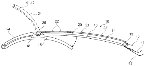
A wiper device 10 for cleaning a vehicle windscreen
(not shown) is depicted in Fig. 1. The wiper device 10
is preferably used on rear vehicle windscreens,
although it is also suitable in principle for the area
of application of front windscreens.
The wiper device 10 exhibits a wiper arm 11, which is
pivot-mounted on a wiper arm joint 12 in an axis 13. A
wiper blade 15 is fastened exchangeably on a wiper arm
11, which exhibits a wiper lip 16 on the side facing
the vehicle windscreen (Fig. 2). The wiper blade 15 is
fastened to the wiper arm 11 by means of a wiper blade
adapter 18, wherein for the configuration or the nature
of the fastening of the wiper blade 15 to the wiper arm
CA 02796960 2012-11-21
-6-
11, a plurality of different constructions or
arrangements can be used, as are already known per se
from the state of the art, because they are not
essential to the invention. All that is important for
the function of the wiper blade 15 is that it is
pivotably mounted on the wiper arm 11 in a rotation
axis 19, so that it is particularly able to adjust to
the contour of the vehicle windscreen during movement
of the wiper blade 15 over the vehicle windscreen.
The wiper arm 11 forms a cover 20 which contains the
wiper blade 15 over its entire length on the side
facing away from the vehicle windscreen, at least in
the area of the wiper blade 15. As is particularly
evident from Fig. 4 and Fig. 5, the cover 20 has a
substantially U-shaped cross-section, at least in the
area of the wiper blade 15. Along the upper side 21 of
the cover 20, recesses or openings 22 may be provided.
The cover 20 exhibits a first part 23 on the side of
the wiper arm joint 12, to which a second part 24 is
attached on the side facing away from the wiper arm
joint 12. The second part 24 is pivot-mounted to the
first part 23 on an axis 25, wherein the pivoted
position of the second part 24, which is assumed when a
wiper blade 15 on the wiper arm 11 is to be replaced,
is depicted by means of a dotted line in Fig. 1. The
arrangement of the axis 25 is such that the wiper blade
15 is accessible to a user in the area of the wiper
blade adapter 18 when the second part 24 is pivoted, so
that said user can replace the wiper blade 15 on the
wiper arm 11 without difficulty.
In the exemplary embodiment shown, the cover 20 is an
integral part of the wiper arm 11, such that at least
the first part 23 is formed by the wiper arm 11. In
this case, the first part 23 of the wiper arm 11 is
configured as a press-bent part. The second part 24 of
the wiper arm 11 or the cover 20 may likewise be made
CA 02796960 2012-11-21
- 7 -
of metal, as with the wiper arm 11 or the first part
23. It is also possible, however, for the second part
24 to be made of plastic. Furthermore, it is
conceivable in principle for the cover 20 also to be
configured as a separate part from the wiper arm 11.
As is most clearly evident from Fig. 3, the first part
23 exhibits openings 27 formed in link-type extensions
26 for the pivotable arrangement of the second part 24,
with which pin-like extensions 28 of the second part 24
engage. In order to securely connect the second part 24
to the wiper blade 15 with the second part 24 in the
operating position, so as to prevent the second part 24
from automatically moving into the position which
enables the wiper blade 15 to be replaced, a catch
connection 30 is configured between the second part 24
and the wiper blade 15.
As can be seen from Fig. 3 and Fig. 4 taken together,
the catch connection 30 comprises catch tongues 31, 32
arranged on both longitudinal sides of the wiper blade
15 or else of the cover 20, formed integrally with the
cover 20, each of which exhibits a receptacle 33, 34
being U-shaped in cross-section, said receptacles
interacting with areas of spring strips 35, 36
projecting laterally from the wiper blade 15 to
configure the catch connection 30. To release the catch
connection 30, the catch tongues 31, 32 need simply to
be pivoted in the direction of the arrows 37, 38.
It is provided according to the invention that the
wiper device 10 exhibits a spray device 40 for applying
washing fluid to the vehicle windscreen. The spray
device 40 comprises at least one, but in the exemplary
embodiment depicted in the figures, two washing fluid
hoses 41, 42. The two washing fluid hoses 41, 42 are
conducted within the wiper arm 11 or the cover 20 and
connected on the vehicle side to a storage container
CA 02796960 2012-11-21
- 8 -
for the washing fluid. The end sections of the two
washing fluid hoses 41, 42 facing the wiper blade 15
engage with two plug-like extensions 43, 44 shown in
Fig. 3, which tightly close the washing fluid hoses 41,
42 hydraulically. The two washing fluid hoses 41, 42
are arranged along the two longitudinal sides of the
wiper blade 15 or else fastened in the cover 20,
wherein the configuration of the washing liquid hoses
41, 42 is preferably in the area of the underside of
the cover 20 facing the vehicle windscreen, as is
represented by means of Fig. 5 to Fig. 7. It is
moreover evident from Fig. 5 that the two washing fluid
hoses 41, 42 are conducted by means of transverse ribs
45, 46 in the cover 20 in the area of the cover 20.
In Fig. 6 and Fig. 7, by contrast, a fastening of a
washing fluid hose 41a or 41b is depicted, in which the
washing fluid hose 41a, 41b exhibits a hook-shaped
extension 47 on its upper side facing away from the
vehicle windscreen, which may either be fitted on a
carrier 48 which is formed by a blank in the cover 20
according to Fig. 6, or on an inwardly curved holding
portion 49 of the cover 20 according to Fig. 7.
The washing fluid hoses 41, 42 and 41a, 41b exhibit
nozzle openings 50 on the side facing the vehicle
windscreen, which, as is only evident from Fig. 5, each
form a washing fluid jet 51 when the spray device 40 is
operated. It is essential for the nozzle openings 50
only to be formed in the area of the cover 20 or of the
wiper blade 15 in which the wiper blade 15 is situated.
The use of a washing fluid hose 41, 42 and 41a, 41b has
the advantage that when the second part 24 of the cover
20 is pivoted into the position shown by a dotted line
in Fig. 1, the washing fluid hose concerned 41, 42 or
41a, 41b can be pivoted without additional measures.
CA 02796960 2012-11-21
- 9 -
As a variation to the exemplary embodiments of the
spray device 40 shown in the figures, it is also
conceivable for the nozzle openings 50 to be configured
as an integral component of the cover 20, in that the
cover 20 exhibits corresponding washing fluid ducts on
the underside facing the vehicle windscreen and the
nozzle openings 50 are configured as bores in the cover
20, which open into the washing fluid ducts. In this
case, however, additional provisions must be made in
order to achieve pivotability between the two parts 23,
24, i.e. in the dividing point between the two parts
23, 24 in the area of the washing fluid ducts,
corresponding sealing measures are taken.
In addition, it may be provided that alongside the
spray device 40 a heating device 60 is also provided,
which serves to safeguard the functioning of the spray
device 40 at low temperatures. For this purpose, the
heating device 60, as can only be seen from Fig. 3,
comprises at least one heating wire 61, 62, which is
arranged within the cross-section of the washing fluid
hose 41, 42 or 41a, 41b, as is shown in greatly
simplified form in Fig. 3. The heating wires 61, 62 are
electrically coupled to a voltage supply.
The wiper device 10 described thus far may be changed
or modified in multifarious ways without deviating from
the basic idea underlying the invention. This idea is
that a spray device 40 is provided in the area of a
cover 20 for the wiper blade 15, wherein the wiper
blade 15 may be of any design and requires no
additional measures in relation to the spray device 40.
As a variation to the invention, it is also conceivable
that the cover and therefore also the spray device 40
does not extend over the entire length of the wiper
blade 15. However, the cover 20 or the spray device 40
should extend at least substantially, i.e. at least by
roughly 80%, over the length of the wiper blade 15.
CA 02796960 2012-11-21
- 10 -
Reference number list
Wiper device
5 11 Wiper arm
12 Wiper arm joint
13 Axis
Wiper blade
16 Wiper lip
10 18 Wiper blade adapter
19 Rotation axis
Cover
21 Upper side
22 Opening
15 23 First part
24 Second part
Axis
26 Link-like extension
20 28 27 OpeningPin-like extension
Catch connection
31 Catch tongue
32 Catch tongue
33 U-shaped receptacle
25 34 U-shaped receptacle
Spring strip
36 Spring strip
37 Arrow
30 40 38 Arrow Spray device
41 Washing fluid hose
41a Washing fluid hose
41b Washing fluid hose
42 Washing fluid hose
35 43 Plug-like extension
44 Plug-like extension
Transverse rib
46 Transverse rib
47 Hook-shaped extension
CA 02796960 2012-11-21
- 11 -
48 Carrier
49 Holding segment
50 Nozzle opening
51 Washing fluid jet
60 Heating device
61 Heating wire
62 Heating wire