Note: Descriptions are shown in the official language in which they were submitted.
CA 02796987 2012-10-19
WO 2011/134058 PCT/CA2011/000476
MAXIMUM POWER POINT TRACKING FOR A POWER GENERATOR
Field
This invention relates to circuits, systems, and methods for obtaining power
from a
power generator. In particular, the circuits, systems, and methods described
herein may be
used to maximize the power obtained from the power generator.
Background
Grid-connected power generation systems typically include two major parts:
power
generators that produce the power and inverters that receive, condition, and
inject the power
into the power distribution grid. Power generators include, for example,
photovoltaic (PV)
cells and wind turbines.
Power generators may be configured as: centralized, string, multi-string, and
AC-
module/cell technologies. To increase the overall efficiency of power
generators under
different conditions, such as varying wind conditions on wind turbines,
partial shadowing of
PV cells, or mismatches between PV cells, independent control and power
extraction is
required for each power generator. This requires using a separate inverter,
i.e., a micro-
inverter", for each power generator. Power extraction from each power
generator may
enhanced if maximum power point tracking (MPPT) is be performed on each power
generator independently.
Maximum power point tracking of a PV cell in particular is challenging due to
the
nonlinear current-voltage characteristic and ever-changing nature of the
irradiation source.
1
CA 02796987 2012-10-19
WO 2011/134058 PCT/CA2011/000476
Conventional MPPT systems use an algorithm that finds the best operating point
and creates
a reference signal, or logical and relational operators, and are based on
trial and error or seek
and find to find the best operating point. These may be implemented in
software running on
microprocessors. Such approaches may lead to oscillation around the optimum
point, which
adversely impacts overall efficiency of the system. Moreover, trial and error
approaches
degrades efficiency for fast changing conditions. This drawback and the low
speed
characteristic of such approaches may be problematic in conditions such as
monotonic and
fast increase of the irradiation level.
Summary
Described herein is a maximum power point tracking method, comprising: (i)
sampling instantaneous output voltage and current of a power generator at a
first instant in
time and at a second instant in time to obtain first and second power samples,
wherein the
instantaneous voltage and current at the first instant in time are always
greater than the
instantaneous voltage and current at the second instant in time, or vice
versa; (ii) generating a
reference voltage or current signal from a difference of the first and second
power samples;
(iii) comparing the reference voltage or current to the instantaneous power
generator voltage
or current and generating at least one gating signal; and (iv) repeating (i)
to (iii) so as to
minimize the difference of the first and second power samples; wherein the
gating signal
affects magnitude of the output voltage and current of the power generator;
wherein the
maximum power point is tracked when the difference signal is minimized. In one
embodiment, generating a reference voltage or current signal from a difference
of the first
and second power samples may include using a proportional-integral (PI)
controller.
The method may include sweeping the output voltage of the power generator for
a
range of maximum power points, determining a global maximum power point, and
setting a
starting point for maximum power point tracking as close as possible to the
global maximum
power point.
Also described herein is a maximum power point tracker, comprising: (i)a
sampling
means that samples instantaneous output voltage and current of a power
generator at a first
instant in time and at a second instant in time to obtain first and second
power samples,
wherein the instantaneous voltage and current at the first instant in time are
always greater
than the instantaneous voltage and current at the second instant in time, or
vice versa; (ii) a
2
CA 02796987 2012-10-19
WO 2011/134058 PCT/CA2011/000476
subtractor that subtracts the first and second power samples to produce a
difference signal;
(iii) a means that generates a reference voltage or current signal from the
difference signal;
and (iv)a means that generates at least one gating signal by comparing the
reference voltage
or current signal to the instantaneous power generator voltage or current;
wherein the gating
signal minimizes the difference of the first and second power samples; wherein
the maximum
power point is tracked when the difference signal is minimized. In one
embodiment, the
means that generates the reference voltage or current signal may comprise a
proportional-
integral (PI) controller.
In one embodiment a maximum power point tracker comprises means that sweeps
the
output voltage of the power generator for a range of maximum power points,
determines a
global maximum power point, and sets a starting point for maximum power point
tracking as
close as possible to the global maximum power point.
Also described herein is a micro-inverter for a power generator, comprising a
maximum power point tracker as described above and a power converter. The
power
converter may comprise a DC-DC converter and a DC-AC inverter. The power
converter
may generate a sinusoidal output current from the power generator output.
Also described herein is a power generation system, comprising a micro-
inverter as
described above and at least one power generator.
In the methods, circuits, and systems described herein, the power generator
may be a
photovoltaic cell, a wind turbine, or a fuel cell.
Brief Description of the Drawings
For a better understanding of the invention, and to show more clearly how it
may be
carried into effect, embodiments will now be described, by way of example,
with reference to
the accompanying drawings, wherein:
Figures 1(a) and (b) are generalized block diagrams of micro-inverter systems.
Figure 2(a) is a plot showing typical current-voltage and power-voltage
characteristics
and the maximum power point of a PV cell, and Figure 2(b) is a plot showing
how the
characteristics change with amount of irradiation.
3
CA 02796987 2012-10-19
WO 2011/134058 PCT/CA2011/000476
Figures 3(a) and (b) are diagrams of maximum power point tracking schemes
according to two embodiments.
Figures 4(a)-(d) are plots showing PV cell waveforms for different operating
points
relative to the maximum power point.
Figures 5(a)-(c) are plots showing results of a simulation of the embodiment
of Figure
3(a), for a step change and a sinusoidal change in the irradiation level at
(a) 20 ms and (b) 40
ms, respectively, with the error signal shown in (c).
Detailed Description of Embodiments
Described herein are systems, circuits, and methods for obtaining power from a
power
generator. A power generator may be, for example, a wind turbine, a fuel cell,
or a
photovoltaic cell. The power generator may be a distributed power generator.
Whereas
embodiments of the systems, circuits, and methods are described herein
primarily with
respect to photovoltaic cells, it will be appreciated that the systems,
circuits, and methods are
not limited thereto.
The systems, circuits, and methods described herein may be used in a micro-
inverter
for a power generator. As used herein, the term "micro-inverter" refers to a
device that
interfaces a power generator with a load, such as a power distribution grid. A
system
including a micro-inverter is shown in the generalized block diagram of Figure
1(a). The
micro-inverter 20 receives power from a power generator 10, and outputs power
to a load 30.
The micro-inverter 20 may include a power section 200 that may perform one or
more
functions, such as, for example, DC-DC conversion, DC to AC conversion, or a
combination
thereof. The micro-inverter may include a control section 300 that may perform
one or more
functions such as, for example, maximum power point tracking of the power
generator,
and/or providing gating signals to the power section 200. The gating signals
may be
determined by sensing the power generator voltage and/or current, and/or the
load voltage
and/or current.
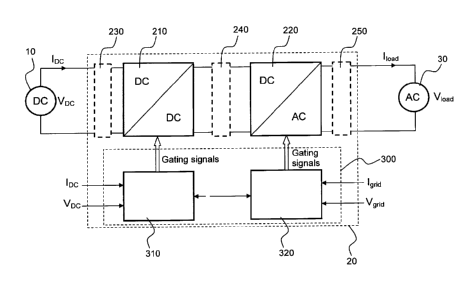
The generalized block diagram of Figure 1(b) shows an embodiment of a micro-
inverter that includes a power converter section 210 (e.g., DC-DC converter)
that receives
power from the power generator 10, and an inverter section 220 that receives
power from the
4
CA 02796987 2012-10-19
' WO 2011/134058
PCT/CA2011/000476
converter section 210 and produces output power. The output power may
optionally be
conditioned (e.g. filtered) 250 to be compatible with the load 30 (e.g., a
power distribution
grid). One or more passive component (e.g., a capacitor and/or an inductor)
may optionally
be employed at the power converter section 210 input and/or between the power
converter
section 210 and the inverter section 220 (i.e., at 230 and 240, respectively).
A filter 250 may
optionally be employed at the inverter section 220 output. A first controller
310 may sense
the power generator voltage and/or current and produce gating signals for
switches of the
power converter section 210. The first controller may perform maximum power
point
tracking. A second controller 320 may sense the voltage and/or current
delivered to the load
and produce gating signals for switches of the inverter section 220.
A micro-inverter as described herein increases the overall efficiency of the
power
generator under different circumstances and conditions. For example, in the
case of a PV cell
or a PV cell string that forms a PV module, partial shadowing of the PV cell
or mismatches
between PV cells can degrade the overall efficiency of the system. However,
use of a micro-
inverter for each PV cell, or for each PV cell string or module, permits
independent control
and power extraction from each PV cell or PV cell string or module, maximizing
efficiency
of the system despite varying conditions of individual PV cells, strings, or
modules.
A micro-inverter as described herein is compact, so as to be attached to a
power
generator (e.g., to the back of a PV cell). Since micro-inverters are exposed
to a wide range
of environmental conditions, such as extremes of temperature and humidity,
reliability and
maintenance are major issues. This exposure also adversely affects the life
expectancy and
performance of the inverter. These factors demand robust design and
construction, and may
require more expensive components that lead to a higher manufacturing cost.
Consequently,
challenges in the design of a micro-inverter are achieving compactness and low
cost, e.g., by
reducing the number and size of circuit components. Advantageously, a micro-
inverter as
described herein does not require costly high voltage components and wiring.
The controller
system may be implemented in whole or in part using discrete components, using
digital
technology (e.g., in a digital signal processor (DSP), field programmable gate
array (FPGA),
or application specific integrated circuit (ASIC) device), or using a
combination thereof. For
example, one or more components of the controller may be implemented in an
algorithm
using a suitable hardware language such as, for example, very high speed
integrated circuit
(VHSIC) hardware descriptive language (VHDL), register transfer language
(RTL), or
Verilog. Such an algorithm may be implemented in, for example, a FPGA or ASIC
device,
5
CA 02796987 2012-10-19
= WO 2011/134058
PCT/CA2011/000476
or other suitable logic device. Use of digital technology provides a
controller that is compact
and robust.
A micro-inverter as described herein may include maximum power point tracking
(MPPT). As a result, MPPT may be performed on each power generator
independently. A
challenge in using PV cells is presented by their nonlinear current-voltage (I-
V)
characteristics, which result in a unique maximum power point (MPP) on the
power-voltage
(P-V) curve, as shown in Figures 2(a) and (b). Thus, in the case of PV cells,
where partial
shading cannot be avoided, MPPT allows the maximum power to be extracted from
each PV
cell for any instantaneous condition. MPPT removes any mismatch losses between
PV cells
in the system. Further, micro-inverters as described herein provide modularity
to distributed
power generators, allowing a "plug and play" approach to their use in a
distributed power
generation system.
As used herein, the terms "maximum power point tracking (MPPT)" and "maximum
power point tracker (MPP tracker)" are distinct. "MPPT" refers to an algorithm
and "MPP
tracker" refers to hardware (i.e., a circuit). The MPPT calculates the optimum
operating
point for a power generator, and provides a reference point for MPP tracker to
steer the
system toward the optimum operating point.
As used herein, the term "photovoltaic cell" refers to any cell having a light
absorbing
material to absorb photons and generate electrons via a photoelectric effect.
A non-limiting
example of a photovoltaic cell is a solar cell. The light absorbing material
may absorb light
in any wavelength or combination of wavelengths, including, for example,
wavelengths of
solar light that reach the earth's surface, and/or wavelengths of solar light
beyond the earth's
atmosphere. Two or more light absorbing materials having specific wavelengths
of light
absorption may be used in combination to take advantage of different light
absorption and
charge separation mechanisms. The light absorbing material may be configured
as, for
example, bulk material, thin-film (e.g., inorganic layers, organic dyes, and
organic polymers),
and/or nanocrystals. The photovoltaic cells may be combined into arrays,
strings, modules,
or panels.
As used herein, the term "photovoltaic cell string" refers to a plurality of
photovoltaic
cells connected together in a series, parallel, series-parallel, or other
configuration. A PV cell
string may form a PV cell module.
6
CA 02796987 2012-10-19
WO 2011/134058 PCT/CA2011/000476
Maximum power point tracking as described here may be used with any converter,
such as, for example, a resonant-mode converter, a voltage source converter, a
current source
converter, etc.
Exemplary embodiments of a MPP tracker and a MPPT scheme are shown in Figures
3(a) and 3(b). In the following description, the embodiment shown in Figure
3(a) is
described with reference to the exemplary waveforms at different operating
points shown in
Figures 4(a) to (d). Operation of the embodiment shown in Figure 3(b) will be
readily
apparent to one or ordinary skill in the art based on the principle of
operation described
below.
Referring to Figures 3(a) and 4(a) to (d), the principle of operation may be
explained
as follows, using a PV cell as an example of a power generator 10. In this
embodiment an
input capacitor C1 is provided at the input of the DC-DC converter section
210. When the
DC-DC converter 210 switches are in positions such that the converter does not
draw power
from the PV cell, the PV cell will charge the input capacitor C1. As shown in
Figure 4(c), if
the average PV cell voltage at the operating point is much lower than the
maximum power
point (MPP), the power curve has the same slope as the voltage (the opposite
condition is
shown in Figure 4(a)). However, as shown in Figures 4(b) and (d), for the case
where the PV
cell voltage is increasing, the PV cell power increases and then decreases,
and passes through
the MPP. Therefore, as shown in Figure 4(d), if the control strategy forces
the PV cell to
satisfy Pp, (ti) = Pp, (t2), the MPP will always be tracked. Sampling of the
PV cell voltage
and current may be performed such that from t1 to t2 the voltage of the PV
cell increases.
Similarly for Figure 3(b), sampling of the PV cell voltage and current may be
performed such
that the current of the PV cell increases from t1 to t2. Sampling is
controlled by a timing
circuit as described below.
The embodiment of the control section 310 shown in Figure 3(a) or (b) includes
closed-loop feedback control. For example, control may be implemented by a
proportional-
integral (PI) controller 371 as shown in the figures. As noted above, all or
part of the control
section may be implemented in analog and/or digital (hardware/software)
platforms. For
example, an algorithm in a digital implementation may include the PI
controller. In the
embodiment shown in Figure 3(a) or (b) the PV cell instantaneous voltage and
current are
sampled, and the instantaneous power from the PV cell Pin is determined at
321. Using two
delay and sample blocks 341, 361, the instantaneous power Pin from the PV cell
is sampled at
7
CA 02796987 2012-10-19
WO 2011/134058 PCT/CA2011/000476
two switching instances (ti and t2) where the voltage increases monotonically.
The sampling
times are controlled by a timing circuit 351. The difference of these two
power values,
(Pin(ti) and Pin(t2)) is determined at 381, and gives a correct direction
towards the MPP. That
is, if the difference is negative, the PI controller 371 increases the set
point Vp7f to a point
where the two values (Ppv(ti) and Ppv(t2)) are equal, and vice versa (i.e., if
the difference is
positive, the PI controller 371 decreases the set point Vprve f to a point
where the two values
(Ppv(ti) and Ppv(t2)) are equal). The objective is to make this difference
zero. A control and
timing block 391 produces gating signals for the switches of the converter
210. The control
and timing block 391 may also provide power decoupling. Increasing or
decreasing the set
point Vpri,ef is performed while minimizing or avoiding any possible
oscillations and within a
short time interval. It will be appreciated that the method provides a very
fast response time
and does not use trial and error or any logical/relational operations, and
thereby avoids
misleading results typical of prior methods.
It is noted that the embodiments described herein permit the use of a small
value of
C1. The resulting short charge/discharge times of the capacitor facilitate
very fast maximum
power point tracking.
The embodiments of Figures 3(a) and (b) may be used substantially as shown or
with
other circuitry to produce a DC output power for use with a DC load or a DC
power
distribution system. The embodiments of Figures 3(a) and (b) may also be used
with further
circuitry such as an inverter circuit and suitable rectifier/filter circuits
(i.e., one or more of
sections 220, 240, 250, and 320 of Figure 1(b)) to produce AC output power
(e.g., 50 or 60
Hz) for use with an AC load or injected into a power distribution grid.
In some cases a PV cell characteristic may have more than one maximum power
point. Depending on the starting point of the algorithm, this may lead to a
situation in which
a power point tracking method, such as described herein, gets trapped in local
maximum
power points. To avoid such a situation, the method may include sweeping the
voltage of the
PV cell for the range of MPPs, determining a global maximum power point, and
setting the
starting point as close as possible to the global maximum power point. This
ensures that the
MPPT algorithm will always track the global maximum power point. The interval
at which
the voltage range of the PV cell is swept may be programmable and may depend
on factors
such as the PV cell/module configuration. Since the sweep can be performed
very fast, and
8
CA 02796987 2015-04-15
this situation normally does not happen often, the search for a global maximum
power point
does not affect the overall efficiency of the system. It is worth mentioning
that such a
condition is not specific to the method described herein; rather, any MPPT
algorithm may be
similarly affected.
The following non-limiting example is provided to further illustrate the
invention.
Working Example
An analogue simulation of the MPP tracker and MPPT control scheme shown in
Figure 3(a) was carried out for a PV cell, using the PV cell model in PSIMTm
version 9
(Powersim Inc., Woburn, MA). Irradiation was varied using a step change and a
sinusoidal
change at 20 Hz. Figure 5(a)-(c) shows the simulation results at the different
irradiation
levels. From Figure 5(c) it can be seen that for very fast changing
irradiation (the step
change) the error was maintained at a very low level. This improves the
overall efficiency of
the system.
Equivalents
Those skilled in the art will recognize or be able to ascertain variants of
the
embodiments described herein. Such variants are within the scope of the
invention and are
covered by the appended claims.
- 9 -