Note: Descriptions are shown in the official language in which they were submitted.
CA 02797009 2012-10-18
"Inerting method for preventing and/or extinguishing fire
as well as inerting system to realize the method"
Description
The present invention relates to an inerting method for preventing and/or
extin-
guishing fire in which in a predefinable oxygen content which is lower than
normal
ambient air is set and maintained in the spatial atmosphere of an enclosed
room.
The invention further relates to an inerting system to set and/or maintain a
predefinable oxygen content in the spatial atmosphere of an enclosed room
which
is reduced compared to the normal ambient air, wherein the inerting system
comprises a gas separation system which separates off at least a portion of
the
oxygen from an initial gas mixture containing nitrogen and oxygen and by so
doing, provides a nitrogen-enriched gas mixture at the outlet of the gas
separation system, and wherein the inerting system comprises a supply line
system for supplying the nitrogen-enriched gas mixture to the enclosed room.
An inerting system of the above type particularly relates to a system to
reduce the
risk of and extinguish fires in a protected room subject to monitoring,
wherein the
protected room is continuously rendered inert for the purpose of preventing or
controlling fire. The mode of action of such an inerting system is based on
the
recognition that the risk of fire in enclosed rooms can be countered by
continuously
lowering the concentration of oxygen in the respective area to a value of e.g.
approximately 12-15% by volume in normal cases. At such an oxygen concentra-
CA 02797009 2012-10-18
2
tion, most combustible materials can no longer ignite. The main areas of appli-
cation are in particular IT areas, electrical switchgear and distributor
compart-
ments, enclosed facilities as well as storage areas for high-value
commodities.
A method as well as a device of the type cited at the outset is known from the
EP 2 204 219 Al printed publication. A return system is employed here to
withdraw a portion of the ambient air from within the enclosed room and feed
it
to a mixing chamber. Fresh air is added to the portion of air withdrawn from
the
room in the mixing chamber. The gas mixture thus produced (initial gas
mixture)
is fed to a compressor to be compressed there and then channeled to a nitrogen
generator. The nitrogen generator separates off at least a portion of the
oxygen
from the initial gas mixture provided, thus producing a nitrogen-enriched gas
mixture at the outlet of the nitrogen generator. This nitrogenated gas mixture
is
thereafter piped into the enclosed room in order to lower the oxygen content
of
the room's spatial atmosphere to a predetermined inerting level or to maintain
it
at a preset inerting level.
In practice, the method of returning oxygen-reduced air employed in printed
publication EP 2 204 219 Al to enable a more effective nitrogen generation for
fire protection purposes calls for a return method which is adapted as
optimally
as possible to the gas separation system employed. Care must in particular be
taken that the initial gas mixture provided in the mixing chamber is always in
an
optimized state for the gas separation system to be employed. This requirement
is especially applicable when a plurality of nitrogen generators with
respectively
associated compressors are employed as the gas separation system. Care must
then in particular be taken that the respective suction action of each
individual
nitrogen generator has no impact on any of the other nitrogen generators. This
method has to factor in that a nitrogen generator which uses membrane
technology to separate gases needs to exhibit a constant suction action. On
the
other hand, when a nitrogen generator is employed which makes use of the
above-described PSA technology or the above-described VPSA technology to
separate gases, the fact that such a nitrogen generator can operate with
pulsed
suction action needs to be considered.
Particularly in large-volume areas such as for instance warehouses, it is
frequently
desired to use a plurality of nitrogen generators in parallel for setting and
maintaining a predefined or predefinable inerting level, whereby it can occur
that
CA 02797009 2012-10-18
3
the nitrogen generators are based on different gas separation technologies.
Such
a case requires a costly and independent return line for each nitrogen
generator
from the enclosed room to the respective nitrogen generator in order to ensure
the optimum operation of each nitrogen generator. This requirement leads to a
relatively complex structure to the inerting system.
Starting from this problem as posed, the present invention is based on the
task of
further developing the inerting system known from the EP 2 204 219 Al printed
publication, respectively the inerting method known from the EP 2 204 219 Al
printed publication, such that a predefined inerting level can be set and main-
tained in the enclosed room in the simplest yet most efficient manner
possible.
According to a first aspect of the invention related to the inerting method,
an
initial gas mixture containing oxygen, nitrogen and other components as
applicable is provided in a mixing chamber, wherein a gas separation system
separates off at least a portion of the oxygen from this initial gas mixture
provided
and by so doing, a nitrogen-enriched gas mixture is provided at the outlet of
the
gas separation system, and wherein this nitrogen-enriched gas mixture is piped
into the spatial atmosphere of the enclosed room. A return line system
connecting
the enclosed room to the mixing chamber is provided to supply the initial gas
mixture, wherein a fan mechanism is further provided to withdraw a portion of
the
ambient air from within the enclosed room, preferably in regulated manner, and
feed it to the mixing chamber, wherein the withdrawn portion of the room's air
is
admixed with fresh air, preferably in regulated manner, by means of a fan
mechanism provided in the fresh air-supply line system connected to the mixing
chamber.
A further aspect of the invention with respect to the method provides for the
fan
mechanism provided in the return supply line system to be controlled such that
the volume of air withdrawn from the room per unit of time and fed to the
mixing
chamber be set such that the difference between the pressure prevailing in the
mixing chamber and the pressure of the external ambient atmosphere does not
exceed a predefined or predefinable upper threshold nor fall short of a
predefined
or predefinable lower threshold.
A further aspect of the invention with respect to the method provides for the
fan
mechanism provided in the fresh air supply line system to be controlled such
that
CA 02797009 2012-10-18
4
the volume of fresh air mixed with the withdrawn volume of room air per unit
of
time is set such that the difference between the pressure prevailing in the
mixing
chamber and the pressure of the external ambient atmosphere does not exceed a
predefined or predefinable upper threshold nor fall short of a predefined or
predefinable lower threshold.
A further aspect of the invention relating to the inerting system provides for
the
inerting system to further comprise a mixing chamber, preferably a mixing
chamber configured as a mixing tube, which serves to provide the initial gas
mixture, wherein a first line system opens into the mixing chamber, with a
portion of the spatial air from inside the enclosed room being withdrawn and
fed
to the mixing chamber through said first line system, and wherein a second
line
system opens into the mixing chamber, with fresh air being supplied to the
mixing chamber through said second line system.
A further aspect of the invention with respect to the inerting system provides
for
the inerting system to further comprise a first fan mechanism controllable by
a
control unit in the first line system and a second fan mechanism system
controllable by the control unit in the second line.
A further aspect of the invention with respect to the inerting system provides
for
the control unit of an inerting system provided with such a control unit to be
designed so as to control the first fan mechanism such that the amount of air
withdrawn from the room per unit of time and fed to the mixing chamber by
means of said first fan mechanism can be set such that the difference between
the pressure prevailing in the mixing chamber and the pressure of the external
ambient atmosphere does not exceed a predefined or predefinable upper
threshold nor fall short of a predefined or predefinable lower threshold.
A further aspect of the invention with respect to the inerting system provides
for
the control unit of an inerting system provided with such a control unit to be
designed so as to control the second fan mechanism such that the volume of
fresh air admixed to the spatial air withdrawn from the room per unit of time
by
means of said second fan mechanism can be set such that the difference between
the pressure prevailing in the mixing chamber and the pressure of the external
ambient atmosphere does not exceed a predefined or predefinable upper
threshold nor fall short of a predefined or predefinable lower threshold.
CA 02797009 2012-10-18
A further aspect of the invention with respect to the inerting system provides
for
the inerting system to comprise a control unit which is designed to control
the
gas separation system such that the residual oxygen content of the nitrogen-
enriched gas mixture is changed as a function of the oxygen content prevailing
in
the spatial atmosphere of the enclosed room at that respective moment.
The resulting preventative or extinguishing effect of this inerting method is
based
on the principle of oxygen displacement. As is generally known, normal ambient
air consists of about 21% oxygen by volume, about 78% nitrogen by volume and
about 1% by volume of other gases. In order to be able to effectively reduce
the
risk of a fire breaking out in a protected room, the concentration of oxygen
in the
respective room is lowered by introducing inert gas such as e.g. nitrogen. For
most solids, a fire-extinguishing effect is known to occur when the percentage
of
oxygen falls below 15% by volume. Depending on the flammable materials
contained within a protected room, a further lowering of the oxygen percentage
to e.g. 12% by volume may be necessary. Thus, continuously rendering a
protected room inert will also effectively minimize the risk of a fire
breaking out
in said protected room.
The inventive method, inerting system respectively, capitalizes on the
knowledge
that the nitrogen purity of the nitrogenated gas mixture provided at the
outlet of
the gas separation system, respectively the residual oxygen content of the
nitrogenated gas mixture provided at the outlet of the gas separation system,
has
an effect on the so-called "drawdown time." The term "drawdown time" refers to
the length of time required to set a predefined inerting level in the spatial
atmosphere of the enclosed room.
The specific knowledge capitalized on herein is that as nitrogen purity
increases,
the air factor of the gas separation system rises exponentially.
The term "air factor" refers to the ratio of the volume of initial gas mixture
pro-
vided the gas separation system per unit of time to the volume of nitrogenated
gas
provided at the outlet of the gas separation system per unit of time. A
nitrogen
generator will usually allow the arbitrary selection of any nitrogen purity
desired at
the outlet of the gas separation system, with this value able to be set on the
nitrogen generator itself. Generally speaking, the lower the nitrogen purity
is set,
CA 02797009 2012-10-18
6
the lower the operating costs for the nitrogen generator will be. In
particular, the
compressor then only needs to run for a comparatively shorter period of time
when
providing a nitrogenated gas mixture at the set nitrogen purity at the outlet
of the
gas separation system.
With respect to the costs incurred to operate the inerting system to inert the
room,
however, other additional factors need to be taken into account. These
particularly
include the purge factors involved in displacing the oxygen in the spatial
atmosphere of the enclosed room by means of the nitrogen-enriched gas mixture
provided at the outlet of the gas separation system until the predefined
inerting
level is reached, respectively maintained. These purge factors particularly
include
the amount of nitrogenated gas provided by the gas separation system per unit
of
time, the spatial volume of the enclosed room, and the difference between the
oxygen content prevailing in the spatial atmosphere of the enclosed room at
that
respective moment versus the oxygen content corresponding to the predefined
inerting level. To be hereby considered is that in terms of the drawdown time,
the
nitrogen purity of the gas mixture provided at the outlet of the gas
separation
system, respectively the residual oxygen content of the nitrogenated gas
mixture,
likewise plays a crucial role, since the purging operation goes faster the
lower the
residual oxygen content in the nitrogenated gas mixture.
The term "gas separation system" as used herein is to be understood as a
system
which can effect the separation of an initial gas mixture comprising at least
the
components of "oxygen" and "nitrogen" into an oxygen-enriched gas as well as a
nitrogen-enriched gas. The functioning of such a gas separation system is
usually
based on the effect of gas separation membranes. The gas separation system
used in the present invention is primarily designed to separate oxygen from
the
initial gas mixture. This type of gas separation system is frequently also
referred
to as a "nitrogen generator."
This type of gas separation system makes use of a membrane module or the like,
for example, whereby the different components contained in the initial gas
mixture (e.g. oxygen, nitrogen, noble gases, etc.) diffuse through the
membrane
at different speeds based on their molecular structure. A hollow fiber
membrane
can be used as the membrane. Oxygen, carbon dioxide and hydrogen have a high
diffusion rate and because of that, escape from the initial gas mixture
relatively
quickly when passing through the membrane module. Nitrogen having a low
CA 02797009 2012-10-18
7
diffusion rate percolates through the hollow fiber membrane of the membrane
module very slowly and thereby concentrates when passing through said hollow
fiber/membrane module. The nitrogen purity, the residual oxygen content
respectively, of the gas mixture exiting the gas separation system is
determined
by the flow velocity. Varying the pressure and the volumetric flow rate allows
the
gas separation system to be adjusted to the required nitrogen purity and
necessary volume of nitrogen. Specifically, the purity of the nitrogen is
regulated
by the speed at which the gas passes through the membrane (dwell time).
The separated oxygen-enriched gas mixture is usually concentrated and
discharged into the environment at atmospheric pressure. The compressed,
nitrogen-enriched gas mixture is provided at the outlet of the gas separation
system. An analysis of the product gas composition ensues by measuring the
residual oxygen content in volume percent. The nitrogen content is calculated
by
subtracting the measured residual oxygen content from 100%. In so doing, it
needs to be considered that although this value is designated as the nitrogen
content or the nitrogen purity, it is in fact the inert content as this
component is
not only comprised of just nitrogen but also other gas components such as for
example noble gases.
The gas separation system, nitrogen generator respectively, is usually fed
compressed air which has been purified by upstream filter units. It is in
principle
conceivable to use a pressure swing process (PSA technology) utilizing two
molecular sieve beds to provide the nitrogen-enriched gas, wherein the two
sieves are alternatingly switched from a filter mode to a regeneration mode,
thereby yielding the flow of nitrogen-enriched gas.
As long as it is not imperative to have a continuous flow of nitrogen-enriched
gas
at the outlet of a pressure swing-operating nitrogen generator, just one
molecular sieve bed can also be used which is alternatingly switched into an
adsorption mode upon the application of pressure, during which the nitrogen-
enriched gas is provided at the outlet, and thereafter into a desorption mode
at
lower pressure during which the oxygen-enriched air within the proximity of
the
molecular sieve bed can be purged off.
When a nitrogen generator utilizes for example a membrane technology, the
process capitalizes on the general knowledge that different gases diffuse
through
CA 02797009 2012-10-18
8
materials at different speeds. In the case of nitrogen generators, the
different
diffusion rates of the principal components of air; i.e. nitrogen, oxygen and
water
vapor, are used to generate a flow of nitrogen, respectively nitrogen-enriched
air.
In detail, to technically realize a membrane technology-based nitrogen
generator,
a separation material through which water vapor and oxygen can readily
diffuse,
but which only affords a low diffusion rate for nitrogen, is applied to the
outer
surfaces of the hollow fiber membranes. When air flows through the inside of
such
a treated hollow fiber, the water vapor and oxygen quickly diffuse outward
through the hollow fiber wall while the nitrogen is largely retained within
the fiber
such that a strong concentration of nitrogen builds up during passage through
the
hollow fiber. The effectiveness of this separation process essentially depends
on
the flow rate in the fiber and the pressure differential over the hollow fiber
wall.
With a decreasing flow rate and/or a higher pressure differential between the
interior and the exterior of the hollow fiber membrane, the purity of the
resultant
nitrogen flow increases. Generally speaking, a membrane technology-based
nitrogen generator can thus regulate the degree of nitrogenization to the
nitrogenated air provided by the nitrogen generator as a function of the dwell
time
of the compressed air provided by the compressed air source in the air
separation
system of the nitrogen generator.
If, on the other hand, the nitrogen generator is for example based on PSA
technology, specially-treated activated charcoal makes use of the different
binding rates of the atmospheric oxygen and atmospheric nitrogen. The
structure
of the activated charcoal employed is thereby changed such that a large number
of micropores and submicropores (d < 1 nm) develop over an extremely large
surface area. At this pore size, the oxygen molecules of the air diffuse into
the
pores substantially faster than the nitrogen molecules such that the air in
the
proximity of the activated charcoal becomes enriched with nitrogen. A PSA
technology-based nitrogen generator can thus ¨ as is also the case with a
membrane technology-based generator ¨ regulate the degree of nitrogenization
to the nitrogenated air provided by the nitrogen generator as a function of
the
dwell time of the compressed air provided by the compressed air source in the
nitrogen generator.
As described above, these types of PSA technology-based nitrogen generators
need to be alternately operated in an adsorption mode and a desorption mode,
whereby pressure has to be applied to the molecular sieve bed during the
CA 02797009 2012-10-18
9
adsorption mode (filter mode) in order to ensure sufficient diffusion of
oxygen
molecules in the pores of the activated charcoal (carbon granules, CMS) for
the
generating process. Compared to the higher sieve bed pressure versus the
ambient pressure during the adsorption phase, the pressure is reduced during
the
subsequent desorption phase (purge or regeneration phase) in order to enable
effective purging of the carbon granules.
Standard PSA nitrogen generators, which are also called pressure swing adsorp-
tion generators for this reason, use a pressure level substantially
corresponding
to the ambient pressure during the regeneration cycle (desorption phase).
Compared to such standard pressure swing adsorption generators, so-called
vacuum pressure swing adsorption generators (VPSA technology) are of more
complex configuration, their desorption process is thereby intensified,
respectively shortened, by the fact that not only is the pressure reduced to
the
level of the ambient pressure but also a pressure approaching a vacuum
pressure
level, which is lower than the ambient pressure, is actively established in
the
proximity of the molecular sieve bed to be regenerated. To do so, it is then
necessary to provide, in addition to the increased pressure level provided by
the
compressor, also a corresponding reduced pressure approaching a vacuum
pressure level, for which a vacuum source is usually needed. Such a vacuum
source can be in the form of a vacuum pump, for example.
As indicated above, the inventive solution makes use of the knowledge that the
air
factor of the gas separation system increases exponentially with increasing
nitrogen purity on the one hand and, on the other, that in order to set a
predefined inerting level, the compressor used in the inerting system has to
run
for a longer period of time the lower the difference is between the oxygen
content
prevailing in the spatial atmosphere of the enclosed room at that respective
moment and the residual oxygen content in the nitrogenated gas mixture. It is
hereby to be taken into account that the power consumption of the inerting
system is virtually directly proportional to the length of time the drawdown
process takes to render a room inert, whether when setting the room at a fixed
residual oxygen content or when lowering to a new reduced level, since the
compressor upstream of the gas separation system is digitally driven to its
operating point at optimum efficiency.
CA 02797009 2012-10-18
It thus remains to be noted that ¨ when a lower value of e.g. only 90% by
volume is selected for the nitrogen purity ¨ the inert gas system has to run
for a
relatively long period of time in order to set an inerting level. Should the
nitrogen
purity value be raised for example to 95% by volume, the difference between
the
oxygen content of the inerting level to be set and the residual oxygen content
of
the gas mixture provided at the outlet of the gas separation system likewise
increases, which thereby reduces the amount of runtime the compressor needs to
set an inerting level, and thus lowers the power consumption of the inerting
system. However the circumstance of increasing the nitrogen purity at the
outlet
of the gas separation system inevitably also increases the air factor. The
circumstance has a negative effect on the runtime of the compressor necessary
to set an inerting level, respectively the power consumption of the inerting
system. This negative effect prevails if the increase in the air factor due to
increasing the nitrogen purity becomes appreciable.
Unlike with the usual systems known from the prior art where a fixed value is
selected for the nitrogen purity of the gas separation system, the present
invention is based on an inerting system in which, when the enclosed room is
being rendered inert, the residual oxygen content provided at the outlet of
the
gas separation system and the nitrogen-enriched gas mixture is preferably
automatically or selectively adjusted to the oxygen content prevailing at that
respective moment in the spatial atmosphere of the enclosed room in order to
thus set the nitrogen purity of the gas separation system to a value which is
optimized in terms of the time required.
The phrase "time-optimized nitrogen purity value" as used herein refers to the
nitrogen purity of the gas separation system, the residual oxygen content
respectively, provided at the outlet of the gas separation system and the
nitrogen-enriched gas mixture with which a defined inerting system, in which
the
volume of nitrogenated gas mixture able to be provided per unit of time is
constant, assumes a minimum time period for lowering from a current oxygen
content to a predefined oxygen content corresponding to a given inerting
level.
Being able to set the volume of room air withdrawn from the room per unit of
time and fed to the mixing chamber and/or the volume of fresh air added to the
withdrawn portion of the room air per unit of time such that the difference
between the pressure prevailing in the mixing chamber and the ambient
CA 02797009 2012-10-18
11
atmospheric pressure does not exceed a predefined or predefinable upper
threshold nor fall short of a predefined or predefinable lower threshold
ensures
that the initial gas mixture provided at the outlet of the mixing chamber is
always
in a defined state and optimally adapted to the gas separation system. The
inventive solution in particular allows gas separation systems utilizing a
plurality
of nitrogen generators, whereby said plurality of nitrogen generators can also
be
based on differing gas separation technologies. Particularly ensured with the
inventive solution is that the respective suction action of the plurality of
nitrogen
generators applicably employed will not interact with the other nitrogen
generators provided. It is therefore readily feasible for the inventive
solution to
also be employed as a fire extinguishing system or a fire prevention measure
in
large-volume rooms, for instance warehouses, by using multiple and potentially
different nitrogen generators therein for the gas separation, without the need
for
a costly, independent and regulated return line for each nitrogen generator
from
the protected room to the respective nitrogen generator. Accordingly, the
adapted return method proposed by the inventive solution avoids increased
expenditure in realizing the inventive inerting system.
The solution according to the invention in particular also lowers the
operational
costs required to produce the inerting effect in a simple to realize yet
effective
manner, in particular also in the case of relatively large-volume rooms such
as
warehouses, for example.
A further aspect of the invention provides for the upper pressure differential
threshold to be 1.0 mbar, preferably 0.5 mbar, whereby the lower pressure
differential threshold is preferably 0.0 mbar. Having the difference between
the
pressure prevailing in the mixing chamber and the external atmospheric
pressure
being within this indicated range always ensures that the respective suction
action of the nitrogen generators employed (a constant suction action for a
nitrogen generator which uses membrane technology for the gas separation or a
pulsed suction action for a nitrogen generator which uses PSA or VPSA
technology for the gas separation) will be a non-interacting action. Of course
other values are also conceivable for the upper and/or lower threshold.
A further aspect of the invention provides for a control unit-regulated first
fan
mechanism in a first line system via which a portion of the spatial air
contained
within the enclosed room is withdrawn from the room in a manner regulated by
CA 02797009 2012-10-18
12
said control unit and fed to the mixing chamber. Of further advantage is the
providing of a second control unit-regulated fan mechanism in a second line
system, via which fresh air is supplied to the mixing chamber in regulated
fashion.
The control unit should thereby be designed to control the first and/or second
fan
mechanism such that the volume of spatial air withdrawn from the room per unit
of time is identical to the volume of the nitrogen-enriched gas mixture which
is
supplied to the spatial atmosphere of the enclosed room per unit of time.
Providing the correspondingly controllable fan mechanisms can further maintain
the difference between the pressure prevailing in the mixing chamber and the
external ambient atmospheric pressure (within a certain control range) at a
predefined or predefinable value in a simple to realize yet effective manner.
This
thus ensures that the initial gas mixture is provided to the respectively
utilized
nitrogen generators of the gas separation system in an optimally adapted
state.
According to a further aspect of the invention, the volume of fresh air which
is
admixed with the spatial air withdrawn from the room in the mixing chamber per
unit of time is selected such that the volume of spatial air withdrawn from
the
room per unit of time is identical to the volume of the nitrogen-enriched gas
mixture which is piped into the spatial atmosphere of the enclosed room per
unit
of time. This thereby ensures that no excess or negative pressure will develop
by
introducing the nitrogenated gas mixture into the spatial atmosphere of the
enclosed room or by the discharging/return of the spatial air from the
enclosed
room respectively.
To provide the initial gas mixture, a further aspect of the invention provides
for a
mixing section into which open the first line system, through which a portion
of
the air contained in the enclosed room is withdrawn from the room in regulated
manner, and the second line system, by way of which fresh air is supplied in
regulated manner, preferably by means of a Y-connector. This mixing section is
either integrated into the mixing chamber or upstream of the mixing chamber.
The mixing section serves to mix the spatial air withdrawn from the enclosed
room with the fresh air as supplied and is configured ¨ in order to ensure
optimum mixing ¨ so that a turbulent flow will occur in the mixing section. To
this end, it is conceivable to correspondingly reduce the mixing section's
effective
flow cross-section such that a flow rate is set for the fresh air introduced
into
the mixing section and the return room air likewise introduced into the mixing
section which is greater than the characteristic Reynolds number-dependent
CA 02797009 2012-10-18
13
limiting velocity. Alternatively or additionally hereto, it is conceivable to
provide
spoiler elements in the mixing section in order to induce a turbulent flow in
said
mixing section.
In the latter embodiment cited in which a mixing section is integrated into
the
mixing chamber or arranged upstream of the mixing chamber for the turbulent
mixing of the return room air and the supplied fresh air, a further aspect of
the
invention provides for the mixing section to exhibit a length sufficiently
long
enough to effect the most complete and even mixing of the return room air
and supplied fresh air as possible. It is particularly preferred here for the
mixing section to be of a length which is at least five times that of the
mixing
section's hydraulic diameter. The hydraulic diameter is a theoretical
dimension
for calculations related to tubes or channels of non-circular cross sections.
This
term then allows making calculations as with a round tube. It is the quotient
of
four times the flow cross section and the wetted perimeter (inner and outer as
applicable) of a measurement cross section.
A further aspect of the invention provides for the gas separation system to
comprise at least one and preferably a plurality of nitrogen generators each
associated with a respective compressor connected to the mixing chamber by
means of a line system. The residual oxygen content provided at the outlet of
the
nitrogen generator and the nitrogen-enriched gas mixture is adjustable for
each
nitrogen generator by means of the control unit. This realization is in
particular
suitable for protecting large volume areas such as for instance a warehouse.
A further aspect of the invention provides for the gas separation system's at
least
one nitrogen generator, at least one of the plurality of nitrogen generators
respectively, to be configured as a vacuum pressure swing adsorption
generator;
i.e. in other words, one which functions according to VPSA technology. In the
case of such a vacuum pressure swing adsorption generator, a line system is
additionally provided between the mixing chamber and at least one inlet of the
vacuum pressure swing adsorption generator. A controllable intermediate valve
having a control connection to the control unit is active in this line system.
The
control unit can thus effect a direct controllable connection between the
mixing
chamber and the at least one inlet of the vacuum pressure swing adsorption
generator. In conjunction with the method according to the invention, it is
then
provided that during the desorption phase of the vacuum pressure swing
CA 02797009 2012-10-18
14
adsorption generator and for example a few seconds before the desorption phase
is scheduled to end, for example five seconds before the scheduled end of the
desorption phase, the intermediate valve in the line system connecting the
mixing
chamber and the nitrogen generator is brought from a closed position into an
open position allowing passage so that the mixing chamber is directly
connected
to at least one inlet of the vacuum pressure swing adsorption generator prior
to
the end of the vacuum pressure swing adsorption generator's desorption phase.
A further aspect of the invention provides for the nitrogen generator of the
gas
separation system configured as a vacuum pressure swing adsorption generator
to comprise at least one inlet, wherein the at least one inlet is selectively
connected to the pressure side of a compressor or to the suction side of a
vacuum source by means of a line system.
According to a further aspect of the invention with a nitrogen generator of
the gas
separation system configured as a vacuum pressure swing adsorption generator
having at least one inlet, the at least one inlet of the nitrogen generator is
connected to the suction side of the vacuum source during a desorption phase.
According to a further aspect of the invention with a nitrogen generator of
the
gas separation system configured as a vacuum pressure swing adsorption
generator, at least one inlet of the nitrogen generator is selectively
connected to
the mixing chamber by means of a line system.
According to a further aspect of the invention with a nitrogen generator of
the gas
separation system configured as a vacuum pressure swing adsorption generator
having at least one inlet, the at least one inlet of the nitrogen generator is
connected to the mixing chamber by means of a line system to end a desorption
phase of the nitrogen generator.
Since a negative pressure prevails at this inlet of the vacuum pressure swing
adsorption generator during the desorption phase, nitrogen-enriched air from
the
mixing container is automatically provided into this inlet of the vacuum
pressure
swing adsorption generator prior to the end of the desorption phase, which
leads
for example to an adsorption bed containing carbon granules (CMS). A passive
increase in pressure thus occurs in such an adsorption bed (CMS container) so
that the desorption phase for this vacuum pressure swing adsorption generator
CA 02797009 2012-10-18
can be passively ended without any additional expenditure of energy which
saves
time and energy compared to conventional solutions. Furthermore, when the
pressure swing adsorption generator is then thereafter switched into a
subsequent
adsorption operation, such a passive increase in pressure in the adsorption
bed
(CMS container) enables the vacuum pressure swing adsorption generator to be
switched into adsorption operation possible without the compressor load that
would otherwise be necessary to regenerate a pressure in the area of the
adsorption bed for the subsequent adsorption operation which is closer to the
excess pressure subsequently created during the adsorption phase. What this
realizes is that the compressor associated with the vacuum pressure swing
adsorption generator can bring the molecular sieve bed back to the operating
pressure in a shorter amount of time, whereby nitrogen is then in turn
generated
faster at the outlet of the vacuum pressure swing adsorption generator.
Moreover,
because air which is already nitrogenated flows from the mixing chamber toward
the molecular sieve bed, the oxygen level during the subsequent adsorption
phase
already starts at a lower level. The appropriate design to the mixing chamber,
for
example preferably as a long mixing tube, in turn yields advantageous pressure
fluctuation-compensating properties so that even the early end of a pressure
equalization procedure in such a desorption phase of the vacuum pressure swing
adsorption generator will not have any impact on for example any other of the
plurality of nitrogen generators. In other words, ensuring the continued non-
interacting operation of all the nitrogen generators employed.
With respect to the mixing chamber employed in the inventive solution, a
further
aspect of the invention provides for said mixing chamber to exhibit a volume
which is dependent on the number of nitrogen generators used in the inerting
system and/or on the principle on which the functioning of the least one
nitrogen
generator is based. The volume of the mixing chamber is to in particular be
selected such that the respective suction action of the nitrogen generators
employed will be a non-interacting action for all nitrogen generators.
In accordance with a further aspect of the invention, the mixing chamber is
hereby further configured such that the maximum flow rate which can occur in
the mixing chamber is less than 0.1 m/s on average. This is attained by
suitably
selecting the mixing chamber's hydraulic cross section.
CA 02797009 2012-10-18
16
A further aspect of the invention provides for the residual oxygen content of
the
nitrogen-enriched gas mixture, the nitrogen purity of the gas separation
system
respectively, to preferably be set automatically according to a predetermined
characteristic curve.
A further aspect of the invention provides for such a characteristic curve to
specify the time-optimized behavior of the residual oxygen content in the
nitrogenated gas mixture in relation to the oxygen content in the spatial
atmosphere of the enclosed room, according to which the inerting process can
set
a predefinable reduced oxygen content in the spatial atmosphere of the
enclosed
room compared to the normal ambient air in the shortest amount of time.
The phrase "time-optimized behavior of the residual oxygen content" refers to
the
time-optimized value of the residual oxygen content dependent on the oxygen
content in the spatial atmosphere of the enclosed room. As indicated above,
the
time-optimized value of the residual oxygen content corresponds to the value
of
the residual oxygen content to be selected for the gas separation system such
that the inerting method can set a predefinable oxygen content in the spatial
atmosphere of the enclosed room which is reduced compared to the normal
ambient air within the shortest amount of time.
The characteristic curve, according to which the residual oxygen content is
set
as a factor of the oxygen content prevailing at that respective moment in the
spatial atmosphere of the enclosed room is predetermined (measured or
calculated) for the gas separation system/inerting system.
Since one aspect of the inventive solution relates to the setting of the
nitrogen
purity of the gas separation system, or the residual oxygen content in the
nitrogen-enriched gas mixture respectively, as a function of the oxygen
content
prevailing in the spatial atmosphere of the enclosed room at that respective
moment and according to a further aspect of the inventive solution, the
nitrogen
purity of the gas separation system, the residual oxygen content in the
nitrogen-
enriched gas mixture respectively, is automatically set as a function of the
oxygen content prevailing in the spatial atmosphere of the enclosed room at
that
respective moment so as to thereby be able to render the room inert at the
lowest possible operating costs, a further aspect of the invention provides
for
either directly or indirectly measuring the current oxygen content in the
spatial
CA 02797009 2012-10-18
17
atmosphere of the enclosed room continuously or at predefined times and/or
upon predefined events. A further aspect of the invention then further
provides
for setting the residual oxygen content in the nitrogen-enriched gas mixture
to a
predefined, time-optimized value continuously or at predefined times and/or
upon
predefined events. This predefined, time-optimized value is to correspond to a
residual oxygen content at which the inerting method can lower the oxygen
content in the spatial atmosphere of the enclosed room to a predefined
drawdown value based on the respectively current oxygen content within the
shortest amount of time possible.
A further aspect of the inventive solution provides not only for the nitrogen
purity
of the gas separation system to be changed as a function of the oxygen content
prevailing at that respective moment in the spatial atmosphere of the enclosed
room, but the oxygen content in the initial gas mixture is also changed as a
function of the oxygen content prevailing in the enclosed room's spatial
atmosphere at that respective moment. Doing so makes use of the knowledge that
the air factor of the gas separation system can be lowered when the initial
gas
mixture supplied to the gas separation system exhibits a reduced oxygen
content.
Thus, for the purpose of providing the initial gas mixture, one aspect of the
invention provides for the regulated withdrawing of a portion of the ambient
air
from within the enclosed room and the regulated supplying of fresh air to the
withdrawn portion of the room's air. So as to thereby prevent the pressure
inside
the enclosed room from changing by the supplying of nitrogen-enriched gas or
by
the drawing off a portion of its ambient air, the volume of fresh air admixed
to the
ambient air withdrawn from the room is selected such that the volume of
ambient
air withdrawn from the room per unit of time is identical to the volume of
nitrogen-enriched gas mixture provided at the outlet of the gas separation
system
and piped into the spatial atmosphere of the enclosed room per unit of time.
The following will make reference to the accompanying drawings in describing
exemplary embodiments of the inventive inerting system.
Shown are:
Fig. 1 a schematic view of an inerting system according to a first
embodiment of the present invention;
CA 02797009 2012-10-18
18
Fig. 2 a schematic view of an inerting system according to a second
embodiment of the present invention;
Fig. 3 a schematic view of an inerting system according to a third
embodiment of the present invention;
Fig. 4 a schematic view of an inerting system according to a fourth
embodiment of the present invention;
Fig. 5 a graphical illustration of the air factor in relation to the
nitrogen
purity with an inerting system according to Fig. 1, Fig. 2, Fig. 3 or
Fig. 4, as well as a graphical illustration of the drawdown time in
relation to the nitrogen purity, and specifically the lowering of the
oxygen content from its original 17.4% by volume to 17.0% by
volume as well as a lowering of the oxygen content from its original
13.4% by volume to 13.0% by volume;
Fig. 6 a graphical illustration of the time-optimized nitrogen purity in
relation to the current oxygen content in the spatial atmosphere
of the enclosed room with the inerting system according to Fig. 1,
Fig. 2, Fig. 3 or Fig. 4;
Fig. 7 a graphical illustration of the air factor of the gas separation
system
with the inerting system according to Fig. 1, Fig. 2, Fig. 3 or Fig. 4
compared to the oxygen content of the initial gas mixture supplied
to the gas separation system in order to separate at least a portion
of the oxygen from the initial gas mixture and thereby provide a
nitrogenated gas mixture at the outlet of the gas separation system;
Fig. 8 a graphical illustration of the energy savings which can be achieved
by lowering the oxygen content of the enclosed room's spatial
atmosphere by means of the inventive solution;
Fig. 9 a schematic view of an inerting system according to a fifth
embodiment of the present invention; and
CA 02797009 2012-10-18
19
Fig. 10 a schematic view of an inerting system according to a sixth
embodiment of the present invention.
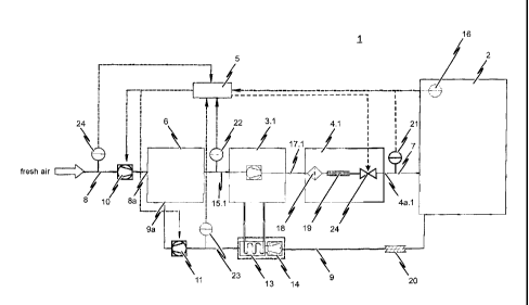
Fig. 1 shows a first exemplary embodiment of an inerting system 1 according to
the present invention in a schematic representation. The inerting system 1
depicted serves to set and maintain a predefinable inerting level in the
spatial
atmosphere of an enclosed room 2. The enclosed room 2 can be a warehouse, for
example, in which the oxygen content of the room's ambient air is lowered to
and
maintained at a specific inerting level of e.g. 12% or 13% by volume of oxygen
as a preventive fire protection measure.
The enclosed room 2 is selectively rendered inert automatically by means of a
control unit 5. To this end, the inerting system 1 according to the embodiment
depicted in Fig. 1 comprises a gas separation system consisting of a
compressor
3.1 as well as a nitrogen generator 4.1. The compressor 3.1 serves to provide
a
compressed initial gas mixture to the nitrogen generator 4.1 comprised of at
least
the components of oxygen and nitrogen. To this end, the outlet of the
compressor 3.1 is connected to the inlet of the nitrogen generator 4.1 by
means
of a line system 17.1 in order to supply the compressed initial gas mixture to
the
nitrogen generator 4.1. It is conceivable for the initial gas mixture at the
outlet of
the compressor 3.1 to be compressed to a pressure of e.g. 7.5 to 9.5 bar and
preferably 8.8 bar.
The nitrogen generator 4.1 comprises at least one membrane module 19, for
example a hollow fiber membrane module, through which the initial gas mixture
provided by the compressor 3.1 ¨ after having passed through an appropriate
filter 18 ¨ is pressed. The different components contained in the initial gas
mixture (in particular oxygen and nitrogen) diffuse through the hollow fiber
membrane of the membrane module 19 within said membrane module 19 at
different rates according to their molecular structure. The gas separation is
thereby based on the known operating principle of nitrogen only percolating
through the hollow fiber membrane very slowly at a low diffusion rate and
thereby concentrating as it passes through the hollow fiber membrane of the
membrane module 19. A nitrogen-enriched gas mixture is thus provided at the
outlet 4a.1 of the nitrogen generator 4.1. This nitrogen-enriched gas mixture
is ¨
as is also the case with the initial gas mixture supplied at the inlet of the
nitrogen
generator 4.1 ¨ in compressed form, wherein passing through the at least one
CA 02797009 2012-10-18
membrane module 19 of the nitrogen generator 4.1 does, however, lead to a
drop in pressure of e.g. 1.5 to 2.5 bar.
Although not explicitly depicted in Fig. 1, the oxygen-rich gas mixture
separated
out in the nitrogen generator 4.1 is concentrated and discharged to the
surroundings at atmospheric pressure.
The nitrogen-enriched gas mixture provided at the outlet 4a.1 of the nitrogen
generator 4.1 is fed to the enclosed room 2 through a supply line 7.1 in order
to
lower the oxygen content in the spatial atmosphere of the enclosed room 2,
respectively to maintain a previously-set drawdown level in room 2, by adding
nitrogen-enriched gas.
A suitable pressure relief can be provided so that the pressure within the
enclosed room 2 does not change when the nitrogenated gas mixture is supplied.
This can be realized for example as independently opening/closing pressure
relief
valves (not shown in Fig. 1). On the other hand, it is however also
conceivable
for the discharged volume of ambient air to be supplied to a mixing chamber 6
via a return line system 9 for the purpose of pressure relief when rendering
room
2 inert.
The ambient air discharged from the enclosed room 2 is supplied to the mixing
chamber 6 via a first inlet 9a of the return line 9. The mixing chamber 6
further
comprises a second inlet 8a which opens into a supply line system 8 for
supplying
fresh air to the mixing chamber 6. The mixing chamber 6 provides the initial
gas
mixture, which has been compressed by compressor 3 and from which at least a
portion of the oxygen is separated off in the gas separation system (nitrogen
generator 4.1). For this reason, the outlet of the mixing chamber 6 is
connected
to the inlet of the compressor 3.1 by an appropriate line system 15.1.
In detail, a first fan mechanism 11 controllable by control unit 5 is provided
in
the return line system 9 and a second fan mechanism 10, likewise controllable
by
control unit 5, is provided in the fresh air supply line system 8. Doing so
thus
ensures that by appropriately actuating the respective fan mechanisms 10, 11,
the amount of fresh air mixed with the ambient air withdrawn from room 2 will
be
selected such that the volume of air withdrawn from room 2 per unit of time is
identical to the volume of nitrogen-enriched gas mixture provided at the
outlet
CA 02797009 2012-10-18
21
4a.1 of the nitrogen generator 4.1 as piped into the spatial atmosphere of the
enclosed room 2 per unit of time.
The inerting system 1 according to the embodiment of the present invention
depicted schematically in Fig. 1 is characterized by the above-cited control
unit 5
being connected to the correspondingly controllable components of the inerting
system 1 and designed so as to automatically control the nitrogen generator
4.1,
the gas separation system respectively, such that the nitrogenated gas mixture
provided at the outlet 4a.1 of the gas separation system has a residual oxygen
content which is dependent on the oxygen content prevailing in the spatial
atmosphere of the enclosed room 2 at that respective moment. In particular,
the nitrogen generator 4.1 of the depicted preferred realization of the
inventive
inerting system 1 is controlled by means of the control unit 5 such that depen-
ding on the oxygen content in the spatial atmosphere of the enclosed room 2 as
measured by means of an oxygen measuring system 16, the nitrogen-enriched
gas mixture will have a residual oxygen content of between 10.00% to 0.01% by
volume, wherein the residual oxygen content of the nitrogen-enriched gas
mixture decreases as the oxygen content in the spatial atmosphere of the
enclosed room 2 decreases.
To this end, the inventive inerting system 1 further comprises, in addition to
the
above-mentioned oxygen measuring system 16 for measuring or determining the
current oxygen content in the spatial atmosphere of the enclosed room 2, a
residual oxygen content measuring system 21 for measuring the residual oxygen
content in the nitrogenated gas mixture provided at the outlet 4a.1 of the
nitrogen generator 4.1, respectively for determining the nitrogen purity of
the
gas mixture provided at the outlet 4a.1 of the nitrogen generator 4.1. Both
measuring systems 16, 21 are correspondingly connected to the control unit 5.
Fig. 2 shows a schematic view of an inerting system 1 according to a second
embodiment of the present invention. The inerting system 1 according to the
second embodiment is particularly suited to setting and maintaining a
predefined
inerting level in an air-conditioned room such as a cold storage room or a
refrigerated warehouse, for example, as economically as possible. The design
and functioning of the inerting system 1 according to the embodiment depicted
in
Fig. 2 substantially corresponds to the design and functioning of the inerting
CA 02797009 2012-10-18
22
system described above with reference to Fig. 1 so that to avoid repetition,
the
following will only address the differences.
To enable the most economic inerting of an air-conditioned room 2 possible, it
is
preferable to provide a heat exchanger system 13 in the return line system 9
between the room 2 and the mixing chamber 6, as depicted in Fig. 2. It is
further
advantageous for the return line system 9 to be at least partly sheathed in an
appropriate thermal insulation 20 ¨ as indicated in Fig. 2 ¨ so as to prevent
freezing of the return line system 9 when the chilled ambient air withdrawn
from
the enclosed room 2 is fed to the heat exchanger system 13 via the return line
system 9 before said air is then piped into the mixing chamber 6. The heat
exchanger system 13 can comprise a booster fan 14 as needed so that the am-
bient air can be withdrawn from the spatial atmosphere of the enclosed room 2
without a drop in pressure.
The heat exchanger system 13 thereby serves to utilize at least a portion of
the
waste heat resulting from the operation of the compressor 3.1 in order to
accordingly warm the cooled ambient air withdrawn from the room. Different
systems are used for the heat exchanger system 13, such as for example a fin
coil heat exchanger which transfers at least a portion of the thermal energy
of
the exhaust air from compressor 3.1 to the air withdrawn from the room by
means of a heat-exchange medium such as e.g. water so as to raise the
temperature of the withdrawn ambient air to a moderate temperature of for
example 20 C, which is advantageous in terms of the functioning and the
efficiency of the nitrogen generator 4.1.
After the ambient air withdrawn from the enclosed room 2 has filtered through
the heat exchanger system 13, it is fed to the mixing chamber 6 via a first
inlet
9a of the return line system 9. The mixing chamber 6 further comprises a
second
inlet 8a, into which a supply line system 8 opens for supplying fresh air to
the
mixing chamber 6. The mixing chamber 6 provides the initial gas mixture,
compressed by compressor 3.1 and from which at least a portion of the oxygen
has been separated off in the gas separation system (nitrogen generator 4.1).
For this reason, the outlet of the mixing chamber 6 is connected to the inlet
of
the compressor 3.1 by means of an appropriate line system 15.
CA 02797009 2012-10-18
23
Fig. 3 shows a schematic view of an inerting system 1 according to a third
embodiment of the present invention. The design and functioning of the
inerting
system 1 according to the embodiment depicted in Fig. 3 substantially
corresponds
to the design and functioning of the inerting system described above with
reference to Fig. 1 so that to avoid repetition, the following will only
address the
differences.
As Fig. 3 shows, the mixing chamber of the embodiment depicted therein is
realized as a filter 6'. The mixing chamber realized as a filter 6' thus
fulfills two
functions: on the one hand, it serves to provide the initial gas mixture, and
does
so by mixing the fresh air supplied by the fresh air supply line system with
the
ambient air withdrawn from room 2 supplied by the return line system 9. On the
other hand, the mixing chamber realized as filter 6' serves to filter the
provided
initial gas mixture prior to it being compressed by means of compressor 3.1.
This
thus dispenses with the need for an additional filter at the inlet of
compressor 3.1.
A fourth exemplary embodiment of the inventive inerting system 1 will be
described below making reference to the representation provided in Fig. 4.
The design and functioning of the inerting system 1 according to the fourth
embodiment is essentially identical to the embodiment described above with
reference to the Fig. 1 depiction, albeit the embodiment according to Fig. 4
makes use of a plurality of nitrogen generators 4.1, 4.2 and 4.3 connected in
parallel. Each nitrogen generator 4.1, 4.2, 4.3 is respectively associated
with a
compressor 3.1, 3.2, 3.3 which is connected to the mixing chamber 6 by means
of a corresponding line system 15.1, 15.2, 15.3 so as to suction off the
necessary
initial gas mixture from the mixing chamber 6 for the associated nitrogen
generator 4.1, 4.2, 4.3 and to compress it to the pressure value required for
the
optimum operation of the respective nitrogen generator 4.1, 4.2, 4.3. Each
nitrogen generator 4.1, 4.2, 4.3 utilized in the inerting system 1 according
to the
embodiment depicted in Fig. 4 is connected to the enclosed room 2 by means of
a corresponding supply line 7.1, 7.2, 7.3. Hence, the gas separation system
depicted in the Fig. 4 embodiment is formed by the "nitrogen generator 4.1,
4.2,
4.3" components and the associated "compressor 3.1, 3.2, 3.3" components.
As with the embodiments of the inventive solution described above with
reference
to the representations provided in Figs. 1 to 3, the embodiment according to
Fig. 4
CA 02797009 2012-10-18
24
also makes use of a return line 9. As depicted, a first fan mechanism 11 is
pro-
vided in the return line 9 which can be correspondingly controlled by the
control
unit 5 such that a portion of the ambient air can be withdrawn from the
enclosed
room 2 in regulated manner and fed to the mixing chamber 6. A fresh air supply
line 8 is further provided in the embodiment depicted in Fig. 4 to supply
fresh air
from an external area 25 to the mixing chamber 6 in regulated manner. To this
end, a second fan mechanism 10 controllable by the control unit 5 is provided
in
the fresh air supply line 8.
As with the embodiments of the inventive inerting system 1 described above, a
mixing chamber 6 is also provided in the embodiment depicted in Fig. 4 in
order
to provide an initial gas mixture comprised of oxygen, nitrogen and other
compo-
nents as applicable. The initial gas mixture provided in the mixing chamber 6
is
supplied to the respective compressors 3.1, 3.2, 3.3 of the gas separation
system
through the corresponding line systems 15.1, 15.2, 15.3.
So that the initial gas mixture provided by the mixing chamber 6 is in an
optimum
state for the respective nitrogen generators 4.1, 4.2, 4.3 employed, the
embodi-
ment of the inventive inerting system 1 depicted in Fig. 4 provides for a
mixing
section 12 to be integrated in the mixing chamber 6, although it is not
mandatory
for said mixing section 12 to be integrated into the mixing chamber 6, it can
also
be provided upstream of the mixing chamber 6.
Specifically, in the embodiment shown in Fig. 4, the return line 9 on the one
hand
and the fresh air supply line 8 on the other open into mixing section 12.
Although
not explicitly shown in Fig. 4, it is hereby preferred for the end 9a of the
return
line 9 and the end 8a of the fresh air supply line 8 to open into mixing
section 12
by means of a Y-connector preferably situated at the upstream end portion of
said mixing section 12.
The mixing section 12 serves in the optimum mixing of the fresh air supplied
through supply line 8 and the room air supplied through return line 9. To this
end, it is preferred for the mixing section 12 to be dimensioned so that a
turbulent
flow will be produced within the mixing section 12. This can for example be
achieved by reducing the effective flow cross section of mixing section 12 so
as to
have a flow rate be set in the mixing section 12 which is greater than the
limiting
velocity to produce a turbulent flow characteristic of and dependent on the
CA 02797009 2012-10-18
corresponding Reynolds number. Alternatively or additionally hereto, it is
equally
conceivable to provide appropriate spoiler elements in the mixing section 12
to
induce a turbulent flow in said mixing section 12.
As can be noted from the schematic representation provided in Fig. 4, the
mixing
section 12 exhibits a length sufficiently long enough to effect the most
optimally
thorough mixing of the fresh and room air supplied from the upstream situated
end portion to the downstream situated end portion of the mixing section.
Experimental tests have shown that it is advantageous for the mixing section
12
to be of a length which is at least five times the effective flow cross
section of
the mixing section 12.
The ambient air return from the enclosed room 2 through return line 9 and
thoroughly mixed with the supplied fresh air in the mixing section 12 is piped
into
the mixing chamber 6 at the downstream end portion of the mixing section 12.
In
contrast to the mixing section 12, the mixing chamber 6 exhibits a clearly
larger
effective flow cross section in order to be able to effect flow abatement. It
is
particularly necessary for the initial gas mixture ultimately provided in the
mixing
chamber 6 to always be in an optimized state for the nitrogen generators 4.1,
4.2,
4.3 employed. This in particular means that the difference between the
pressure
prevailing in the mixing chamber 6 and the external atmospheric pressure does
not exceed a predefined or predefinable upper threshold nor fall short of a
predefined or predefinable lower threshold. In addition, the maximum flow rate
which can occur in the mixing chamber should be less than 0.1 m/s on average.
In order to be able to comply with these conditions in terms of the initial
gas
mixture, the embodiment of the inventive inerting system 1 depicted in Fig. 4
provides for a pressure sensor 26 inside the mixing chamber 6. Said pressure
sensor 26 measures the pressure prevailing inside the mixing chamber 6
continuously or at predetermined times and/or upon predetermined events and
furnishes it to the control unit 5. The control unit 5 compares the pressure
value
measured in the mixing chamber 6 to the pressure value of the external
atmosphere and accordingly regulates the first and/or second fan mechanism 11,
10 based on this comparison of the two pressure values in order to ensure that
the difference between the pressure prevailing in the mixing chamber 6 and the
external atmospheric pressure does not exceed the predefined or predefinable
upper threshold nor fall short of the predefined or predefinable lower
threshold.
CA 02797009 2012-10-18
26
For the sake of completeness, it is pointed out that a corresponding pressure
sensor 27 is provided in the external area 25 to measure the pressure in the
external area 25 continuously or at predetermined times and/or upon
predetermined events and furnish it to the control unit 5. Alternatively, the
pressure sensor 26 could also be a differential pressure sensor.
In the embodiment of the inventive inerting system 1 depicted in Fig. 4, the
control unit 5 is designed so as to control the first fan mechanism 11 and/or
the second fan mechanism 10 such that the difference between the pressure
prevailing in the mixing chamber 6 and the external atmospheric pressure
amounts to a maximum of 0.1 mbar and preferably a maximum of 0.5 mbar.
As can be noted from the Fig. 4 depiction, a total of three nitrogen
generators 4.1,
4.2, 4.3 are used for the purpose of gas separation. It is hereby conceivable
for
some or all of the nitrogen generators 4.1, 4.2, 4.3 to be based on different
gas
separation techniques. It is thus for example conceivable for the first
nitrogen
generator 4.1 to use a separating membrane for the gas separation. The com-
pressor 3.1 associated with the first nitrogen generator 4.1 is then to be
correspon-
dingly adjusted to the applicable pressure to be established at the inlet of
said
nitrogen generator 4.1 (e.g. 13 bar). The second nitrogen generator 4.2 can
then
for example make use of PSA technology for the purpose of the gas separation.
The associated compressor 3.2 is to be accordingly configured in this case,
whereby
it would have to supply an initial pressure of e.g. 8 bar. The further
nitrogen
generator 4.3 utilized in the embodiment according to Fig. 4 can be a nitrogen
generator based, for example, on VPSA technology. The associated compressor
3.3
is then to be configured such that low pressure is provided at its outlet.
Thus, the gas separation system depicted in the Fig. 4 embodiment makes use of
a combination of different nitrogen generators 4.1, 4.2, 4.3, wherein the
compressors 3.1, 3.2, 3.3 respectively associated with the nitrogen generators
4.1, 4.2, 4.3 are adapted to each nitrogen generator's respective operating
mode.
In order to be able to ensure the optimum functioning of the gas separation
system, the mixing chamber 6 needs to be of a large enough design so that no
inadmissible pressure fluctuations will occur during the operation of the
individual
compressors 3.1, 3.2, 3.3 and in particular there will be no interactive
impact on
the nitrogen generators 4.1, 4.2, 4.3 employed. As previously noted, the
CA 02797009 2012-10-18
27
maximum value of permissible pressure fluctuations is preferably 1.0 mbar and
even more preferred is 0.5 mbar.
Although not explicitly depicted in Fig. 4, it is preferred for the respective
line
systems 15.1, 15.2, 15.3 which connect the respective compressors 3.1, 3.2,
3.3
to the mixing chamber 6 to open into the mixing chamber 6 by way of
appropriately dimensioned suction openings so as to be able to prevent any
direct
dynamic influencing of the intake air flow. Similarly, the suction openings
should
be positioned so as to be accordingly distanced from one another.
The use of the special mixing chamber 6, mixing section 12 respectively, as
previously described is not limited to the embodiment of the inventive
inerting
system 1 depicted in Fig. 4. Rather, it is quite conceivable to also use the
mixing
chamber 6, mixing section 12 respectively, from Fig. 4 in the embodiments
shown
in figures 1 to 3 in order to optimize the operation of the inerting system 1.
As with the above-described embodiments of the inventive inerting system, the
inerting system 1 according to the Fig. 4 depiction also provides for
measuring
the oxygen content of the initial gas mixture provided in mixing chamber 6
continuously or at predetermined times and/or upon predetermined events and
feeding the measured value to the control unit 5. It is hereto advantageous
for a
corresponding oxygen sensor 22 to be arranged at the downstream end portion of
the mixing section 12.
Providing an oxygen measuring system in return line 9 is of further advantage.
However, in place of an oxygen measuring system in the return line 9, the
oxygen
content of the ambient air within the enclosed room 2 can also be measured. To
this end, a an oxygen measuring system 16 correspondingly provided in room 2
is
used in the embodiment depicted in Fig. 4.
In the embodiment depicted in Fig. 4, in which a plurality of nitrogen
generators
4.1, 4.2, 4.3 are used for the gas separation, it is preferable to measure the
respective flow rates of the gas flows piped from the respective outlets 4a.1,
4a.2, 4a.3 of the nitrogen generators 4.1, 4.2, 4.3 to the enclosed room 2. As
shown, the corresponding sensors 28.1, 28.2, 28.3 are used in the embodiment
depicted in Fig. 4 for this purpose.
CA 02797009 2012-10-18
28
Of further advantage is measuring the flow rate of the return line 9 by means
of
a volumetric flow sensor 29, the flow rate of the fresh air supply 8 by means
of a
volumetric flow sensor 30 and the flows rates of the initial gas mixtures
supplied
to the individual compressors 3.1, 3.2, 3.3 as applicable. All the measured
values
are fed to control unit 5, which then correspondingly actuates the respective
controllable components of the inerting system 1 so as to keep the pressure
difference between the mixing chamber 6 and the external area 25 within the
permissible control range.
The embodiment depicted in Fig. 4 moreover provides for the control unit 5
being
able to set the residual oxygen content at each nitrogen generator 4.1, 4.2,
4.3.
In a preferred realization of the inerting system 1 depicted schematically in
Fig.
4, 10 to 11 VPSA nitrogen generators and 2 to 4 membrane nitrogen generators
are used in parallel, whereby the mixing chamber has a surface area of 10 m x
4.3 m.
As set forth in detail below with reference being made to the graphical
depictions
according to figures 5 to 7, appropriately setting the nitrogen purity of the
nitrogen generator(s) 4.1, 4.2, 4.3 utilized, respectively appropriately
setting the
residual oxygen content in the nitrogenated gas mixture provided at the
respective
outlet 4a.1, 4a.2, 4a.3 of the gas separation system, enables a predefined
draw-
down level to be set in the spatial atmosphere of the enclosed room in a
manner
which is optimized in terms of the time required. Accordingly, the inventive
solution thereby provides for the nitrogen purity of the nitrogen generator(s)
4.1,
4.2, 4.3 utilized to be set and adjusted as a function of the oxygen content
prevailing in the spatial atmosphere of the enclosed room 2 at that respective
moment when said enclosed room 2 is being rendered inert.
The nitrogen purity can be changed by varying the dwell time of the initial
gas
mixture in the at least one membrane module 19 of the nitrogen generator(s)
4.1, 4.2, 4.3 employed. It is hereby conceivable, for example, to regulate the
flow through the membrane module 19 and the backpressure by means of a
suitable control valve 24 at the outlet of membrane module 19. A high pressure
on the membrane and a long dwell time (lower flow rate) result in a high
nitrogen
purity at the respective outlet 4a.1, 4a.2, 4a.3 of the respectively employed
nitrogen generator 4.1, 4.2, 4.3.
CA 02797009 2012-10-18
29
A time-optimized value is preferably selected for the respective nitrogen
purity
which enables the inerting system to set and maintain a predefined inerting
level
in the enclosed room 2 within the shortest amount of time possible. By making
use of the appropriate time-optimized values for the nitrogen purity when
setting
and maintaining a predefined inerting level in the spatial atmosphere of the
enclosed room, it is possible to reduce the time required for the drawdown
process (whether for maintaining a fixed residual oxygen content or when
lowering to a new drawdown level) and thus also reduce the energy the inerting
system requires since the compressor 3.1, 3.2, 3.3 is digitally driven
(in/out) to
its operating point at optimized efficiency.
The inerting system 1 according to the embodiment depicted in Fig. 1, 2, 3 or
4 is
further characterized by the mixing chamber 6 providing the gas separation
system
consisting of the compressor 3.1 and the nitrogen generator 4.1, the gas
separation
system consisting of compressors 3.1, 3.2, 3.3 and nitrogen generators 4.1,
4.2,
4.3 respectively, with an initial gas mixture which can have a lower oxygen
content
than the oxygen content of normal ambient air (i.e. approx. 21% by volume).
Specifically, the above-cited return line system 9 is provided for this
purpose, same
supplying at least a portion of the ambient air of the enclosed room 2 to the
mixing
chamber 6 through fan mechanism 11 in a manner regulated by control unit 5.
Thus, when the oxygen content has already been reduced in enclosed room 2, the
return line system 9 will supply the mixing chamber 6 with a gas mixture which
is
nitrogen-enriched compared to the normal ambient air. This portion of the
room's
air is mixed with supply air in mixing chamber 6 in order to provide the
compressor
3.1 and the nitrogen generator 4.1, compressors 3.1, 3.2, 3.3 and nitrogen
generators 4.1, 4.2, 4.3 respectively, with the required volume of initial gas
mixture. Since the oxygen content of the initial gas mixture influences the
air factor
of the gas separation system, the nitrogen generators 4.1, 4.2, 4.3 as
employed
respectively, and thus also influences the time-optimized value for the
nitrogen
purity of the nitrogen generators 4.1, 4.2, 4.3 as employed, the embodiment of
the
inventive inerting system 1 depicted in Fig. 1 provides for an oxygen
measuring
system 22 in the line system 15.1 between the outlet of the mixing chamber 6
and
the inlet of the compressor 3.1 to measure the oxygen content in the output
gas
mixture. It is hereto furthermore optionally conceivable to provide
corresponding
oxygen measuring systems 23, 24 in the return line system 9, the fresh air
supply
line 8 respectively, in order to measure the oxygen content in the supply air
and in
CA 02797009 2012-10-18
the nitrogen-enriched room air continuously or at predefined times and/or upon
predefined events. On the basis of the measured readings, the composition of
the
initial gas mixture (in particular in terms of its oxygen content) can be
appropriate-
ly influenced by the appropriate actuating of fan mechanisms 10 and/or 11.
The following will draw reference to the graphical representations provided in
figures 5 to 7 in describing how the inventive solution of the inerting system
1
depicted schematically in figures 1 to 4 functions. With respect to the
inerting
system 1 depicted schematically in figures 1 to 4, the assumption is to be
made
that the enclosed room 2 has a spatial volume of 1000 cubic meters. It is
further
to be assumed that the inerting system 1 is designed so as to provide a
maximum
total of 48 cubic meters nitrogenated gas per hour at the outlet of the gas
separation system.
Fig. 5 represents a graphical depiction of the air factor for the gas
separation
system used in the inerting system 1 schematically depicted in Figs. 1 to 4 at
different nitrogen purities. It is to be accordingly noted that the air factor
increases exponentially as the residual oxygen content of the nitrogen-
enriched
gas mixture provided at the outlet of the gas separation system decreases.
Specifically, the air factor at a residual oxygen content of 10% by volume
(nitrogen purity: 90%) is approximately 1.5, which means that a volume of 0.67
cubic meters of nitrogen-enriched gas mixture can be provided at the outlet of
the gas separation system per cubic meter of initial gas mixture. This ratio
declines with increasing nitrogen purity as can be noted from the Fig. 5
graph.
Fig. 5 additionally depicts the air factor trend according to which the
regulating
drawdown time reacts with increasing nitrogen purity at different nitrogen
purities. It is specifically depicted on the one hand how long the compressor
or
compressors 3.1, 3.2, 3.3 need to run in order to lower the oxygen content in
the
spatial atmosphere of the enclosed room 2 from its original 17.4% by volume to
17.0% by volume. How long the compressor or compressors 3.1, 3.2, 3.3 need to
run in order to lower the oxygen content in the spatial atmosphere of the
enclosed
room 2 from its original 13.4% by volume to 13.0% by volume with the inerting
system 1 according to Figs. 1 to 4 is then also depicted on the other hand.
The comparison of the two drawdown times (drawdown time control of 17.4% ¨>
17.0% by volume and drawdown time control of 13.4% 13.0% by volume)
CA 02797009 2012-10-18
31
shows that to set and maintain an inerting level of 17.0% by volume, the
runtime
of compressor 3.1, compressors 3.1, 3.2, 3.3 respectively, can be minimized
when
a nitrogen purity of approx. 93.3% by volume is set at the gas separation
system.
However, to set and maintain an inerting level of 13% by volume oxygen
content,
the time-optimized purity will then be about 94.1% nitrogen by volume. Hence
the
drawdown time or the runtime of compressor 3.1 or compressors 3.1, 3.2, 3.3
respectively for setting a predefined inerting level in the spatial atmosphere
of
enclosed room 2 is dependent upon the nitrogen purity set for the gas
separation
system, or respectively dependent upon the residual oxygen content of the
nitrogen-enriched gas mixture provided at the outlet of the gas separation
system
as set by means of the nitrogen generators 4.1, 4.2, 4.3 employed.
The respective minima of the drawdown time relative the nitrogen purity is
referred to in the following as "time-optimized nitrogen purity." The Fig. 6
depiction shows the optimized nitrogen purity for the inerting system 1
according
to Figs. 1 to 4. Specifically indicated is the time-optimized purity which
applies to
the gas separation system of the inerting system 1 according to Figs. 1 to 4
for
the different oxygen concentrations in the spatial atmosphere of enclosed room
2.
It can be directly seen from the characteristic curve depicted in Fig. 6 that
the
nitrogen generators 4.1, 4.2, 4.3 employed are to be set such that the
residual
oxygen content in the gas mixture provided at the outlet of the gas separation
system decreases with decreasing oxygen content in the spatial atmosphere of
enclosed room 2. When the employed nitrogen generator is accordingly operated
pursuant the nitrogen purity characteristic curve depicted in Fig. 6 when
rendering enclosed room 2 inert, it is possible to set and maintain the
predefined
inerting level in the spatial atmosphere of enclosed room 2 at the shortest
possible runtime of the compressors 3.1, 3.2, 3.3 as employed and thus at the
lowest possible expenditure of energy.
Fig. 7 provides a graphical depiction of the influence the oxygen content in
the
initial gas mixture has on the gas separation system air factor. According
thereto,
at a fixed nitrogen purity for the gas separation system, the air factor drops
as
the oxygen content is reduced in the initial gas mixture. As noted above, the
return supply line 9 is provided in the inerting system 1 according to the
schematic depiction of e.g. Fig. 1, by means of which a portion of the room's
ambient air (already nitrogenated where applicable) is fed to the mixing
chamber
CA 02797009 2012-10-18
32
6 in regulated manner so as to thus reduce the oxygen content of the initial
gas
mixture from its original 21% by volume (the oxygen content of normal ambient
air). This recirculating of the room's already nitrogenated air can thus
further
reduce the air factor of the gas separation system so that the efficiency of
the
gas separation system will be increased and the energy required to set and
maintain a predefined inerting level can be even further reduced.
The characteristic curve depicted in Fig. 7 can preferably be combined with
the
method graphically represented by Figs. 5 and 6 such that an optimized supply
of
nitrogen is provided for each initial gas mixture oxygen concentration and in
room 2.
Fig. 8 depicts ¨ for a calculated application ¨ the energy savings which can
be
achieved (in %) with the oxygen content set in the spatial atmosphere of an
enclosed room when the inventive solution lowers the oxygen concentration in
the spatial atmosphere of the enclosed room. The case depicted here is one in
which the time-optimized nitrogen purity was selected for the nitrogen
generator's
nitrogen purity during the inerting of the room on the one hand and, on the
other,
the previously nitrogenated room air was recirculated so as to thereby further
reduce the nitrogen generator's air factor and increase its efficiency.
A fifth exemplary embodiment of the inventive inerting system 1 will be
described
in the following with reference being made to the depiction provided in Fig.
9.
The design and functioning of the inerting system 1 according to the fifth
embodiment is essentially identical to that of the fourth embodiment described
above with reference to Fig. 4. The nitrogen generator 4.3 of the plurality of
nitrogen generators 4.1, 4.2. and 4.3 connected in parallel is designed in
this fifth
embodiment as a vacuum pressure swing adsorption generator based on VPSA
technology. As previously described referencing the fourth embodiment
according
to Fig. 4, the vacuum pressure swing adsorption generator 4.3 according to the
fifth embodiment is also connected by means of a line system 17.3 to an
associated compressor 3.3 which in turn has a connection to the mixing chamber
6
via a line system 15.3. An intermediate valve is additionally looped into the
line
system 17.3 between the compressor 3.3 and the vacuum pressure swing
adsorption generator 4.3 which is designed so as to be controllable and has a
connection to the control unit 5 for this purpose. Additionally to the
connection
CA 02797009 2012-10-18
33
made between the mixing chamber 6 and the vacuum pressure swing adsorption
generator 4.3 through a compressor 3.3, a further line system 42 is provided
between the mixing chamber 6 and the generator 4.3. An intermediate valve is
again looped into this additional line system 42 which is likewise designed so
as
to be controllable and has a connection to the control unit 5 for this
purpose.
The control unit 5 itself is designed so as to keep the intermediate valve 40
between the compressor 3.3. and the generator 4.3 in an open position during
adsorption operation of the vacuum pressure swing adsorption generator 4.3 and
to keep the intermediate valve 41 between the mixing chamber 6 and the
generator 4.3 in a closed position during such adsorption operation of the
generator 4.3. During desorption operation of the vacuum pressure swing
adsorption generator 4.3 having at least one inlet, the correspondingly
designed
associated compressor 3.3. creates a negative pressure at the at least one
inlet
of the generator 4.3; i.e. a pressure which is reduced to approaching vacuum
compared to the ambient pressure. During this desorption phase, the control
unit
then opens the intermediate valve 41 between the mixing chamber 6 and the
generator 4.3, preferably a few seconds, and particularly preferred five
seconds,
prior to the scheduled end of the desorption phase so that nitrogen-enriched
air
can flow though the line system 42 directly from the mixing chamber 6 into the
at
least inlet of the vacuum pressure swing adsorption generator 4.3 before the
desorption phase ends. To prevent an obstructing of the influx and interaction
with the compressor 3.3, it can then be provided for the intermediate valve 40
between the compressor 3.3 and the generator 4.3 to be brought into a closed
position during this pressure equalization process. The passive influx of the
nitrogen-enriched air from the mixing chamber into the at least one inlet of
the
generator 4.3; i.e. not induced by the associated compressor 3.3, then
undergoes
an increase in pressure prior to the end of the desorption phase at the inlet
and
within the generator 4.3 to no more than the pressure inside the mixing
chamber
6, which occurs relatively rapidly due to bypassing the compressor 3.3 and
moreover does not require any energy-intensive operation of the associated
compressor 3.3 during said pressure equalization process.
In a subsequent adsorption phase of the vacuum pressure swing adsorption
generator 4.3, the associated compressor 3.3 can then bring the generator 4.3
to
its operating pressure in a shorter amount of time, whereby the adsorption and
thus the providing of nitrogenated air in turn commences earlier. Because the
air
CA 02797009 2012-10-18
34
from mixing chamber 6 used in the pressure equalization is already
nitrogenated,
the oxygen level in the subsequent adsorption phase of the generator 4.3
starts
out lower.
The vacuum pressure swing adsorption generator 4.3 is hereby not limited to
one
inlet, one single molecular sieve bed respectively, equipped as applicable
with a
container containing carbon granule. It is instead also conceivable to provide
a
separate controllable intermediate valve 41 in front of each container,
respectively
in front of each inlet of the vacuum pressure swing adsorption generator 4.3;
i.e.
a branching of the line system 42 between the mixing chamber 6 and the
generator 4.3 prior to the respective inlets. This thereby enables the
alternating
adsorption/desorption operation of a vacuum pressure swing adsorption
generator
4.3 so that the most continuous flow of nitrogen-enriched air possible will be
provided at its inlet 4a.3 for feeding into the enclosed room 2.
The mixing chamber 6 is preferably designed as a comparatively long mixing
tube
and the outgoing line systems 15.1, 15.2, 15.3 toward the compressors 3.1,
3.2,
3.3 then branch off from the end of such a mixing tube. The appropriate
dimensioning of a mixing chamber 6, in particular such a relatively long
mixing
tube, then ensures an operation which is largely non-interacting even when
this
type of a passive pressure equalization process uses an additional line system
42
between the mixing chamber 6 and the vacuum pressure swing adsorption
generator 4.3. In other words, the appropriate dimensioning of such a mixing
chamber 6 configured as a long mixing tube reduces the pressure influence;
i.e.
the pressure effect on the nitrogen generators 4.1, 4.2, to a harmless value,
even
when using a vacuum pressure swing adsorption generator 4.3 equipped with a
bypass line 42.
In contrast to this fifth embodiment depicted in Fig. 9, such an additional
line 42
between the mixing chamber 6 and a vacuum pressure swing adsorption generator
4.3 through the intermediary connection of a correspondingly controllable
interme-
diate valve 41 can then however also be an advantage in the absence of a great
plurality of gas separation systems 3.1, 4.1; 3.2, 4.2; 3.3, 4.3 or when
nitrogen
generators 4.1, 4.2, 4.3 utilizing different gas separation techniques are not
employed. Even just providing one vacuum pressure swing adsorption generator
4.3 yields the advantage that, given the appropriate dimensioning of the
mixing
chamber 6, the passive pressure equalization can be regulated by the
intermediate
CA 02797009 2012-10-18
valve 41 prior to the end of the desorption phase of the vacuum pressure swing
adsorption generator 4.3 allows the associated compressor 3.3 to be operated
for
a shorter amount of time in total, thereby providing an energy-saving effect.
A sixth exemplary embodiment of the inventive inerting system 1 will be
described
in the following with reference being made to the depiction provided in Fig.
10.
The design and functioning of the inerting system 1 according to the sixth
embodiment is essentially comparable to the fifth embodiment described above
with reference to the Fig. 9 depiction. As in the above-described fifth embodi-
ment, the nitrogen generator 4.3 of the plurality of nitrogen generators 4.1,
4.2
and 4.3 connected in parallel is likewise configured in this sixth embodiment
as a
vacuum pressure swing adsorption generator based on VPSA technology. The
vacuum pressure swing adsorption generator 4.3 in accordance with the sixth
embodiment is also connected by means of a line system 17.3 to an associated
compressor 3.3 which in turn has a connection to the mixing chamber 6 via line
system 15.3. The vacuum pressure swing adsorption generator 4.3 further
exhibits
an additional inlet directly connected to the mixing chamber 6 by way of an
additional line system 42. The nitrogen generator 4.3 configured as a vacuum
pressure swing adsorption generator additionally comprises two independently
operable adsorption beds 45a and 45b which are connected by way of a
respective
controllable intermediate valve 44a / 44b to an inlet 4a.3 of the nitrogen
generator 4.3 which in turn can supply the enclosed room 2 with nitrogen-
enriched air through a supply line 7.3. A plurality of additional intermediate
valves
40a, 41a, 43a, respectively 40b, 41b, 43b, are provided for each of the
molecular
sieve beds 45a / 45b in the area of the respective molecular sieve bed inlets.
All of
these intermediate valves are designed to be controllable and can be
correspondingly actuated together with the additional intermediate valves 44a,
44b such that the first molecular sieve bed 45a is operated in an adsorption
mode
during a first respective time period so as to supply the supply line 7.3 with
nitrogenated air. During a second period, the second molecular sieve bed 45b
is
then operated in such an adsorption state as to likewise supply the supply
line 7.3
with nitrogenated air. In other words, by means of the respectively
alternating
adsorption/desorption operation of the molecular sieve beds 45a, 45b, a vacuum
pressure swing adsorption generator 4.3 designed as such enables a continuous
flow of nitrogenated air output in the supply line 7.3.
CA 02797009 2012-10-18
36
During the adsorption operation of the first molecular sieve bed 45a of the
vacuum pressure swing adsorption generator 4.3, the intermediate valve 40a
between the inlet of the nitrogen generator 4.3 connected to the compressor
3.3.
by means of line system 17.3 as well as the associated intermediate valve 44a
which regulates the outlet are opened so that nitrogenated air is provided at
the
outlet 4a.3 of the nitrogen generator 4.3. Intermediate valve 40b is
accordingly
closed during such adsorption operation of the first molecular sieve bed 45a
of the
nitrogen generator 4.3 in order to not subject the second molecular sieve bed
45b
to compressed air from the compressor 3.3. The second molecular sieve bed 45b
is operated in desorption mode during this time, with the intermediate valve
43b
being open so as to connect the second molecular sieve bed 45b to the vacuum
source V. Intermediate valves 43a and 44b are accordingly closed in this
operating
mode. Likewise closed are intermediate valves 41a and 41b which can establish
a
connection to the further line system 42 and thus to mixing chamber 6.
If the nitrogen generator 4.3 configured as a pressure swing adsorption
generator is now switched from this operating mode; i.e. from the operating
mode in which the first molecular sieve bed 45a is operated in adsorption mode
and the second molecular sieve bed 45b is operated in desorption mode, to a
reversed operating mode in which the first molecular sieve bed 45a is operated
in
desorption mode and the second molecular sieve bed 45b is operated in
adsorption mode, then shortly before the point in time at which the desorption
mode of the second molecular sieve bed 45b is to be ended, the intermediate
valves 40a, 40b and 43a, 43b as well as the intermediate valves 44a, 44b
arranged as applicable on the outlet side, are closed. At the same time or
directly
thereafter, intermediate valve 41b is then opened in order to create a direct
connection between the mixing chamber 6 and the second molecular sieve bed
45b via the additional line system 42. This results in a passive equalizing of
the
pressure prevailing within the second molecular sieve bed 45b, whereby air
which
is already nitrogenated passively flows from the mixing chamber 6 to the
second
molecular sieve bed 45b in advantageous manner. After the pressure has been
equalized, intermediate valve 41b can be closed again and intermediate valve
40b
opened to connect the compressor 3.3 to the inlet of the second molecular
sieve
bed 45b to initiate the adsorption phase in the second molecular sieve bed
45b.
In corresponding manner, the outlet-side intermediate valve 44b to provide
nitrogenated air at the outlet 4a.3 of the nitrogen generator is opened. At
this
point, the first molecular sieve bed 45a can operate in desorption mode, with
CA 02797009 2012-10-18
37
only the intermediate valve 43a, which connects the inlet of the first
molecular
sieve bed 45a to the vacuum source, needing to be open.
In similar manner, switching this nitrogen generator 4.3 operating with two
molecular sieve beds from an operating mode in which the first molecular sieve
bed 45a is in desorption mode and the second molecular sieve bed 45b is in
adsorption mode with the intermediary step of passive pressure equalization
occurring to end the desorption phase in the first molecular sieve bed 45a.
The invention is not limited to the embodiments shown by way of the represen-
tations provided in the accompany drawings but instead yields from a synopsis
of
all the features disclosed herein. In conjunction hereto, it is in particular
to be
noted that the drawings do not provide a detailed depiction of obvious
features
which are not essential to the invention. For instance, the drawings do not
show
the outlet for the oxygenated gas of the respective nitrogen generators 4.1,
4.2,
4.3. Providing a correspondingly designed control unit 5 and appropriately con-
necting it to the individually controllable elements such as e.g. the
intermediate
valves can likewise be provided in the sixth embodiment according to Fig. 10.
CA 02797009 2012-10-18
38
List of reference numerals
1 inerting system
2 enclosed room
3.1, 3.2, 3.3 compressor
4.1, 4.2, 4.3 nitrogen generator
4a.1, 4a.2, 4a.3 nitrogen generator outlet
control unit
6 mixing chamber
7.1, 7.2, 7.3 supply line
8 (fresh air) supply line
8a fresh air supply line inlet
9 return line
9a return line inlet
second fan mechanism
11 first fan mechanism
12 mixing section
13 heat exchanger system
14 booster fan
15.1, 15.2, 15.3 line system between mixing chamber and compressor
16 oxygen measuring system
17.1, 17.2, 17.3 line system between compressor and nitrogen generator
18 filter
19 membrane module
thermal insulation
21 residual oxygen content measuring system
23 oxygen measuring system in return line 9
24 oxygen measuring system in supply line 8
external area
26 pressure sensor in mixing chamber
27 pressure sensor in external area
28.1, 28.2, 28.3 volumetric flow sensor in supply line 7.1, 7.2, 7.3
29 volumetric flow sensor in return line 9
volumetric flow sensor in fresh air supply line 8
40, 40a, 40b intermediate valve between compressor and
molecular sieve bed inlet
CA 02797009 2012-10-18
39
41, 41a, 41b intermediate valve between mixing chamber and
molecular sieve bed inlet
42 line system between mixing chamber and
nitrogen generator
43a, 43b intermediate valve between vacuum source and
molecular sieve bed inlet
44a, 44b intermediate valve between molecular sieve bed outlet and
supply line
45a, 45b molecular sieve bed and vacuum source V