Note: Descriptions are shown in the official language in which they were submitted.
STRUCTURE FOR FOR CREATING HOUSINGS FOR SETTING TREES INTO THE
GROUND, AND METHOD FOR SETTING TREES INTO THE GROUND.
The present invention relates to a structure for creating
housings for setting trees into the ground and to a method for
setting trees into the ground.
In particular, the present invention relates to a structure for
creating housings for setting trees into road surfaces such as,
for example, pavements, squares, boulevards, which are
generally covered with asphalt or concrete, and which generally
do not show any opencast soil, which is necessary for planting
a tree.
Trees are normally planted into road surfaces by making a hole
or an opening in the road surface itself, so as to remove the
road surface material and gain access to the underlying soil,
into which the roots of the tree will then be placed.
Everything is then covered again by restoring the road surface,
possibly leaving uncovered a circular area around the trunk of
the tree, where the soil will remain visible. In drivable
places, this area is often very small and insufficient to ensure
proper tree vitality. In addition, as the tree grows, the roots
will cause cracks in the covered areas and waves on the road
surface, which may even hinder the practicability of the areas
near the tree.
The object of the present invention is to overcome such
drawbacks by providing a structure for creating housings for
setting trees into the ground, which can create an underground
CA 2797478 2019-01-25
=
- 2 -
region that can be filled with soil, where tree roots will be
able to grow freely. Notwithstanding this, said region is then
covered again to form the road or pavement surface, while at
the same time preserving an underground vital space for the
nourishment and expansion of the roots of the tree. Furthermore,
this substantially prevents the roots from breaking or damaging
the road surface.
Patent IT1288881 filed in the name of the same Applicant
describes a modular floor support and aeration element to be
applied for the purpose of insulating floors from the underlying
soil. Said modular element has an upper face and support legs.
Such elements can be coupled to one another to create a
continuous structure, i.e. a plane onto which a concrete layer
is then cast. Underneath the upper face, a free space is
maintained between the legs where air is allowed to circulate,
thus contributing to preventing moisture from penetrating into
the floor that will then be laid onto the concrete layer.
The Applicant has perceived that such modular elements and other
elements of the same kind described in patents IT1292348 and
IT1379439 can be used for creating a housing under a road
surface, into which soil and other materials suitable for
planting trees can be placed.
One aspect of the present invention relates to a structure for
creating a housing for setting a tree into the ground,
comprising:
tubular extensions, each one of said tubular extensions
having a length and an upper mouth;
CA 2797478 2019-01-25
-3-
a framework for holding in position said tubular
extensions, said framework comprising supports, each
support being adapted to be engageable with a corresponding
one of said upper mouth;
a plurality of modular elements associable one with another
to obtain a substantially continuous upper surface and a
lower volume having a depth corresponding to said length
of said tubular extensions, a portion of said lower volume
being fillable with loam soil or with an appropriate
material for the nourishment of said tree and another
portion of said lower volume remaining at least partially
empty thereby defining said housing, each one of said
plurality of modular elements comprising:
an upper face; and
support legs, each one being insertable into a
corresponding one of said tubular extensions; and
the substantially continuous upper surface being provided
with a through opening located in a position corresponding
to said housing to establish a communication between said
lower volume and an area located above said upper surface,
said through opening being sized and shaped to allow
inserting a lower portion of a trunk of said tree
therethrough,
wherein a portion of said substantially continuous upper
surface is for receiving a reconstructed roadway thereon,
CA 2797478 2019-01-25
-4-
said portion being provided in zones other than said
position of said opening.
A further aspect of the present invention relates to a A method
for setting a tree, shrub, plant or the like into a road surface,
comprising:
forming a lower setting plane having a width;
positioning a plurality of tubular extensions on said lower
setting plane;
forming a framework provided with supports adapted to be
inserted into an upper mouth of said tubular extensions to
hold said extensions in a predetermined position, a filling
volume being created under said framework;
filling said filling volume with loam soil or with a
desired material, except for at least one housing for the
roots of at least one tree;
removing the framework and positioning a plurality of
modular elements, each one comprising an upper face and
support legs, adjacent to one another, by inserting each
leg into said extensions to obtain a substantially
continuous upper surface;
casting concrete or any other material adapted to restore
the road surface;
creating an opening in the upper surface, in a position
corresponding to said housing, for inserting the lower part
CA 2797478 2019-01-25
-5-
of the trunk of the tree; and
positioning the tree by inserting it into said opening.
The features and advantages of the structure according to the
present invention will become more apparent from the following
explanatory and non-limiting description of one embodiment
thereof with reference to the annexed drawings, wherein:
= Figure 1 shows a sectional side view of the structure
according to a first embodiment of the present invention;
= Figure 2 shows a plan view of the structure of Figure 1,
before the support concrete is cast onto it and the road
surface is restored;
= Figure 3 shows a framework which is formed prior to laying
the modular elements of the structure according to an
embodiment of the present invention;
= Figure 4 shows an element of the framework of Figure 3
according to an embodiment of the present invention;
= Figures 5a and 5b show a framework element according to a
further embodiment of the present invention;
= Figure 6 shows a framework obtained by using the elements
of Figures 5a and 5b;
= Figures 7a - 7c show a detail of the coupling between the
tubular extensions and the framework elements.
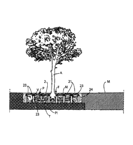
With reference to the above-mentioned drawings, the structure
according to the present invention comprises a plurality of
modular elements 2, each one comprising an upper face 21 and
CA 2797478 2019-01-25
- 6 -
support legs 22. Said elements are associable with one another
to obtain a (flat or arched) surface P, which is substantially
continuous, and an empty lower volume V. Said upper face is
preferably square or rectangular, but it may have a different
shape so long as it is suitable for creating said surface P.
Said element may, for example, be made of plastic, expanded
plastic, wood, reinforced concrete or iron.
Legs 22 are preferably so shaped as to be coupled to the legs
of the adjacent modular element in the structure.
In a central portion of the structure, the absence of at least
one element 2 or a part thereof determines the creation of a
through opening F, which establishes a communication between
volume V and the area above surface P. Through said opening,
the trunk of tree A can be inserted. Volume V is filled with
loam soil or another compatible material suited for the
nourishment and growth of the tree.
On surface P, it is possible to reconstruct road surface M. In
addition, according to a feature of the present invention, the
structure may comprise a plurality of holes 23, obtained above
the modular elements and creating a draining slab, thus allowing
water to pass through the reconstructed road surface and reach
the underlying loam soil.
The modular elements are provided with tubular extensions 24,
which at least partially cover legs 22, which, according to
their length, determine the depth of the housing and hence the
dimension of volume V.
Concrete or another suitable material can be inserted into the
CA 2797478 2019-01-25
-7-
extensions, so as to firmly constrain the legs of adjacent
modular elements 2 to each other. Also, said tubular extensions
filled with material form "small pillars" that determine the
load-carrying capacity of the structure, which must be able to
withstand the weight of the road surface and of anything that
may pass on it.
Such tubular extensions are inserted into the excavation before
modular elements 2. They are held in the operating position
(i.e. substantially vertical) by a framework made up of frame
elements which, in the embodiment of the invention shown in
Figures 3 and 4, are square or rectangular framework frames 3
arranged adjacent to one another, substantially in a chessboard
fashion. The frames rest on the upper ends of the tubular
extensions, thereby holding the latter in the predetermined
position.
The dimensions of said frames match the size of upper face 21
of modules 2.
Said framework frames 3 essentially comprise a quadrangular
crown 31 having at each angle a support 32 adapted to be inserted
into the upper mouth of said tubular extensions. The shape of
said support 32 is such as to facilitate its insertion into the
tubular element, even when there are four associated supports
as shown in Figure 4. In fact, in the embodiment shown in
Figures 3 and 4, the supports consist of 90 circular sectors,
so as to obtain a cylindrical solid when four frame are joined
together in a square arrangement. Said cylindrical solid is
adequately sized to be easily inserted into the tubular
CA 2797478 2019-01-25
-8-
extension, while also acting as a plug for the upper opening of
the extension. In a further embodiment, the tubular extension
may have a quadrangular cross-section.
According to the embodiment shown in Figures 5 and 6, the
framework elements have a substantially cross-shaped structure,
wherein supports 32' are associated with said tubular extensions
and with respective limbs 33 and 34 of said cross. Said limbs
are provided with constraining means 35 for creating a
constraint to the limbs of a similar cross, so as to form a
framework like the one shown in Figure 6.
In other embodiments, the framework is made up of cross-shaped
or quadrangular-frame structures, wherein the supports to be
associated with the tubular extensions are hooks. Said hooks
may be of the type that engages in a "U" fashion into the upper
tubular wall. The upper opening of tubular extensions 24 may
be, without distinction, either closed or left open by the frame
according to the present invention.
Furthermore, each support may have additional grooves, seats
and protuberances adapted to facilitate the engagement between
the frames and the tubular extensions.
After the extensions and the frameworks have been laid, the
excavation is filled with soil and then modules 2 are laid.
Once modules 2 have been laid in position, concrete is cast
which, when hardened, will support road surface M.
The method for setting a tree into the ground is carried out as
follows.
The first step comprises forming a lower setting plane PI, e.g.
CA 2797478 2019-01-25
-9-
by making a sufficiently large excavation.
Subsequently, the tubular extensions are positioned and the
framework is constructed thereon by positioning crowns 3. Once
the extensions have been secured, the excavation can be filled
with loam soil T or with the desired material.
After the excavation has been filled, the framework can be
removed and replaced with modular elements 2.
On said modular elements, concrete or any other material
suitable for supporting the road surface is then cast.
Advantageously, the step of laying the modular elements includes
creating the opening for inserting the trunk of the tree.
This can be achieved through the absence of at least one element
in the desired position, in the area corresponding to the
aforementioned root housing, or by subsequently removing, e.g.
by breaking or coring upper plane 21, at least one of the
already positioned elements and removing the concrete.
The tree is then positioned by inserting it through said
opening.
By so doing, it is possible to restore the road surface very
quickly, in that both the filling of volume V and the
positioning of the tree can be done at a later time, even after
having formed the housing. While the road surface can be
restored immediately after having made the excavation, laid the
modules and cast the concrete.
As an alternative, the tree may be inserted into the excavation
prior to laying the modules, after having removed the framework
and filled the setting plane with soil.
CA 2797478 2019-01-25
=
-10-
According to a further alternative, the excavation is made
around an existing tree, by excavating between the roots and
cutting them as necessary, in order to be able to position
tubular elements 24 and lay the modular elements.
Volume V has suitable dimensions for ensuring a proper
nourishment of the tree and, depending on the type of plant to
be set into the ground, one can choose the number and
composition of the modular elements to be positioned (e.g. to
form a square or a rectangle). In addition, one can change the
length of tubular extensions 24 according to the required height
to be filled with loam soil or another suitable material.
The setting plane may be laterally delimited, in order to
prevent the concrete from entering empty volume V that must be
filled with loam soil, by using known closing elements (not
shown), such as wooden or plastic panels, etc. One suitable
closing element is described in patent US 6,941,705.
CA 2797478 2019-01-25