Note: Descriptions are shown in the official language in which they were submitted.
CA 02797618 2012-10-25
WO 2011/139760 PCT/US2011/034125
- 1 -
METHODS OF FORMING POLYCRYSTALLINE COMPACTS
PRIORITY CLAIM
This application claims the benefit of U.S. Provisional Patent Application
Serial No. 61/328,434, filed April 27, 2010, for "Methods of Removing a
Catalyst
From Polycrystalline Compacts, Methods of Forming Cutting Elements Including
Such
Compacts and Earth-Boring Tools Including Such Compacts."
TECHNICAL FIELD
Embodiments of the present disclosure generally relate to methods of forming
such polycrystalline diamond compact cutting elements for earth-boring tools.
BACKGROUND
Earth-boring tools for forming wellbores in subterranean earth formations
generally include a plurality of cutting elements secured to a body. For
example,
fixed-cutter earth-boring rotary drill bits (also referred to as "drag bits")
include a
plurality of cutting elements that are fixedly attached to a bit body of the
drill bit.
Similarly, roller cone earth-boring rotary drill bits may include cones that
are
mounted on bearing pins extending from legs of a bit body such that each cone
is
capable of rotating about the bearing pin on which it is mounted. A plurality
of
cutting elements may be mounted to each cone of the drill bit. In other words,
earth-boring tools typically include a bit body to which cutting elements are
attached.
The cutting elements used in such earth-boring tools often include
polycrystalline diamond compacts (often referred to as "polycrystalline
diamond
compact"), which act as cutting faces of a polycrystalline diamond material.
Polycrystalline diamond material is material that includes inter-bonded grains
or
crystals of diamond material. In other words, polycrystalline diamond material
includes direct, inter-granular bonds between the gains or crystals of diamond
material. The terms "grain" and "crystal" are used synonymously and
interchangeably herein.
CA 02797618 2012-10-25
WO 2011/139760 PCT/US2011/034125
- 2 -
Polycrystalline diamond compact cutting elements are typically formed by
sintering and bonding together relatively small diamond grains under
conditions of
high temperature and high pressure in the presence of a catalyst (e.g.,
cobalt, iron,
nickel, or alloys and mixtures thereof) to form a layer (e.g., a compact or
"table") of
polycrystalline diamond material on a cutting element substrate. These
processes
are often referred to as high temperature/high pressure (HTHP) processes. The
cutting element substrate may comprise a cermet material (i.e., a ceramic-
metal
composite material) such as, for example, cobalt-cemented tungsten carbide. In
such instances, the cobalt (or other catalyst material) in the cutting element
substrate
may be swept into the diamond grains during sintering and serve as the
catalyst
material for forming the inter-granular diamond-to-diamond bonds, and the
resulting
diamond table, from the diamond grains. In other methods, powdered catalyst
material may be mixed with the diamond grains prior to sintering the grains
together
in an HTHP process.
Upon formation of a diamond table using an HTHP process, catalyst material
may remain in interstitial spaces between the grains of diamond in the
resulting
polycrystalline diamond compact. The presence of the catalyst material in the
diamond table may contribute to thermal damage in the diamond table when the
cutting element is heated during use, due to friction at the contact point
between the
cutting element and the folination.
Polycrystalline diamond compact cutting elements in which the catalyst
material remains in the polycrystalline diamond compact are generally
thermally
stable up to a temperature in a range of about from about seven hundred fifty
degrees Celsius (750 C), although internal stress within the cutting element
may
begin to develop at temperatures exceeding about three hundred fifty degrees
Celsius (350 C). This internal stress is at least partially due to differences
in the
rates of thermal expansion between the diamond table and the cutting element
substrate to which it is bonded. This differential in thermal expansion rates
may
result in relatively large compressive and tensile stresses at the interface
between the
diamond table and the substrate, and may cause the diamond table to delaminate
from the substrate. At temperatures of about seven hundred fifty degrees
Celsius
(750 C) and above, stresses within the diamond table itself may increase
CA 02797618 2012-10-25
WO 2011/139760 PCT/US2011/034125
- 3 -
significantly due to differences in the coefficients of thermal expansion of
the
diamond material and the catalyst material within the diamond table. For
example,
cobalt thermally expands significantly faster than diamond, which may cause
cracks
to foini and propagate within the diamond table, eventually leading to
deterioration
of the diamond table and ineffectiveness of the cutting element.
Furthermore, at temperatures at or above about seven hundred fifty degrees
Celsius (750 C), some of the diamond crystals within the polycrystalline
diamond
compact may react with the catalyst material causing the diamond crystals to
undergo a chemical breakdown or back-conversion to another allotrope of carbon
or
another carbon-based material. For example, the diamond crystals may
graphitize at
the diamond crystal boundaries, which may substantially weaken the diamond
table.
In addition, at extremely high temperatures, in addition to graphite, some of
the
diamond crystals may be converted to carbon monoxide and carbon dioxide.
In order to reduce the problems associated with differential rates of thermal
expansion and chemical breakdown of the diamond crystals in polycrystalline
diamond compact PDC cutting elements, so-called "theunally stable"
polycrystalline
diamond compacts (which are also known as thermally stable products, or
"TSPs")
have been developed. Such a thermally stable polycrystalline diamond compact
may be formed by leaching the catalyst material (e.g., cobalt) out from
interstitial
spaces between the inter-bonded diamond crystals in the diamond table using,
for
example, an acid or combination of acids (e.g., aqua regia). Thermally stable
polycrystalline diamond compacts in which substantially all catalyst material
has
been leached out from the diamond table have been reported to be thermally
stable
up to temperatures of about twelve hundred degrees Celsius (1200 C).
Examples of conventional acid leaching processes are described in U.S.
Patent No. 6,410,085 to Griffin et al. (issued June 25, 2002), U.S. Patent No.
6,435,058 to Matthias et al. (issued August 20, 2002), U.S. Patent No.
6,481,511 to
Matthias et al. (issued November 19, 2002), U.S. Patent No. 6,544,308 to
Griffin et
al. (issued April 8, 2003), U.S. Patent No. 6,562,462 to Griffin et al.
(issued May 13,
2003), U.S. Patent No. 6,585,064 to Griffin et al. (issued July 1, 2003), U.S.
Patent
No. 6,589,640 to Griffin et al. (issued July 8, 2003), U.S. Patent No.
6,592,985 to
Griffin et al. (issued July 15, 2003), U.S. Patent No. 6,601,662 to Matthias
et al.
CA 02797618 2012-10-25
WO 2011/139760 PCT/US2011/034125
- 4 -
(issued August 5, 2003), U.S. Patent No. 6,739,214 to Matthias et al. (issued
May 25, 2004), U.S. Patent No. 6,749,033 to Matthias et al. (issued June 15,
2004) =
and U.S. Patent No. 6,797,326 to Matthias et al. (issued September 28, 2004).
However, such acid leaching processes are problematic because the acid
compounds
used therein are difficult to control in use, problematic to store, require
prolonged
exposure times under elevated temperature and, in addition, generate a
substantial
quantity of hazardous waste.
Furtheunore, conventional acid leaching processes often result in
non-unifoini removal of the catalyst material caused by the aggressive action
of the
acid compounds on polycrystalline material of the polycrystalline diamond
compacts. Such non-uniform removal may compromise durability and reduce
temperature tolerance of the polycrystalline diamond compacts having the
catalyst
material removed from only a portion thereof. For example, removal of catalyst
material using conventional acid leaching processes may results in spikes,
valleys
and variations that extend beyond a depth of the polycrystalline diamond
compact to
which removal of the catalyst material is desired.
DISCLOSURE
In some embodiments, the present disclosure includes methods of forming a
polycrystalline compact for use in an earth-boring tool. Such methods may
include at
least partially melting at least one of a silicate glass, an alkali metal
salt, and a rare
earth element to foiin a reactive material and introducing the reactive
material to a
polycrystalline compact comprising a catalyst material disposed in
interstitial spaces
between inter-bonded crystals of a polycrystalline material to remove at least
a portion
of the catalyst material.
In additional embodiments, the present disclosure includes methods of forming
a polycrystalline compact cutting element for an earth-boring tool. Such
methods may
include forming a cutting element comprising a polycrystalline material and a
catalyst
material disposed in interstitial spaces between inter-bonded crystals of the
polycrystalline material and removing at least a portion of the catalyst
material from
the interstitial spaces by exposing at least a portion of the polycrystalline
material to at
CA 02797618 2015-03-19
- 5 -
least one of a solution comprising acetic acid and a chemical plasma
comprising an
inert gas or an oxidizing agent.
In accordance with an aspect of the present invention there is provided a
method of forming a polycrystalline compact for use in an earth boring tool,
comprising:
at least partially melting at least one of a silicate glass, an alkali metal
salt,
and a rare earth element to form a reactive material;
introducing the reactive material to a polycrystalline compact comprising a
plurality of interstitial spaces between inter bonded crystals of a
polycrystalline
material throughout which interstitial spaces a catalyst material is
dispersed; and
removing at least a portion of the catalyst material with the reactive
material
from at least a portion of the plurality of interstitial spaces.
In accordance with a further aspect of the present invention there is provided
a
method of forming a polycrystalline compact for use in an earth boring tool,
comprising:
at least partially melting a rare earth element to form a reactive material;
and
introducing the reactive material to a polycrystalline compact comprising a
catalyst material disposed in interstitial spaces between inter bonded
crystals of a
polycrystalline material to remove at least a portion of the catalyst
material, wherein
at least partially melting at least one of a silicate glass, an alkali metal
salt, and a rare
earth element to form a reactive material comprises at least partially melting
a
plurality of rare earth elements to form a binary eutectic liquid.
In accordance with a further aspect of the present invention there is provided
a
method of forming a polycrystalline compact cutting element for an earth-
boring tool,
comprising:
forming a cutting element comprising a polycrystalline material and a catalyst
material disposed in interstitial spaces between inter bonded crystals of the
polycrystalline material; and
removing at least a portion of the catalyst material from the interstitial
spaces
by exposing at least a portion of the polycrystalline material to a solution
comprising
acetic acid, wherein removing at least a portion of the catalyst material from
the
interstitial spaces by exposing at least a portion of the polycrystalline
material to a
solution comprising acetic acid comprises:
CA 02797618 2014-05-27
- 5a -
introducing the at least a portion of the polycrystalline material to a
solution
of the acetic acid and water; and
adding at least one of an oxalic acid and an oxalic acid ester to the
solution.
In accordance with a further aspect of the present invention there is provided
a
method of forming a polycrystalline compact cutting element for an earth
boring tool,
comprising:
forming a cutting element comprising a polycrystalline material and a catalyst
material disposed in interstitial spaces between inter bonded crystals of the
polycrystalline material; and
removing at least a portion of the catalyst material from the interstitial
spaces
by exposing at least a portion of the polycrystalline material to a solution
comprising
acetic acid, wherein removing at least a portion of the catalyst material from
the
interstitial spaces by exposing at least a portion of the polycrystalline
material to a
solution comprising acetic acid comprises:
oxidizing a xylene in the presence of the acetic acid to form the solution;
introducing the solution to the at least a portion of the polycrystalline
material
to dissolve the catalyst material.
In accordance with a further aspect of the present invention there is
providedA
method of forming a polycrystalline compact cutting element for an earth
boring tool,
comprising:
forming a cutting element comprising a polycrystalline material and a catalyst
material disposed in interstitial spaces between inter bonded crystals of the
polycrystalline material; and
removing at least a portion of the catalyst material from the interstitial
spaces
by exposing at least a portion of the polycrystalline material to a chemical
plasma
comprising an inert gas or an oxidizing agent, wherein removing at least a
portion of
the catalyst material from the interstitial spaces by exposing at least a
portion of the
polycrystalline material to a chemical plasma comprises introducing at least
one
surface of the polycrystalline material to a chemical plasma comprising at
least one of
argon, nitrogen, helium, xenon, krypton, and radon.
In accordance with a further aspect of the present invention there is
providedA
method of forming a polycrystalline compact cutting element for an earth
boring tool,
comprising:
CA 02797618 2014-05-27
- 5b -
forming a cutting element comprising a polycrystalline material and a catalyst
material disposed in interstitial spaces between inter bonded crystals of the
polycrystalline material; and
removing at least a portion of the catalyst material from the interstitial
spaces
by exposing at least a portion of the polycrystalline material to a chemical
plasma
comprising an inert gas or an oxidizing agent, wherein removing at least a
portion of
the catalyst material from the interstitial spaces by exposing at least a
portion of the
polycrystalline material to a chemical plasma comprises introducing at least
one
surface of the polycrystalline material to a chemical plasma comprising at
least one of
oxygen, ozone, fluorine, chlorine, and a peroxide.
Other features and advantages of the present disclosure will become apparent
to those of ordinary skill in the art through consideration of the ensuing
description,
the accompanying drawings, and the appended claims.
BRIEF DESCRIPTION OF THE DRAWINGS
While the specification concludes with claims particularly pointing out and
distinctly claiming which are regarded as embodiments of the present
disclosure, the
advantages of embodiments of the present disclosure may be more readily
ascertained
from the following description of embodiments of the present disclosure when
read in
conjunction with the accompanying drawings in which:
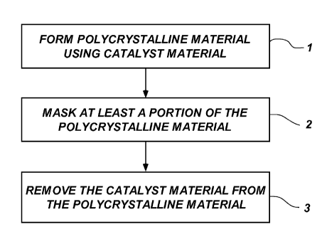
FIG. 1 is a flowchart of an embodiment of a method of forming a
polycrystalline compact cutting element according to the present disclosure;
FIGS. 2A through 2C are illustrations depicting a method of forming a
polycrystalline compact cutting element according to the embodiment of FIG. 1
;
FIG. 3A is a simplified figure illustrating how a microstructure of a region
or
layer of polycrystalline material of the cutting element shown in FIGS. 2 A
and 2B
may appear under magnification;
FIG. 3B is a simplified figure illustrating how a microstructure of a region
or
layer of polycrystalline material of the cutting element shown in FIG. 2C may
appear
under magnification; and
FIG. 4 is a perspective view of an embodiment of an earth-boring tool of the
present disclosure that includes a plurality of cutting elements formed in
accordance
with embodiments of the present disclosure.
CA 02797618 2014-05-27
- 5c -
MODE(S) FOR CARRYING OUT THE INVENTION
The illustrations presented herein are not meant to be actual views of any
particular material, apparatus, system, or method, but are merely idealized
representations which are employed to describe the present disclosure.
Additionally,
elements common between figures may retain the same numerical designation.
CA 02797618 2012-10-25
WO 2011/139760
PCT/US2011/034125
- 6 -
In some embodiments, methods of the present disclosure may be used to
fabricate polycrystalline diamond compact (PDC) cutting elements for use in
earth-boring tools, such as drill bits. The methods employ the use of a non-
acidic,
reactive material to remove catalyst material from the polycrystalline
material of the
PDC that forms the cutting element. The polycrystalline material may be formed
using
a high temperature/high pressure (HTHP) process. In some embodiments, the
polycrystalline material may be formed on a cutting element substrate, or the
polycrystalline material may be folined separately from any cutting element
substrate
and later attached to a cutting element substrate. The reactive material may
include, for
example, a molten glass, an ionic compound, a leaching liquor or a chemical
plasma.
Removing the catalyst material from the polycrystalline material using the non-
acidic,
reactive materials disclosed herein may provide improved control of a depth at
which
the catalyst material is removed.
As used herein, the term "catalyst material" refers to any material that is
capable of substantially catalyzing the formation of inter-granular bonds
between
grains of hard material during an HTHP but at least contributes to the
degradation of
the inter-granular bonds and granular material under elevated temperatures,
pressures, and other conditions that may be encountered in a drilling
operation for
foiming a wellbore in a subterranean formation. For example, catalyst
materials for
diamond include, by way of example only, cobalt, iron, nickel, other elements
from
Group VIIIA of the Periodic Table of the Elements, and alloys thereof.
As used herein, the term "drill bit" means and includes any type of bit or
tool
used for drilling during the formation or enlargement of a wellbore and
includes, for
example, rotary drill bits, percussion bits, core bits, eccentric bits, bi-
center bits,
reamers, mills, drag bits, roller cone bits, hybrid bits and other drilling
bits and tools
known in the art.
As used herein, the term "molten" means and includes a state in which a
material is viscous and in a softened or melted state through which the
material
passes in transitioning from a solid state to a liquid state.
As used herein, the term "hard material" means and includes any material
having a Knoop hardness value of about 3,000 Kgf/mm2 (29,420 MPa) or more.
Hard materials include, for example, diamond and cubic boron nitride.
CA 02797618 2012-10-25
WO 2011/139760 PCT/US2011/034125
- 7 -
As used herein, the term "inter-granular bond" means and includes any direct
atomic bond (e.g., covalent, metallic, etc.) between atoms in adjacent grains
of
material.
As used herein, the tei ___ iii "polycrystalline compact" means and includes
any
structure comprising a polycrystalline material formed by a process that
involves
application of pressure (e.g., compaction) to the precursor material or
materials used
to form the polycrystalline material.
As used herein, the term "polycrystalline material" means and includes any
material comprising a plurality of grains or crystals of the material that are
bonded
directly together by inter-granular bonds. The crystal structures of the
individual
grains of the material may be randomly oriented in space within the
polycrystalline
material.
As used herein, the term "leaching" means and includes removing or
extracting materials from a solid material (such as a polycrystalline
material) into a
carrier, such as by dissolving the materials into the carrier or by converting
the
materials into a salt.
As used herein with regard to a depth or level, or magnitude of a depth of
level, that catalyst is removed beneath a surface of a polycrystalline
compact, the
term "standard deviation" means and includes a measure of dispersion or
variation
obtained by extracting the square root of the mean of squared deviations of
observed
values from their mean in a frequency distribution. A low standard deviation
indicates that data points tend to be very close to the mean, whereas high
standard
deviation indicates that the data points are spread out over a large range of
values. A
reduced standard deviation may indicate that the observed depths of catalyst
removal
are closer to the mean and, thus, may be referred to herein as an improvement
in the
standard deviation (i.e., "improved standard deviation"). To determine an
improvement in the standard deviation, a depth at which the catalyst is
removed
beneath a surface of the polycrystalline compact may be determined using
conventional methods, such as, electron microscopy. Using the methods
described
herein, the standard deviation may be improved, for example, by up to about
80%
and, more particularly, by between about 5% and about 20%.
CA 02797618 2012-10-25
WO 2011/139760 PCT/US2011/034125
- 8 -
As used herein with regard to a depth or level, or magnitude of a depth of
level, beneath a surface of a polycrystalline compact, the terms
"substantially
unifoini" and "substantially uniformly" mean and include a depth of an area
under
the surface which is substantially devoid of significant aberrations such as
spikes
and/or valleys in excess of a general magnitude of such depth. More
specifically, a
"substantially uniform depth" when referring to a depth of catalyst removal
beneath
a surface of a polycrystalline compact means and includes a depth of such
removal
substantially free of significant aberrations such as spikes, valleys and
other
variations in the region below the surface. In other words, if catalyst is
removed to a
substantially unifoini depth below, for example, a cutting face of a
polycrystalline
compact, the catalyst is removed from an area below the surface of the cutting
face
to a depth, the boundary of which with a remainder of the compact including
such
catalyst while not necessarily constant, is free of significant aberrations
such as
spikes, valleys and/or other variations.
FIG. 1 is a process flow of an embodiment of a method of the present
disclosure. The associated structures formed during the process shown in FIG.
1 are
illustrated in FIGS. 2A through 2C. Referring to the foregoing drawing
figures, in a
first act 1, a cutting element 10 (FIG. 2A) that includes a polycrystalline
material 14 is
formed from particles of a hard material, such as diamond particles (also
known as
"grit") in the presence of a catalyst material 11 using an HTHP process. In
some
embodiments, the polycrystalline material 14 may be formed on a supporting
substrate 12, or may be attached to the supporting substrate 12 after
formation of the
polycrystalline material 14. The substrate 12 may comprise a cermet material
such as
cobalt-cemented tungsten carbide. In a second act 2, a mask, such as fixture
20
(FIG. 2B), may be formed over the substrate 12 and, optionally, a portion of
the
polycrystalline material 14 of the cutting element 10. In a third act 3, at
least a portion
of the catalyst material 11 may be removed from exposed regions of the
polycrystalline
material 14 using a non-acidic, reactive material, such as a molten glass
material, an
ionic compound, a leaching liquor or a chemical plasma, as will be described
herein
(FIG. 2C). Controlled removal of the catalyst material 11 using the reactive
material
may improve (i.e., reduce) a standard deviation of a depth at which the
catalyst
material 14 is removed from beneath a surface of PCD cutting elements, such as
CA 02797618 2012-10-25
WO 2011/139760 PCT/US2011/034125
- 9 -
cutting element 10. As used herein, the term "remove" as applied to catalyst
material 11 within the polycrystalline material 14 means and includes
substantial
removal of catalyst 11 from interstitial spaces within the polycrystalline
material 14
and from surfaces of the bonded particles of which the polycrystalline
material 14 is
comprised, and does not preclude the existence of some small quantity of
catalyst
material 11 within the region or regions of the polycrystalline material 14
from which
the catalyst material 11 has been removed. Stated another way, the
polycrystalline
material 14 may have a region or regions, or even the entirety of the
polycrystalline
material 14, which are rendered substantially free of catalyst material 11 by
a removal
process according to an embodiment of the disclosure. For example, the
standard
deviation of the depth at which the catalyst material 11 is removed may be
improved
by between about 5% and about 80%, more particularly, between about 10% and
about
20% and, more particularly still, about 15%. By way of example and not
limitation,
the reactive material may enable the catalyst material 11 to be substantially
unifoiinly
removed from the polycrystalline material 14.
FIGS. 2A through 2C illustrate an embodiment of a method of the present
disclosure. FIG. 2A is a perspective view of a cutting element 10 that may be
used, for
example, in an earth-boring tool. The cutting element 10 may include a
polycrystalline
material 14, also referred to in the art as a "polycrystalline diamond table"
or a
"diamond table." The polycrystalline material 14 of the cutting element 10 may
include a plurality of interstitial regions throughout which a catalyst
material 11 is
dispersed. The cutting element 10, 10' shown in FIGS. 2A though 2C is formed
on a
supporting substrate 12 (as shown) of cemented tungsten carbide or other
suitable
material as known in the art in a conventional process of the type described,
by way of
non-limiting example, in U.S. Patent No. 3,745,623 to Wentorf et al. (issued
July 17,
1973), or may be formed as a freestanding polycrystalline diamond compact
(i.e.,
without the supporting substrate 12) in a similar conventional process as
described, by
way of non-limiting example, in U.S. Patent No. 5,127,923 to Bunting et al.
(issued
July 7, 1992). The polycrystalline material 14 may be bonded to the supporting
substrate 12 at an interface 16. A cutting surface 18 of the polycrystalline
material 14
may be exposed opposite interface 16 as a working surface. While the cutting
element 10 in the embodiment depicted in FIG. 2A is cylindrical or disc-
shaped, in
CA 02797618 2012-10-25
WO 2011/139760 PCT/US2011/034125
- 10 -
other embodiments, the cutting element 10 may have any desirable shape, such
as a
dome, cone, chisel, etc. The polycrystalline material 14 may comprise natural
diamond, synthetic diamond, or a mixture thereof, and may be formed using
diamond
grit of different crystal sizes (i.e., from multiple layers of diamond grit,
each layer
having a different average crystal size or by using a diamond grit having a
multi-modal
crystal size distribution).
As shown in FIG. 2B, the cutting element 10 may be masked to protect or
shield the substrate 12 and, optionally, a portion of the polycrystalline
material 14
during removal of the catalyst material 11. The cutting element 10 may be
masked
using a material impervious to the reactive material. For example, the cutting
element 10 may be disposed in a fixture 20 to mask the substrate 12 and a
portion of
the polycrystalline material 14, if desired. In some embodiments, the fixture
20 may be
foimed from a heat resistant material, such as a ceramic material, a metal
material or a
metal alloy, or may be formed from a chemical resistant material, such as a
polymer
material or graphite. As a non-limiting example, the cutting element 10 may be
fitted
in a recess 22 in the fixture 20 by a shrink-fitting process. The cutting
element 10 may
be disposed in the recess 22 of the fixture 20 such that the cutting surface
18 of the
polycrystalline material 14 is exposed. Heat may then be applied to the
cutting
element 10 within the fixture 20 to cause expansion of the cutting element 10.
As the
cutting element 10 and fixture 20 cool to room temperature, a diameter of the
recess 22
in the fixture 20 may be slightly smaller than a diameter of the cutting
element 10. The
fixture 20 may be used to shield portions of the cutting element 10 when
exposure to
the reactive material is not desired, including the supporting substrate 12
and,
optionally, a portion of the polycrystalline material 14. While both the
substrate 12 and
the polycrystalline material 14 of the cutting element 10 are disposed in the
fixture 20
in the embodiment depicted in FIG. 2B, in other embodiments, the
polycrystalline
material 14 of the cutting element 10, or a portion thereof, may protrude
above the
fixture 20, as shown in broken lines, such that sidewalls of the
polycrystalline
material 14 are exposed for removal of the catalyst material therefrom
concurrently
with removal of the catalyst material 11 from the cutting surface 18. The
resulting area
of polycrystalline material 14 in such an instance may be said to form a "cap-
like"
CA 02797618 2012-10-25
WO 2011/139760 PCT/US2011/034125
- 11 -
structure of polycrystalline material 14 from which catalyst material 11 has
been
removed.
FIC. 2C illustrates the cutting element 10 after removal of the catalyst
material 11 (FIG. 2A) from at least a portion of the polycrystalline material
14. In
some embodiments, at least a portion of or substantially all of the catalyst
material 11
may be removed from the polycrystalline material 14. In other embodiments, the
catalyst material 11 is removed from portions of the polycrystalline material
14
surrounding the cutting surface 18, as shown in FIG. 2C, and the
polycrystalline
material 14 may include two general regions separated at an interface 24. A
catalyst-filled portion 26 fauns the lower portion of the polycrystalline
material 14 and
may be bonded to the supporting substrate 12. A leached portion 28 forms the
upper
portion of the polycrystalline material 14 and is adjoined to catalyst-filled
portion 26 at
interface 24. The leached portion 28 of the polycrystalline material 14
provides a
thermally stable cutting surface 18. In some embodiments, the leached portion
28
includes a polycrystalline material 14 having interstitial regions, at least a
portion of
which are substantially free of catalyst material 11. The presently disclosed
methods
enable an improvement in the standard deviation (i.e., a reduction in an
amount of
variation) of removal of the catalyst material 11 from the polycrystalline
material 14, to
a desired depth or depths. In other words, in cutting elements subjected to
conventional acid leaching processes, the methods of the present disclosure
may
provide an improvement in the standard deviation of removal of the catalyst
material 11 from within the polycrystalline material 14 of PDC cutting
elements. For
example, the standard deviation of the depth of the leached portion 28 between
cutting
elements formed using the methods of the present disclosure may be improved by
about 10% in comparison to a standard deviation in depth of leached portions
formed
using conventional acid leaching processes. In addition, the catalyst material
11 may
be substantially uniformly removed from the cutting surface 18 of the
polycrystalline
material 14 and, optionally, from the sidewalls of the polycrystalline
material 14. In
some embodiments, the catalyst material 11 may be removed from a region having
a
substantially uniform depth from the cutting surface 18 or the sidewalls of
the
polycrystalline material 14. Accordingly, removal of the catalyst material 11
using the
reactive material as described herein may reduce or eliminate the number and
depth of
CA 02797618 2012-10-25
WO 2011/139760 PCT/US2011/034125
- 12 -
spikes or variations of the leached portion 28 that extend past a desired
depth of the
interface 24 between the catalyst-filled portion 26 and the leached portion
28. For
example, if the polycrystalline material 14 has a depth of between about 1 mm
and
about 3 mm, in one embodiment the catalyst material 11 may be removed or
leached
from the polycrystalline material 14 to a depth of less than about one hundred
micrometers (100 rn or 0.1 mm) and, more particularly, between about twenty
five
micrometers (25 jam or 0.025 mm) and about ninety-five micrometers (95 m or
0.095
mm). In another embodiment, the catalyst material may be removed to a depth of
more
than about one hundred micrometers (100 m, or 0.1 mm), for example, to as
much as
five hundred micrometers (500 m or 0.5 mm) or, in one case, to a depth
selected from
within a range of between about two hundred fifty micrometers (250 m or 0.25
mm)
and about three hundred micrometers (300 m or 0.3 mm).
The catalyst material 11 may be removed from the interstices of the
polycrystalline material 14 to form the thermally stable cutting surface 18 by
exposing
the polycrystalline material 14 to a reactive material. The reactive material
may
include, for example, a molten glass, a molten salt, a leaching liquor, a
eutectic liquid
or a chemical plasma. In some embodiments, the polycrystalline material 14 or
the
cutting surface 18 thereof may be exposed to the reactive material while the
cutting
element 10 is disposed within the fixture 20 to preclude contact between the
reactive
material and a shielded region of the polycrystalline material 14 and the
supporting
substrate 12, if present.
In some embodiments, the reactive material may include a glass material in a
molten state. The glass material may be a silicate glass, such as a
borosilicate glass, an
aluminosilicate glass, a high silica glass, phosphosilicate glass (PSG) or
borophosphosilicate glass (BPSG). In some embodiments, a sodium material (also
referred to as a "flux material") may be added to the glass material to
substantially
reduce a melting point of the glass material. The sodium material may include,
for
example, sodium hydroxide, sodium carbonate, sodium borohydrate or sodium
chloride. By way of non-limiting example, the glass material may have a
melting point
of less than or equal to about one thousand degrees Celsius (1,000 C) and,
more
particularly, between about twenty degrees Celsius (20 C) and about nine
hundred
degrees Celsius (900 C) and, more particularly still, between about three
hundred
CA 02797618 2012-10-25
WO 2011/139760
PCT/US2011/034125
- 13 -
= degrees Celsius (300 C) and about seven hundred fifty degrees Celsius
(750 C). In
some embodiments, the glass material may be introduced to the cutting element
10 at a
temperature of greater than or equal to about a melting point of the glass
material. By
way of non-limiting example, the glass material may be introduced to the
polycrystalline material 14 of the cutting element 10 in a chamber (not shown)
of a
conventional furnace or reactor. A temperature within the chamber may be
controlled
to maintain the glass material in a molten state during the removal of the
catalyst
material 11 from the polycrystalline material 14. In other embodiments, the
glass
material may be heated to a molten state and the polycrystalline material 14
of the
cutting element 10 may be immersed in the molten glass material or may be
inverted
and dipped into the molten glass material. In the molten state, the glass
material may
corrode, dissolve or otherwise remove the catalyst material 11 from a portion
of the
polycrystalline material 14 such that at least a portion of the interstices of
the portion of
the polycrystalline material 14 are substantially free of catalyst material
11.
In other embodiments, the reactive material may include an ionic compound
such as, a salt, a mixture of salts or a mixture of compounds that may produce
a salt.
The ionic compounds may be selected to selectively dissolve the catalyst
material 11
with respect to the polycrystalline material 14. The ionic compound may be a
salt of,
for example, an alkali metal (i.e., elements from Group I of the Periodic
Table of the
Elements), such as lithium, sodium, potassium, rubidium, cesium, and francium
or may
be a salt of calcium, silica or aluminum. The ionic compound may also be a
nitrate, a
fluoroborate, an ethanoate, a hexafluorophosphate or a halide. The ionic
compound
may have a melting temperature of less than or equal to four hundred degrees
Celsius
(400 C) and, more particularly, between about twenty degrees Celsius (20 C)
and
about three hundred degrees Celsius (300 C). The cutting element 10 may be
exposed
to the ionic compound at a pressure of less than or equal to five kilobar (5
kbar) and,
more particularly, between about one-half of a kilobar (0.5 kbar) and about
three
kilobar (3 kbar). To remove the catalyst material 11 from the polycrystalline
material 14, the ionic compound may be introduced to the polycrystalline
material 14 at
a temperature of greater than or equal to a melting point of the ionic
compound. For
example, the ionic compound may be heated to a molten state and the cutting
element 10 may be immersed or dipped into the molten ionic compound. The
molten
CA 02797618 2012-10-25
WO 2011/139760 PCT/US2011/034125
- 14 -
ionic compound may corrode, dissolve or otherwise remove the catalyst material
11
from a portion of the polycrystalline material 14 such that the interstices of
the portion
of the polycrystalline material 14 are substantially free of catalyst material
11.
In additional embodiments, the reactive material may include a leaching liquor
that may dissolve the catalyst material 11 enabling removal of the catalyst
material 11
from the cutting element 10. As used herein, the term "leaching liquor" means
and
includes liquid that may remove the catalyst material 11 from the
polycrystalline
material 14 by, for example, dissolving the catalyst material 11 or converting
the
catalyst material into a soluble salt. Suitable leaching liquors are known in
the art and
are described, by way of non-limiting example, in U.S. Patent No. 3,673,154 to
Treyvillyan et al. (issued June 27, 1972), U.S. Patent No. 4,490,298 to Feld
et al.
(issued December 25, 1984). For example, the catalyst material 11 may be
exposed to
a leaching liquor formed by liquid phase oxidation of meta- or para-xylenes to
isophthalic acid or terephthalic acid, with an oxidation catalyst (e.g.,
cobalt acetate) in
the presence of an acetic acid solvent medium, which may dissolve the catalyst
material 11 and Rhin a phthalic acid. The phthalic acid, the acetic acid and
water may
be removed from the reaction mixture and the resulting mixture may be treated
with
aqueous sodium carbonate such that a carbonate of the catalyst material 11 is
formed.
As another non-limiting example, the catalyst material 11 may be exposed to a
solution
of acetic acid and water and, thereafter, an oxalic acid or oxalic acid ester
may be
added to the solution to faun an oxalate of the catalyst material 11.
In further embodiments, the reactive material may be introduced to the
polycrystalline material 14 of the cutting element 10 in the form of a liquid
foiming
eutectic reaction. In some embodiments, a binary eutectic may be formed by one
or
more rare earth elements, such as, germanium, yttrium, neodymium, cerium, and
gadolinium. As a non-limiting example, the one or more elements may be
liquefied by
heating the one or more elements to a temperature of greater than or equal to
a melting
point thereof. For example, a germanium metal may be liquefied by heating to a
temperature of about nine hundred thirty-eight degrees Celsius (938 C). The
liquefied
element, such as liquid gemianium, may be combined with about 15 wt% cobalt
and
cooled to a temperature of about seven hundred thirty degrees Celsius (730 C)
to form
a eutectic liquid, which remains a liquid as described in the phase diagram
relation
CA 02797618 2012-10-25
WO 2011/139760 PCT/US2011/034125
- 15 -
between cobalt and germanium. The phase diagram relation between cobalt and
germanium is described in detail in, for example, K. Ishida and T. Nishizawa,
Journal
of Phase Equilibria, vol. 12, No. 1, pp. 77-83 (1991). The cutting element 10
may be
exposed to the eutectic liquid at a pressure of less than or equal to about
five kilobar (5
kbar) and, more particularly, between about one-half of a kilobar (0.5 kbar)
and about
three kilobar (3 kbar). To remove the catalyst material 11 from the
polycrystalline
material 14, the eutectic liquid may be introduced to the polycrystalline
material 14 at a
temperature of greater than or equal to a melting point of an eutectic liquid
phase. For
example, after forming the eutectic liquid, the cutting element 10 may be
immersed or
dipped into the eutectic liquid, which may be maintained in a molten state.
The molten
eutectic liquid may corrode, dissolve or otherwise remove the catalyst
material 11 from
a portion of the polycrystalline material 14 such that the interstices of the
portion of the
polycrystalline material 14 are substantially free of catalyst material 11.
In yet further embodiments, the reactive material may be introduced to the
polycrystalline material 14 of the cutting element 10 in the form of a
chemical plasma.
In some embodiments, the chemical plasma may include one or more inert gases,
such
as, argon, nitrogen, helium, xenon, krypton and radon. In other embodiments,
the
chemical plasma may include an oxidizing agent, such as oxygen (02), ozone
(03),
fluorine (F2), chlorine (C12), peroxides, and the like. The chemical plasma
may be
generated as known in the art in a conventional process of the type described,
by way
of non-limiting example, in U.S. Patent No. 4,494,620 to Matsuo et al. (issued
January 8, 1985), U.S. Patent No. 4,361,472 to Morrison (issued November 30,
1982),
and H. Conrads and M. Schmidt, "Plasma Generation and Plasma Sources," Plasma
Sources Sci. Technol. 9:441-454 (2000). The cutting element 10 may be placed
in a
chamber of a conventional plasma reactor and the chamber may be at least
partially
evacuated. One or more of the inert gases and the oxidizing agents may then be
introduced into the plasma reactor and the chamber. The chemical plasma may be
generated in a microwave electric field or in a high-frequency electric field
under a
reduced pressure. The polycrystalline material 14 may be used as a sputtering
target
and ions in the chemical plasma may bombard the catalyst material 11 resulting
in
ejection of the catalyst material 11 from the interstitial regions of the
polycrystalline
material 14. As a non-limiting example, an electric field may be used to
direct the
CA 02797618 2012-10-25
WO 2011/139760 PCT/US2011/034125
- 16 -
ejected catalyst material 11 away from the cutting surface 18 of the
polycrystalline
material 14 and toward a dummy plating material. By way of non-limiting
example,
the chemical plasma may be contacted with the polycrystalline material 14 at a
temperature of between about three hundred degrees Celsius (300 C) and about
seven
hundred fifty degrees Celsius (750 C).
While the cutting element 10 may be exposed to the reactive material at a
temperature of less than about four hundred degrees Celsius (400 C) to prevent
internal
stress, the temperature of the reactive material may be increased to less than
or equal to
about seven hundred fifty degrees Celsius (750 C) to increase a rate of
removal of the
catalyst material 11 from the polycrystalline material 14. The cutting
elements 10, 10'
formed according to embodiments of methods of the present disclosure may
provide
reduce the variation (i.e., the standard deviation) in depth of removal of the
catalyst
material 11 from the polycrystalline material 14 of PDC cutting elements in
comparison to the variation in the depth of removal of the catalyst material
from PCD
cutting elements using conventional acid leaching process. For example, the
standard
deviation of the depth of removal of the catalyst material 11 throughout the
polycrystalline material 14 of PDC cutting elements (i.e., cutting element 10)
may be
reduced by between about 15% and about 20%. In addition, removal of the
catalyst
material 11 using the methods of the present disclosure may enable formation
of the
leached portion 28 extending to a desired depth within the polycrystalline
material 14
without significant spikes or variations extending therepast. Forming the
cutting
element 10 according to embodiments of the present disclosure enables removal
of the
catalyst material 11 from the polycrystalline material 14 at reduced
temperatures to
prevent reverse graphitization of the polycrystalline material 14.
Furthermore, forming
the cutting element 10 according to embodiments of the present disclosure
substantially
reduces or eliminates hazardous acid wastes that are produced during
conventional acid
leaching processes.
FIG. 3A is an enlarged view illustrating how a microstructure of the
polycrystalline material 14 shown in FIGS. 2A and 2B may appear under
magnification. As shown in FIG. 3A, the polycrystalline material 14 includes
diamond
crystals 30 that are bonded together by inter-granular diamond-to-diamond
bonds. The
catalyst material 11 used to catalyze the formation of the inter-granular
CA 02797618 2012-10-25
WO 2011/139760 PCT/US2011/034125
- 17 -
diamond-to-diamond bonds is disposed in interstitial regions or spaces between
the
diamond crystals 30.
FIG. 3B is an enlarged view illustrating how a microstructure of the
polycrystalline material 14 shown in FIG. 2C may appear under magnification.
As
shown in FIG. 3B, after removal of at least a portion of the catalyst material
11 using
embodiments of the methods described herein, cavities or voids 32 may be
present in
interstitial regions or spaces between the diamond crystals 30. The methods
disclosed
herein enable removal of the catalyst material 11 from the polycrystalline
material 14 at
temperatures of less than or equal to seven hundred fifty degrees Celsius (750
C),
which prevents internal stress within the cutting element (e.g., reverse
graphitization)
caused by increased temperatures.
FIG. 4 is a perspective view of an embodiment of an earth-boring rotary drill
bit 100 of the present disclosure that includes a plurality of cutting
elements 10 having
a structure as shown in FIG. 2C, or other polycrystalline material structure
having
catalyst removed from one or more portions thereof according to the
disclosure. The
earth-boring rotary drill bit 100 includes a bit body 102 that is secured to a
shank 104
having a threaded connection portion 106 (e.g., an American Petroleum
Institute (API)
threaded connection portion) for attaching the drill bit 100 to a drill string
(not shown).
In some embodiments, such as that shown in FIG. 4, the bit body 102 may
comprise a
particle-matrix composite material, and may be secured to the metal shank 104
using
an extension 108. In other embodiments, the bit body 102 may be secured to the
shank 104 using a metal blank embedded within the particle-matrix composite
bit
body 102, or the bit body 102 may be secured directly to the shank 104.
The bit body 102 may include internal fluid passageways (not shown) that
extend between the face 103 of the bit body 102 and a longitudinal bore (not
shown),
which extends through the shank 104, the extension 108, and partially through
the bit
body 102. Nozzle inserts 124 also may be provided at the face 103 of the bit
body 102
within the internal fluid passageways. The bit body 102 may further include a
plurality
of blades 116 that are separated by junk slots 118. In some embodiments, the
bit
body 102 may include gage wear plugs 122 and wear knots 128. A plurality of
cutting
elements 10', as previously disclosed herein, may be mounted on the face 103
of the bit
body 102 in cutting element pockets 112 that are located along each of the
blades 116.
CA 02797618 2012-10-25
WO 2011/139760 PCT/US2011/034125
- 18 -
The cutting elements 10 are positioned to cut a subterranean formation being
drilled
while the drill bit 100 is rotated under weight-on-bit (WOB) in a borehole
about
centerline L100.
Embodiments of cutting elements of the present disclosure also may be used as
gauge trimmers, and may be used on other types of earth-boring tools. For
example,
embodiments of cutting elements of the present disclosure also may be used on
cones
of roller cone drill bits, on reamers, mills, bi-center bits, eccentric bits,
coring bits, and
so-called "hybrid bits" that include both fixed cutters and rolling cutters.
While the present disclosure has been described herein with respect to certain
embodiments, those of ordinary skill in the art will recognize and appreciate
that it is
not so limited. Rather, many additions, deletions and modifications to the
described
embodiments may be made without departing from the scope of the disclosure as
hereinafter claimed, including legal equivalents. In addition, features from
one
embodiment may be combined with features of another embodiment while still
being encompassed within the scope of the disclosure as contemplated by the
inventors.