Note: Descriptions are shown in the official language in which they were submitted.
CA 02797790 2012-10-26
WO 2011/143116 PCT/US2011/035760
1
Bone Screw Assembly and Instruments for Implantation of the Same
Inventors: Tom OVERES, Silas ZURSCHMIEDE and Daniel FLURI
Priority Claim
[0001] The present invention claims priority to U.S. Provisional Application
Serial No.
61/334,234 filed on May 13, 2010 and entitled, "Bone Screw Assembly and
Implantation
of the Same," the entire disclosure of which is incorporated herein by
reference.
Field of the Invention
[0002] The present invention generally relates to bone screw assemblies and
instruments for implantation of the same as well as to an associated method
for
implantation of the bone screw assembly using the instruments. More
particularly, the
invention relates to a bone screw including a second screw and insertion
instruments for
implantation of the same as well as to a method for implantation of the bone
screw and
the second screw by using the insertion instruments.
Background
[0003] In the field of orthopedic surgery bone fixation devices using bone
screws are
commonly used. These bone fixation devices include bone plates, intervertebral
implants or intramedullary nails by means of which two or more bones or bone
fragments are fixed relative to each other. Typically, the bone fixation
devices comprise
bone anchors mostly in the form of bone screws, pins or nails by means of
which the
bones or bone fragments are fixed to the bone plate, intervertebral implant or
intramedullary nail and consequently fixed relative to each other. One problem
that can
arise in case of the above mentioned bone fixation devices is that the bone
screws, pins
or nails can for instance become dislodged in the bone or in the bone plate,
intervertebral implant or intramedullary nail during normal movements of the
patient.
CA 02797790 2012-10-26
WO 2011/143116 PCT/US2011/035760
2
[0004] Thus, there remains a need for an improved bone anchor device for use
in bone
fixation that allows to drill a hole for a securing screw into a bone under a
particular
angle with respect to the axis of a bone fastener and to insert the securing
screw in a
guided manner.
Summary of the Invention
[0005] The present invention relates to a bone screw with a screw head
configured to
be releasably coupled to a surgical instrument or tool such that the surgical
instrument
or tool is coaxially supported in a first position and can be pivoted in a
guided manner
about an axis extending diametrically to the screw head into a second
position.
[0006] According to an exemplary embodiment of the present invention, the bone
screw
comprises a screw axis, a shaft to be anchored in a bone and screw head
including a
through hole with a through hole axis cutting the axis of the bone screw at an
acute
angle wherein the through hole is adapted to receive a second screw that can
be
anchored in the bone as well. The screw head comprises a transverse channel
with a
channel axis extending diametrically across the screw head and wherein the
transverse
channel is open at the rear end of the bone screw. The screw head of the bone
screw
further includes a recess which has - in at least a cross-section orthogonal
to the
channel axis - a circularly curved edge with a centre located at the point
where the
through hole axis cuts the screw axis.
[0007] One of the advantages of the bone screw according to the invention is
that the
configuration of the transverse channel and the recess permits an aiming guide
with a
complementarily configured tip to be attached to the screw head and rotated
about a
rotation axis from a first position aligned with the screw axis into a second
position
aligned with the through hole axis. Another advantage of the bone screw is the
pivotable joining of the screw head and the aiming guide. The aiming guide can
be
inserted into the incision coaxially to the screw axis of the bone screw by
using a tissue
CA 02797790 2012-10-26
WO 2011/143116 PCT/US2011/035760
3
protection tube and/or a guide wire and attached to the screw head. After
removing the
tissue protection tube and/or the guide wire the aiming guide can be rotated
about the
rotation axis. In addition, the aiming guide can then be rotated into a second
position in
which the longitudinal axis of the aiming guide is aligned with the through
hole axis of
the through hole in the screw head so that a bore hole for the second screw
can be
drilled into the bone which is exactly aligned with the through hole in the
screw head;
the bore hole for the second screw can be drilled in a completely guided
manner and
the second screw can be positioned in a guided manner by means of the aiming
guide.
Another advantage is that the transverse channel and the recess allow to
attach a
complementarily formed tip of a screwdriver to the bone screw in such a manner
that
the screwdriver is positioned coaxially to the screw axis of the bone screw.
[0008] In an exemplary embodiment of the bone screw, the through hole axis
cuts the
screw axis at a depth T > 0 measured from the rear end of the bone screw
towards the
screw shaft.
[0009] In another exemplary embodiment of the bone screw, the recess has a
constriction at the rear end of the bone screw. Thus, the recess forms a
female
connector for a snap-lock connection with a respective male connector arranged
at a
surgical instrument or tool.
[0010] In a further exemplary embodiment of the bone screw, the through hole
comprises an internal thread, preferably a conical internal thread. This
allows the
advantage that the second screw can be firmly connected to the screw head of
the bone
screw.
[0011] In another exemplary embodiment of the bone screw, the internal thread
has a
thread pitch P and a threaded length LT and wherein the ratio LT / P is
minimum 2.0,
preferably minimum 2.3. This configuration of the internal thread allows a
rigid and
angularly stable anchorage of the screw head of the second screw in the screw
head of
the bone screw.
CA 02797790 2012-10-26
WO 2011/143116 PCT/US2011/035760
4
[0012] In yet another exemplary embodiment of the bone screw, the recess has a
spherical shape with a radius of the sphere R. This configuration of the
recess allows a
surgical instrument or tool to be pivoted about an axis which extends through
the point
where the through hole axis and the screw axis intersect so that the
instrument or tool
can be pivoted from a first position aligned with the screw axis to a second
position
aligned with the through hole axis.
[0013] In a further exemplary embodiment, the bone screw further comprises a
second
screw insertable into the through hole coaxially to the through hole axis.
[0014] In another exemplary embodiment of the bone screw, the second screw has
a
conically threaded head engagable with the conical internal thread in the
through hole.
[0015] In yet a further exemplary embodiment of the bone screw, the recess
includes a
depression traversing the constriction and forming a wall portion with the
shape of a
surface section of a cylinder, cone or prism the axis of which coincides with
the through
hole axis. By means of the depression a stop for the rotation of an instrument
or tool
inserted in the recess in the screw head of the bone screw is provided so that
the
instrument or tool can be exactly aligned with the through hole for the second
screw.
[0016] In another exemplary embodiment of the bone screw, the angle a amounts
to
minimum 10 , preferably to minimum 20 .
[0017] In yet another exemplary embodiment of the bone screw, the angle a
amounts
to maximum 70 , preferably to maximum 35 .
[0018] In again another exemplary embodiment of the bone screw, the transverse
channel has a U-shape in a cross-section orthogonal to the channel axis. The U-
shaped
channel can have a semicircular bottom with a radius of curvature rc, wherein
the centre
of the semicircular edge of the transverse channel is located on the channel
axis. The
CA 02797790 2012-10-26
WO 2011/143116 PCT/US2011/035760
channel axis can be located at a depth Tc measured from the rear end of the
bone
screw towards the screw shaft, wherein the depth Tc is equal or greater than
the depth
T of the point where the through hole axis cuts the screw axis. In a
particular
configuration of the transverse channel the channel axis cuts the screw axis
through the
point where the through hole axis and the screw axis intersect, i.e. Tc = T.
In this case
the semicircular bottom defines a seat coaxially to the recess for rotatably
receiving
cylindrical pins of an aiming guide which have a pin diameter equal to twice
the radius
of curvature rc of the semicircular bottom of the transverse channel. In case
of a
spherical recess the rotatable movement of the aiming guide is limited to a
uniaxial pivot
movement due to the pins engaging the transverse channel.
[0019] In a further exemplary embodiment of the bone screw, the channel axis
cuts the
screw axis through the point at which the screw axis and the through hole axis
intersect.
[0020] In yet another exemplary embodiment of the bone screw, the screw head
of the
bone screw comprises an external thread designed in such a manner that the
bone
screw can be counter-sunk in a bone. The external thread on the screw head is
preferably_conical so that it allows to countersink the screw head in the
bone. This
configuration is particularly useful if the bone screw is used as a locking
screw for an
intramedullary nail.
[0021] In another exemplary embodiment of the bone screw, the screw head of
the
bone screw has a longitudinal slot so that the screw head is radially
elastically
expandable. The screw head can have the shape of a segment of a sphere so that
the
bone screw can be inserted into a complementarily shaped hole in a bone plate
or other
implant under a surgeon desired angle. Once the bone screw is correctly
positioned the
second screw can be inserted until the head of the second screw expands the
screw
head of the bone screw in the hole so allowing to secure the bone screw in a
surgeon
selected angle relative to a bone plate or other implant.
CA 02797790 2012-10-26
WO 2011/143116 PCT/US2011/035760
6
[0022] In accordance with another aspect of the present invention, a
screwdriver is
provided for screwing the above bone screw into a bone. The screwdriver
essentially
comprises a male connector terminally arranged at the front end which is
suitable to be
coupled to the recess in the screw head of the bone screw. Further, the
connector
includes a tip constricting towards the front end of the screwdriver and two
driving
protrusions diametrically projecting over the tip in either direction and
defining a central
axis which extends orthogonal to the longitudinal axis of the screwdriver. The
driving
protrusions fit in the transverse channel in the screw head of the bone screw.
In at least
a cross-section orthogonal to the central axis the tip has a circularly curved
periphery
with a radius R and a centre located on the longitudinal axis. The driving
protrusions
can have the shape of pins or blades. In case of blade-shaped driving
protrusions the
tips of the blades define the central axis. In case of pin-shaped driving
protrusions the
axes of the pins define the central axis.
[0023] In an exemplary embodiment, the screwdriver further comprises a
longitudinal
slot extending parallel to the longitudinal axis and which is open at the
front end so that
the connector is radially elastically compressible. Further, the tip has a
constriction
towards the shaft which forms at least in a cross-section orthogonal to the
central axis a
curved contact shoulder. Thus, the connector forms a male connector for a snap-
lock
connection with a respective female connector arranged at the bone screw.
[0024] In a further exemplary embodiment of the screwdriver, the tip has a
spherical
shape with a radius of the sphere R and with a centre located on the
longitudinal axis.
[0025] In a further exemplary embodiment of the screwdriver, the two driving
protrusions are circular-cylindrically shaped wherein the central axis
orthogonally cuts
the longitudinal axis through the centre of the spherical tip.
[0026] In another exemplary embodiment of the screwdriver, the male connector
further
comprises an axial stop located at a distance T measured from the central axis
towards
the shaft so that the stop contacts the rear end of the bone screw when the
connector is
CA 02797790 2012-10-26
WO 2011/143116 PCT/US2011/035760
7
coupled to the recess in the screw head. Thus, the screwdriver is kept exactly
coaxially
to the screw axis of the bone screw when the stop abuts the rear end of the
bone screw.
[0027] In yet another exemplary embodiment of the screwdriver, the male
connector
further includes a nose projecting over the tip in a direction towards the
front end and at
an acute angle with respect to the longitudinal axis of the screwdriver. This
configuration
allows the advantage that the screwdriver can only be inserted in one
orientation into
the seat in the screw head of the bone screw.
[0028] In again another exemplary embodiment, the screwdriver further
comprises a
coaxial through bore penetrating through the shaft and the male connector and
having
an internal thread for engaging an external thread arranged on a locking pin
which is
insertable in the through bore in such a manner that the locking pin can be
advanced
towards the front end of the screwdriver to prevent the tip from radially
collapsing.
[0029] In accordance with a further aspect of the present invention, an aiming
guide is
provided for drilling a hole in the bone the axis of which coincides with the
through hole
axis of the through hole in the screw head of the bone screw. The aiming guide
essentially comprises a guide sleeve, a coaxial through bore and a male
connector
terminally arranged at the front end which is suitable to be coupled to the
recess in the
screw head of the bone screw. The connector includes a tip a width of which
decreases
towards the front end of the aiming guide and two pins diametrically
projecting over the
tip in either direction and coaxially arranged on a central axis which extends
orthogonal
to the longitudinal axis. In at least-a cross-section orthogonal to the
central axis the tip
has a circularly curved periphery with a radius R and a centre located on the
longitudinal axis.
[0030] In an exemplary embodiment, the aiming guide further comprises a
longitudinal
slot extending parallel to the longitudinal axis and which is open at the
front end so that
the connector is radially elastically compressible. Additionally, a curved
contact shoulder
is formed at the proximal end of the tip. Specifically, the curved contact
shoulder is
CA 02797790 2012-10-26
WO 2011/143116 PCT/US2011/035760
8
formed by a constriction at the proximal end of the tip (adjacent the guide
sleeve) where
a cross-sectional area of the tip in a plane orthogonal to the central axis of
the tip is
reduced relative to a maximum diameter portion of the tip distal thereto. This
configuration allows the connector to operate as a male connector for a snap-
lock
connection with a respective female connector arranged in the bone screw.
[0031] In another exemplary embodiment of the aiming guide, the tip has a
spherical
shape with a radius of the sphere R and with a center located on the
longitudinal axis.
[0032] In a further exemplary embodiment of the aiming guide, the two pins are
circular-
cylindrically shaped and wherein the central axis orthogonally cuts the
longitudinal axis
through the centre of the spherical tip. The circular cylindrical pivot pins
are coaxially
and rotatably insertable in the transverse channel.
[0033] In yet another exemplary embodiment of the aiming guide, a cylindrical
or
conical collar is arranged between the tip and the guide sleeve coaxially to
the
longitudinal axis of the aiming guide.
[0034] In again another exemplary embodiment of the aiming guide, the collar
has a
radius r:5 R.
[0035] In a further exemplary embodiment, the aiming guide further comprises a
drill
guide which can be inserted into the through hole.
[0036] In another exemplary embodiment of the aiming guide, the drill guide
has a
conical tip. The conical tip is shaped in such a manner that it fits into the
tapered
through hole in the bone screw. This allow to lock the drill guide aligned to
the through
hole axis of the through hole for the second screw.
[0037] In accordance with yet another aspect of the present invention, an
assembly
including a bone screw, a screwdriver and an aiming guide is provided. This
assembly
CA 02797790 2012-10-26
WO 2011/143116 PCT/US2011/035760
9
can be used if a standard locking screw which is commonly available can be
inserted
into the through hole in the bone screw.
[0038] In accordance with again another aspect of the present invention, an
assembly
including a bone screw, a tissue protection tube, an aiming guide and a
screwdriver is
provided.
[0039] In accordance with still another aspect of the present invention, a
method for
bone fixation using an intramedullary nail including a number of proximal and
distal
locking holes and a number of bone screws with a second screw each is
provided. The
method essentially comprises the steps of:
a) performing an incision into the tissue surrounding a bone to be treated;
b) positioning an intramedullary nail in the bone;
c) coupling an aiming device to the intramedullary nail;
d) inserting a tissue protection tube into a selected guide bore in the aiming
device
coaxially to one of the locking holes;
e) drilling a first bore hole into a bone for insertion a bone screw by using
the aiming
device, wherein the first bore hole is aligned with the selected proximal or
distal
locking hole;
f) coupling a bone screw to the connector of the screwdriver;
g) advancing the bone screw through the tissue protection tube;
h) screwing the bone screw into the bone using the screwdriver;
i) removing the screwdriver;
j) inserting the aiming guide through the tissue protection tube;
k) attaching the aiming guide to the bone screw in such a manner that the
longitudinal axis of the aiming guide is aligned with the screw axis of the
bone
screw;
I) removing the tissue protection tube;
m) repeating steps d) to I) until a bone screw each is inserted in all or in
the selected
proximal and/or distal locking holes of the intramedullary nail;
n) removing the aiming device from the intramedullary nail;
CA 02797790 2012-10-26
WO 2011/143116 PCT/US2011/035760
o) pivoting the aiming guide about the central axis until the collar of the
aiming
guide abuts a stop in the recess in the screw head of the bone screw so that
the
longitudinal axis of the aiming guide is aligned with the through hole axis of
the
through hole in the bone screw;
p) inserting the drill guide into the through bore in the aiming guide;
q) drilling a second bore hole into the bone using the drill guide as a guide
for the
drill bit;
r) removing the drill guide;
s) inserting the second screw through the through bore in the aiming guide;
t) advancing the second screw into the bone;
u) removing the aiming guide;
v) repeating steps o) to u) until a second screw each is anchored in the bone
passing through the through hole of each of the bone screws; and
w) closing the incision.
[0040] Instead of subsequently performing steps d) to I) for one bone screw
and
repeating the sequence for each bone screw to be inserted each step can be
repeated
for all or for the selected number of bone screws to be inserted. Similarly,
each step for
inserting the second screw can be repeated for all or for the selected number
of bone
screws instead of subsequently performing steps o) to u) for one bone screw
and
repeating the sequence for each bone screw to be inserted.
[0041] In an exemplary embodiment, the stop is formed by the wall portion of
the
depression in the recess in the screw head of the bone screw.
Brief Description of the Drawings
[0042] An exemplary embodiment of the present invention will be described in
the
following by way of example and with reference to the accompanying drawings in
which:
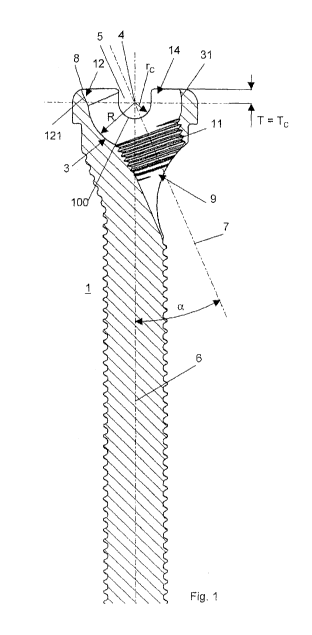
[0043] Fig. 1 illustrates a longitudinal section of an embodiment of the bone
screw
according to the invention;
CA 02797790 2012-10-26
WO 2011/143116 PCT/US2011/035760
11
[0044] Fig. 2 illustrates a lateral view of the embodiment of the bone screw
of Fig. 1;
[0045] Fig. 3 illustrates a perspective view of an embodiment of the
screwdriver
according to the invention;
[0046] Fig. 4 illustrates a longitudinal section of the embodiment of the
screwdriver of
Fig. 3;
[0047] Fig. 5 illustrates a lateral view of the embodiment of the screwdriver
of Fig. 3;
[0048] Fig. 6 illustrates a lateral view of the embodiment of the screwdriver
of Fig. 3
which is orthogonal to the lateral view of Fig. 5;
[0049] Fig. 7 illustrates a lateral view of another embodiment of the
screwdriver
according to the invention;
[0050] Fig. 8 illustrates a lateral view of the embodiment of the screwdriver
of Fig. 7
which is orthogonal to the lateral view of Fig. 7;
[0051] Fig. 9 illustrates a partial section through the embodiment of the
screwdriver of
Figs. 7 and 8 and a bone screw attached thereto;
[0052] Fig. 10 illustrates a perspective view of an embodiment of the aiming
guide
according to the invention;
[0053] Fig. 11 illustrates a longitudinal section through the embodiment of
the aiming
guide of Fig. 10 and a bone screw coaxially attached thereto;
[0054] Fig. 12 illustrates a longitudinal section through the embodiment of
the aiming
guide of Fig. 10 and a bone screw attached thereto under the angle a;
CA 02797790 2012-10-26
WO 2011/143116 PCT/US2011/035760
12
[0055] Fig. 13 illustrates a longitudinal section through the embodiment of
the aiming
guide of Fig. 10 and a bone screw attached thereto under the angle a and
together with
a drill guide inserted in the aiming guide and a drill bit;
[0056] Fig. 14 illustrates a section through the aiming device and the drill
guide of Fig.
13;
[0057] Fig. 15 illustrates a longitudinal section through the embodiment of
the aiming
guide of Fig. 10 and a bone screw attached thereto under the angle a and
together with
a second screw inserted in the aiming guide;
[0058] Fig. 16 illustrates a longitudinal section through the embodiment of
the aiming
guide of Fig. 10 and a bone screw attached thereto under the angle a and
together with
a second screw firmly secured in the through hole in the screw head of the
bone screw;
and
[0059] Fig. 17 illustrates an intramedullary nail together with a bone screw
and a
second screw according to an embodiment of the method for bone fixation
according
the invention.
[0060] Fig. 18 illustrates a lateral view of a system according to an
alternate
embodiment of the present invention, in a first configuration.
[0061] Fig. 19 illustrates a lateral view of the system of Fig. 18, in a
second
configuration.
[0062] Fig. 20 illustrates a cross-sectional lateral view of the system of
Fig. 18, in the
second configuration.
CA 02797790 2012-10-26
WO 2011/143116 PCT/US2011/035760
13
[0063] Fig. 21 illustrates an enlarged cross-sectional lateral view of a
portion of the
system of Fig. 18.
Detailed Description
[0064] The present invention may be further understood with reference to the
following
description and the appended drawings, wherein like elements are referred to
with the
same reference numerals. The present invention relates to bone screw
assemblies and
instruments for implantation of the same as well as to an associated method
for
implantation of the bone screw assembly using the instruments. In particular,
the
invention relates to a system and method facilitating implantation of a first
bone screw,
including a through hole extending through a head portion thereof along a
through hole
axis, and a second screw inserted into the through hole along the through hole
axis
such that the first and second bone screws are implanted into a bone in a
stable
configuration.
[0065] Figs. 1 and 2 illustrate an embodiment of the bone screw 1 with a screw
head 2
comprising a conical external thread 29. The bone screw 1 includes a screw
axis 6, a
threaded shaft 10, a screw head 2 and a rear end 8 at a proximal end thereof.
The
screw head 2 comprises a through hole 9 penetrating through the screw head 2
and
having a through hole axis 7 cutting the screw axis 6 under an acute angle a.
The
through hole axis 7 cuts the screw axis 2 at a depth T measured from the rear
end 8 of
the bone screw 1. The through hole 9 has a conical internal thread 11. A
second screw
50 (Figs. 16 and 17) can be inserted into the through hole 9 coaxially to the
through
hole axis 7. The second screw 50 has a conically threaded head 51 which is
engagable
with the conical internal thread 11 in the through hole 9. The screw head 2
includes a
concave seat 14 for releasably coupling a surgical instrument or tool to the
bone screw
1. The concave seat 14 comprises a transverse channel 5 and a centrally
located
recess 3. The transverse channel 5 comprises a channel axis 101 located at a
depth Tc
measured from the rear end 8 of the bone screw 1 and diametrically extending
across
the screw head 2. The channel axis 101 cuts the screw axis 6 through the point
where
CA 02797790 2012-10-26
WO 2011/143116 PCT/US2011/035760
14
the through hole axis 7 cuts the screw axis 6. Further, the transverse channel
5 is open
at the rear end 8 of the bone screw 1 and the transverse channel 5 has a U-
shaped
cross-section with a semicircular bottom 100 orthogonal to the channel axis
101. The
semicircular bottom 100 has a radius of curvature rc wherein a center of an
edge the
semicircular bottom 100 of the transverse channel 5 is located on the channel
axis 101.
The depth Tc is equal to the depth T of the point where the through hole axis
7 cuts the
screw axis 1. The semicircular bottom 100 defines a seat coaxially to the
recess 3 for
rotatably receiving cylindrical pins 25 of an aiming guide 23 (Fig. 10) which
have a pin
diameter equal to twice the radius of curvature rc of the semicircular bottom
100 of the
transverse channel 5.
[0066] The recess 3 has a spherical shape with a radius of the sphere R and a
centre 4
coinciding with the point at which the screw axis 6 and the through hole axis
7 intersect.
So the recess 3 forms a pivot bearing for rotatably supporting and guiding a
complementarily spherically shaped male connector 232 of an aiming guide 23
(Fig.
10). Due to the facts that the channel axis 101 cuts the screw axis 6 at the
point where
the centre 4 of the spherically shaped recess 3 is located on the screw axis 6
and that
the pivot pins 25 of the aiming guide 23 fit in the transverse channel 5
rotatably about
the channel axis 101 the polyaxial pivot bearing formed by the ball-and-socket
joint is
limited to an uniaxial pivot bearing. When the aiming guide 23 is coupled to
the bone
screw 1 the aiming guide 23 can only pivot about the channel axis 101 which is
orthogonal to a plane defined by the screw axis 6 and the through hole axis 7
of the
through hole 9 for the second screw 50. This allows to position the aiming
guide 23 in a
first position coaxial to the screw axis 6 of the bone screw 1 and in a second
position
coaxial to the through hole axis 7 of the through hole 9 for the second screw
50. Thus,
it will be understood by those of skill in the art, that the second screw 50
may be
precisely inserted into the through hole 9 along through hole axis 7,
increasing a
stability of the screws 1, 50 in situ.
[0067] Furthermore, the recess 3 has a constriction 31 at the rear end 8 of
the bone
screw 1 so that the recess 3 forms a female connector for a snap-lock
connection.
CA 02797790 2012-10-26
WO 2011/143116 PCT/US2011/035760
Additionally, the recess 3 includes a depression 12 which forms a wall portion
121 with
the shape of a surface section of a circular cylinder with a radius r<_ R. The
axis of the
circular cylinder coincides with the through hole axis 7 of the through hole
9. The
depression 12 forms a stop for the rotation of an aiming guide 23 about the
channel axis
101 when the aiming guide 23 is coupled to the screw head 2 of the bone screw
1. By
means of the stop the aiming guide 23 can be exactly aligned with the through
hole 9.
[0068] Figs. 3 to 6 illustrate an embodiment of the screwdriver 13 to be used
with the
bone screw 1 according to Figs. 1 and 2. The screwdriver 13 comprises a
longitudinal
axis 130, a shaft 131, a front end 135 at a distal end thereof and a male
connector 132
which can be coupled to the above embodiment of the bone screw 1. In order to
releasably couple the screwdriver 13 to the bone screw 1 the connector 132 is
essentially complementarily formed to the concave seat 14 in the screw head 2
of the
bone screw 1. The connector 132 includes a partially spherical tip 17 the
cross-sectional
area of which in a plane perpendicular to the longitudinal axis decreases
toward the
shaft 131 (i.e., toward the front end 135). Thus, a cross-sectional area of
the spherical
tip 17 at an end adjacent to the shaft 131 and at the front end 135 is smaller
than a
cross-sectional area of a mid-section of the spherical tip 17. The tapering of
the
spherical tip 17 towards the shaft 131 forms a curved contact shoulder 138
which abuts
the constriction 31 of the recess 3 at the rear end 8 of the bone screw 1. The
screwdriver 13 further comprises a longitudinal slot 20 open at the front end
135 to form
the tip 17 as an elastic male connector for a snap-lock connection between the
tip 17
and the recess 3 in the screw head 2 of the bone screw 1. The longitudinal
slot 20 is
arranged orthogonal to a plane defined by the longitudinal axis 130 and the
central axis
136 and penetrates through the shaft 131. The connector 132 further includes
two
driving protrusions 18 extending laterally from the spherical tip 17 in either
direction and
which are coaxially arranged on a central axis 136. The driving protrusions 18
are
circular-cylindrically shaped with a cylinder axis coinciding with the central
axis 136. The
connector 132 additionally comprises an axial stop 21 which is located between
the
shaft 131 and the connector 132 at a distance T measured from the central axis
136
towards the shaft 131. The axial stop 21 abuts the rear end 8 of the bone
screw 1
CA 02797790 2012-10-26
WO 2011/143116 PCT/US2011/035760
16
allowing to keep the screwdriver 13 exactly coaxially to the screw axis 6 of
the bone
screw 1. The shaft 131 and the connector 132 comprise a coaxial through bore
134 with
an internal thread 137 for engaging an external thread arranged on a locking
pin 35
(Fig. 4) which is insertable in the through bore 134 in such a manner that the
locking pin
35 can be advanced towards the front end 135 of the screwdriver 13 in order to
prevent
the tip 17 from radially collapsing so that it can be firmly kept in the
recess 3 in the
screw head 2 of the bone screw 1.
[0069] The embodiment of the screwdriver 13 illustrated in Figs. 7 to 9
differs from the
embodiment of Figs. 3 to 6 only therein that the male connector 132 further
includes a
nose 34 extending from the tip 17 in a direction towards the front end 135.
The nose 34
has a nose axis 38 extending under the angle a with respect to the
longitudinal axis 130
of the screwdriver 13. Thus, the screwdriver 13 can be coupled to the bone
screw 1 in
only one rotative position, namely the one position where the nose 34 engages
the
through hole 9 in the bone screw 1 in such a manner that the nose axis 38
coincides
with the through hole axis 7.
[0070] Fig. 10 illustrates an embodiment of the aiming guide 23 to be used
with the
bone screw 1 according to Figs. 1 and 2. The aiming guide 23 comprises a
longitudinal
axis 230, a coaxial through bore 28, a guide sleeve 26, a front end 235 and a
male
connector 232 terminally arranged at the front end 235. To releasably couple
the aiming
guide 23 to the bone screw 1 the connector 232 is essentially complementarily
formed
to the seat 14 in the screw head 2 of the bone screw 1. The connector 232
includes a
spherically shaped tip 231 which tapers inward toward the front end 235 and
toward the
guide sleeve 26 forming a ball-and-socket joint with the recess 3 of the above
described
embodiment of the bone screw 1. The spherically shaped tip 231 has a radius of
the
sphere R and a centre 233 located on the longitudinal axis 230. Additionally,
the
connector 232 includes two pins 25 diametrically projecting over the tip 231
in either
direction and which are coaxially arranged on a central axis 234 which extends
orthogonal to the longitudinal axis 230 and which cuts the longitudinal axis
230 through
the centre 233 of the spherically shaped tip 231. The pins 25 are circular-
cylindrically
CA 02797790 2012-10-26
WO 2011/143116 PCT/US2011/035760
17
shaped with a cylinder axis coinciding with the central axis 234 so as to form
axles
coaxially and rotatably insertable in the transverse channel 5 in the screw
head 2 of the
bone screw 1. The aiming guide 23 further comprises a longitudinal slot 27
open at the
front end 235 to form the tip 231 as an elastic male connector for a snap-lock
connection between the aiming guide 23 and a the spherical recess 3 in the
screw head
2 of the bone screw 1. The longitudinal slot 27 is arranged orthogonal to a
plane defined
by the longitudinal axis 230 and the central axis 234 and penetrates through
the guide
sleeve 26. Between the tip 231 and the guide sleeve 26 a cylindrical collar 33
is
arranged coaxially to the longitudinal axis 230 and which has a radius r<_ R.
[0071] As illustrated in Figs. 13 and 14 a drill guide 36 can be inserted in
the through
bore 28 in the aiming guide 23. The drill guide 36 has a conical tip 37 which
fits into the
tapered through hole 9 in such a manner that the drill guide 36 is exactly
aligned with
the through hole axis 7 of the through hole 9 in the bone screw 1.
[0072] Figs. 11 to 17 show an embodiment of the method for bone fixation by
using an
intramedullary nail 300 and bone screws 1 along with second screws 50, which
are
briefly described in the following section. The intramedullary nail 300
comprises a nail
axis 303, a proximal end 305, a peripheral surface 304, a number of proximal
locking
holes 301 with a most proximal locking hole 302 and a number of distal locking
holes
306. The proximal and distal locking holes 301, 306 extend transverse to the
nail axis
303. The intramedullary nail 300 is inserted into the intramedullary canal of
a long bone
in such a manner that the portion of the intramedullary nail 300 containing
the distal
locking holes 306 is located in a distal bone fragment and the portion
containing the
proximal locking holes 301 is located in the proximal bone fragment. In order
to lock the
intramedullary nail 300 in the bone a bone screw 1 each is driven through all
or a
number of selected proximal and distal locking holes 301, 306. Using the bone
screw 1
according to the invention the bone screws 1 can be driven through all or the
selected
proximal and distal locking holes 301, 306 and the second screws 50 can be
anchored
in the bone. It should be appreciated that instead of driving the bone screws
1 into the
proximal and distal locking holes 301, 306 the second screws 50 could be
driven into
CA 02797790 2012-10-26
WO 2011/143116 PCT/US2011/035760
18
the proximal and distal locking holes 301, 306 and the bone screws 1 could be
anchored in the bone.
[0073] The method for inserting the bone screws 1 into the nail 300 and
anchoring the
second screws 50 into the bone comprises the steps of making an incision into
the
tissue surrounding a bone to be treated and positioning an intramedullary nail
300 in the
bone. An aiming device (not shown) to the proximal end 305 of the
intramedullary nail
300, wherein the aiming device has guide bores for inserting guide sleeves
and/or
tissue protection tubes 40 coaxially to each of all or of a number of selected
proximal
and/or distal locking holes 301, 306. A tissue protection tube 40 (Figs. 9 and
11) is
inserted into a selected guide bore in the aiming device coaxially to one of
the proximal
and distal locking holes 301, 306 until the front end of the tissue protection
tube 40
contacts the surface of the bone. A first bore hole is then drilled into a
bone for insertion
of a bone screw 1 through the selected proximal or distal locking hole 301,
306 by using
the aiming device, wherein the first bore hole is aligned with the selected
proximal or
distal locking hole 301, 306. Further, the bore hole extends on either side of
the
intramedullary nail 300 in such a manner that a bone screw 1 can penetrate
through the
selected proximal or distal locking hole 301, 306 of the intramedullary nail
300 when the
bone screw 1 is anchored in the bone. The bone screw 1 is coupled to the
connector
132 of the screwdriver 13 by using the snap-lock connection between the bone
screw 1
and the screwdriver 13 and advancing the bone screw 1 through the tissue
protection
tube 40. The bone screw 1 is then screwed into the bone using the screwdriver
13.
Once the bone screw 1 is screwed into the bone, the screwdriver 13 may be
removed.
The above-described steps may be repeated until a bone screw 1 has been
inserted
into all of the desired proximal and/or distal locking holes 301, 302.
[0074] The aiming guide 23 is then inserted through the protection tube 40, as
shown in
Fig. 11, to attach the aiming guide 23 to the bone screw 1 using the snap-lock
connection between the tip 231 of the aiming device 23 and the recess 3 in the
screw
head 2 of the bone screw 1 such that the longitudinal axis 230 of the aiming
guide 23 is
aligned with the screw axis 6 of the bone screw 1. The tissue protection tube
40 and
CA 02797790 2012-10-26
WO 2011/143116 PCT/US2011/035760
19
the aiming device may be removed and the and the aiming guide 23 pivoted about
the
central axis 234 defined by the pins 25 arranged at the connector 232 of the
aiming
guide 23 until the collar 33 of the aiming guide 23 abuts a stop in the recess
3 in the
screw head 2 of the bone screw 1 so that the longitudinal axis 230 of the
aiming guide
23 is aligned with the through hole axis 7 of the through hole 9 in the bone
screw 1 (Fig.
12). The stop is formed by the wall portion 121 of the depression 12 in the
recess 3 in
the screw head 2 of the bone screw 1. The drill guide 36 is then inserted into
the
through bore 28 in the aiming guide 23 (Fig. 13) and a second bore hole is
drilled into
the bone using the drill guide 36 as a guide for the drill bit 39. Once the
second bore
hole has been drilled, the drill guide 36 is removed and the second screw 50
is inserted
through the through bore 28 in the aiming guide 23 (Fig. 15) and advanced
through the
second screw 50 into the bone (Fig. 16). The aiming guide 23 may then be
removed
and the steps described above repeated until a second screw 50 each is
anchored in
the bone passing through the through hole 9 of each of the bone screws 1. Once
all of
the desired bone screws 1 and second screws 50 have been inserted into the
bone, the
incision may be closed.
[0075] As shown in Figs. 18 - 21, an alternate embodiment of the assembly of
the
present invention is substantially similar to the assembly described above in
regard to
Figs. 1 - 17, comprising a first bone screw 1', a second bone screw 50' and a
screwdriver 13'. The screwdriver 13', however, combines elements of the
screwdriver
13 and the aiming guide 23, as described above, such that two separate devices
are not
required for insertion of the first bone screw 1' and for aiming the second
bone screw
50'. In addition, the screwdriver 13' includes a connector 132' at a distal
end 135'
thereof, which extends around a head 2' of the first bone screw 1' rather than
within a
recess thereof.
[0076] The first bone screw 1' extends along a first axis 6' and includes a
head 2',
which has an exterior surface that is at least partially spherical. The
exterior surface
may also include portions that are substantially planar permitting a torsional
force to be
applied thereto via the screwdriver 13'. Similarly to the bone screw 1, the
first bone
CA 02797790 2012-10-26
WO 2011/143116 PCT/US2011/035760
screw 1' includes a through hole 9' extending along a second axis 7' to
receive the
second screw 50' therein. The second screw 50' is substantially similar to the
second
screw 50' described above.
[0077] The screwdriver 13' includes a shaft 131' extending along a
longitudinal axis
130' with a connector 132' formed at the distal end 135' thereof. The
screwdriver 13'
also includes a channel 28' extending therethrough along the longitudinal axis
130'
sized and shaped to permit the second bone screw 50' to be inserted
therethrough.
The connector 132' includes a partially spherical interior surface 231' sized
and shaped
to receive the head 2' of the first bone screw 1' therein. In one embodiment,
the
connector 132' may be keyed (e.g., include planar portions corresponding to
the planar
portions of the head 2') permitting the screwdriver 13' to apply torsional
forces to the
bone screw 1' while also permitting the first bone screw 1' to pivot with
respect to the
screwdriver 13' via the partially spherical surfaces of the connector 132' and
the head
2'. The interior surface 231' may receive the head 2' via, for example, a snap
fit.
[0078] In an alternative embodiment, the head 2' may include pins extending
radially
outward therefrom, which are substantially similar to the pins 25 of the
connector 232 of
the aiming guide 23, and the connector 132' may include a transverse channel
diametrically extending thereacross similarly to the channel 5 of the bone
screw 1, as
described above. It will be understood by those of skill in the art that such
a
configuration also permits the first bone screw 1' to be rotated via the
screwdriver 13'
while also permitting the first bone screw 1' to be pivoted relative thereto.
[0079] The first and second bone screws 1', 50' and the screwdriver 13' may be
used in
a manner substantially similar to the method described above. In particular,
the first
bone screw 1' may be inserted into a desired one of the proximal and/or distal
locking
holes 301, 306 of an intramedullary nail 300 inserted into the bone. A first
bore hole
may be drilled through the desired one of the first and second holes 301, 306
to
accommodate the first bone screw 1'. As described above, the screwdriver 13'
is
coupled to the first bone screw 1' by receiving the head 2' within the
connector 132'. In
CA 02797790 2012-10-26
WO 2011/143116 PCT/US2011/035760
21
an initial configuration, the longitudinal axis 130' of the screwdriver 13' is
coaxially
aligned with the first axis 6' of the bone screw 1'. The first bone screw 1'
is screwed into
the desired one of the holes 301, 306 and the first bore hole via the
screwdriver 13'.
Once the first bone screw 1' has been inserted, as desired, the screwdriver
13' is
pivoted with respect to the first bone screw 1' about the head 2' until the
channel 28'
thereof is coaxially aligned with the second axis 7' of the through bore 9'. A
second
bore hole may be drilled into the bone through the channel 28' and through
bore 9' to
accommodate the second bone screw 50'. The second bone screw 50' may then be
guided through the channel 28' and into through bore 9' to be advanced into
the second
bore hole in the bone. It will be understood by those of skill in the art that
the above-
described steps may be repeated, as desired, until a desired number of first
and second
bone screws 1', 50' have been inserted into the bone.
[0080] Although the invention and its advantages have been described in
detail, it
should be understood that various changes, substitutions, and alterations can
be made
herein without departing from the spirit and scope of the invention as defined
by the
appended claims. Moreover, the scope of the present application is not
intended to be
limited to the particular embodiments of the process, machine, manufacture,
composition of matter, means, methods and steps described in the
specification. As one
of ordinary skill in the art will readily appreciate from the disclosure of
the present
invention, processes, machines, manufacture, composition of matter, means,
methods,
or steps, presently existing or later to be developed that perform
substantially the same
function or achieve substantially the same result as the corresponding
embodiments
described herein may be utilized according to the present invention.
[0081] It will be appreciated by those skilled in the art that various
modifications and
alterations of the invention can be made without departing from the broad
scope of the
appended claims. Some of these have been discussed above and others will be
apparent to those skilled in the art.