Note: Descriptions are shown in the official language in which they were submitted.
CA 02798014 2012-12-07
77203-151D
METHODS AND APPARATUS FOR DISPENSING SOLID ARTICLES
Related Application
[00011 The present application is a divisional application of Canadian Patent
Application No. 2,680,677.
Field of the Invention
[0002] The present invention is directed generally to the dispensing of solid
articles
and, more specifically, is directed to the automated dispensing of solid
articles, such as solid
pharmaceutical articles.
Background of the Invention
[0003] Pharmacy generally began with the compounding of medicines which
entailed the actual mixing and preparing of medications. Heretofore, pharmacy
has been, to a
great extent, a profession of dispensing, that is, the pouring, counting, and
labeling of a
prescription, and subsequently transferring the dispensed medication to the
patient. Because
of the repetitiveness of many of the pharmacist's tasks, automation of these
tasks has been
desirable.
[00041 Some attempts have been made to automate the pharmacy environment. For
example, U.S. Patent No. 6,971,541 to Williams et al. describes an automated
system for
dispensing pharmaceuticals using dispensing bins. Each dispensing bin includes
a hopper in
which tablets are stored and a dispensing channel fluidly connecting the
hopper to a
dispensing outlet. Forward and reverse air flows are used to selectively
convey the tablets
through the dispensing channel in each of a dispensing direction (toward the
outlet) and a
reverse direction (toward the hopper). A counting sensor is positioned
proximate the outlet of
the dispensing channel and used to detect tablets passing the sensor in order
to maintain a
count of the tablets dispensed.
1
CA 02798014 2012-12-07
_
WO 2008/143760 PCT/US2008/005441
Summary of the Invention
[0005] According to embodiments of the present invention, a method for
detecting
solid articles using an apparatus including a sensor system is provided. The
sensor system
includes a radiation detector and a radiation emitter configured to direct
radiation onto the
radiation detector. The radiation detector is operative to generate detector
signals
proportional to the radiation received thereby. The method includes moving the
radiation
emitter and/or the radiation detector relative to the other. According to some
embodiments,
the solid articles are solid pharmaceutical articles.
[0006] According to some embodiments, the method includes adjusting a
radiation
output of the radiation emitter to compensate for the relative positions of
the radiation emitter
and the radiation detector. According to =some embodiments, the method
includes adjusting
the radiation output of the radiation emitter to compensate for a change in
the amount of
radiation incident on the radiation detector from the radiation emitter caused
by moving the
radiation emitter and/or the radiation detector relative to the other.
[0007) According to embodiments of the present invention, an apparatus for
detecting solid articles includes a sensor system. The sensor system includes
a radiation
detector and a radiation emitter configured to direct radiation onto the
radiation detector. The
radiation detector is operative to generate detector signals proportional to
the radiation
received thereby. The radiation emitter and/or the radiation detector are
mounted for
movement relative to the other.
[0008] According to some embodiments, the apparatus further includes a
controller
configured to adjust a radiation output of the radiation emitter to compensate
for the relative
positions of the radiation emitter and the radiation detector.
[0009] According to embodiments of the present invention, a computer program
product for detecting solid articles includes a computer readable storage
medium having
computer readable program code embodied in the medium. The computer readable
program
code includes computer readable program code configured to adjust a radiation
output of a
radiation emitter to compensate for a change in an amount of radiation
incident on a radiation
detector from the radiation emitter caused by moving the radiation emitter
and/or the
radiation detector relative to the other.
[0010] According to embodiments of the present invention, an apparatus for
dispensing and detecting solid articles includes a housing and a sensor
system. The housing
defines a dispensing pathway. The sensor system includes a radiation detector
and a radiation
2
CA 02798014 2013-07-22
77203-151D(S)
emitter. The radiation detector is positioned along the dispensing pathway.
The radiation
detector has a primary reception axis and a reception field. The radiation
emitter is positioned
along the dispensing pathway and configured to direct radiation onto the
radiation detector.
The radiation emitter has a primary emission axis and an emission field. The
emission field
and the reception field overlap across the dispensing pathway to define a
sensing area. The
primary reception axis and the primary emission axis are offset from one
another a distance
transverse to the dispensing pathway. The radiation detector is operative to
generate detector
signals proportional to the radiation received thereby.
[0010a1 Some embodiments of the invention relate to an apparatus for
dispensing and
1 0 detecting solid articles, the apparatus comprising: a) a housing
defining a dispensing channel
through which articles can travel along a dispensing pathway; and b) a sensor
=system
including: a radiation detector positioned along the dispensing pathway; and a
radiation
emitter positioned along the dispensing pathway and configured to direct
radiation across the
dispensing channel and onto the radiation detector; wherein the radiation
detector is operative
to generate detector signals proportional to the radiation received thereby;
wherein the
radiation detector is offset from the radiation emitter; and wherein: the
radiation detector has
a primary reception axis and a reception field; the radiation emitter has a
primary emission
axis and =an emission field; the emission field and the reception field
overlap across the
dispensing pathway to define a sensing area; and the primary reception axis
and the primary
emission axis are offset from one another.
[0010b1 Some embodiments of the invention relate to a method for dispensing
and
detecting solid articles, the method comprising: providing an apparatus
including: a housing
defining a dispensing channel through which articles can travel along a
dispensing pathway;
and a sensor system including: a radiation detector positioned along the
dispensing pathway;
and a radiation emitter positioned along the dispensing pathway and configured
to direct
radiation across the dispensing channel and onto the radiation detector;
wherein the radiation
detector is operative to generate detector signals proportional to the
radiation received
thereby; and wherein the radiation detector is offset from the radiation
emitter; and passing
3
CA 02798014 2013-07-22
77203-151D(S)
the articles along the dispensing pathway such that the articles block
radiation from the
radiation emitter to the radiation detector as the articles pass along the
dispensing pathway;
wherein: the radiation detector has a primary reception axis and a reception
field; the radiation
emitter has a primary emission axis and an emission field; the emission field
and the reception
field= overlap across the dispensing pathway to define a sensing area; and the
primary
reception axis and the primary emission axis are offset from one another.
[0010e1 Some embodiments of the invention relate to an apparatus for
dispensing and
detecting solid articles, the apparatus comprising: a) a housing defining a
dispensing channel
through which articles can travel along a dispensing pathway; and b) a sensor
system
including: a radiation detector positioned along the dispensing pathway; and a
radiation
emitter positioned along the dispensing pathway and configured to direct
radiation across the
dispensing channel and onto the radiation detector; wherein the radiation
detector is operative
to generate detector signals proportional to the radiation received thereby;
wherein the
radiation detector is offset from the radiation emitter; wherein at least one
of the radiation
emitter and the radiation detector is mounted for movement relative to the
other; wherein the
radiation detector has a primary reception axis and a reception field; wherein
the radiation
emitter has a primary emission axis and an emission field; wherein the
emission field and the
reception field overlap across the dispensing pathway to define a sensing
area; and wherein
the primary reception axis and the primary emission axis are offset from one
another.
[0010d] Some embodiments of the invention relate to a method for detecting
solid
articles using an apparatus including a sensor system, the sensor system
including a radiation
detector and a radiation emitter configured to direct radiation onto the
radiation detector, the
radiation detector being operative to generate detector signals proportional
to the radiation
received thereby, the method comprising: moving at least one of the radiation
emitter and the
radiation detector relative to the other; wherein: the apparatus includes a
housing defining a
dispensing pathway; the radiation detector is positioned along the dispensing
pathway and has
a primary reception axis and a reception field; the radiation emitter is
positioned along the
dispensing pathway and has a primary emission axis and an emission field; the
emission field
and the reception field overlap across the dispensing pathway to define a
sensing area; and the
3a
CA 02798014 2013-07-22
77203-151D(S)
primary reception axis and the primary emission axis are offset from one
another a distance
transverse to the dispensing pathway.
[0010e] Some embodiments of the invention relate to an apparatus for detecting
solid
articles, the apparatus comprising: a sensor system including a radiation
detector and a
radiation emitter configured to direct radiation onto the radiation detector;
wherein the
radiation detector is operative to generate detector signals proportional to
the radiation
received thereby; and wherein at least one of the radiation emitter and the
radiation detector is
mounted for movement relative to the other; the apparatus including at least
first and second
walls defining a dispensing channel and wherein: at least one of the first and
second walls is
movable relative to the other; the radiation detector is mounted on the first
wall; and the
radiation emitter is mounted on the second wall; the apparatus further
including a housing,
wherein the first wall is movable relative to the housing along a first axis
and the second wall
is movable relative to the housing along a second axis transverse to the first
axis; and wherein:
the housing defines a dispensing pathway; the radiation detector is positioned
along the
dispensing pathway and has a primary reception axis and a reception field; the
radiation
emitter is positioned along the dispensing pathway and has a primary emission
axis and an
emission field; the emission field and the reception field overlap across the
dispensing
pathway to define a sensing area; and the primary reception axis and the
primary emission
axis are offset from one another a distance transverse to the dispensing
pathway.
3b
CA 02798014 2013-07-22
=
77203-151D(S)
[0011] Further features, advantages and _details of the present invention will
be
appreciated by those of ordinary skill in the art from a reading of the
figures and.the detailed
description of the preferred embodiments that follow, such description being
merely
illustrative of the present-invention.
Brief Description of the Drawings
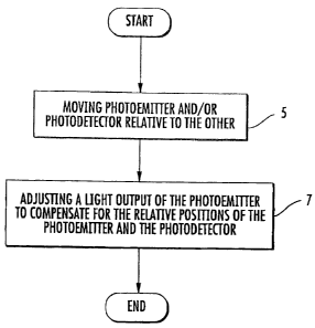
[0012] Figure 1 is a flow chart illustrating operations according to some
embodiments of the present invention.
[0013] Figure 2 is a perspective view of a pharmaceutical tablet dispensing
system
including a sensor system according to some embodiments of the present
invention.
[0014] Figure 3 is a cutaway view of the tablet dispensing system of Figure 2
illustrating a container dispensing station, a labeling carrier, a dispensing
carrier, and a
closure dispensing station thereof.
[0015] Figure 4 is a front, left perspective view of a dispensing bin
according to
some embodiments of the present invention forming a part of the tablet
dispensingsystem of
Figure 2.
" [0016] Figure 5 is a front, right perspective view of the dispensing bin of
Figure 4.
[0017] =Figure 6 is a cross-sectional view of the bin of Figure 4.
[0018] Figure 7 is a cross-sectional=view of the bin-of Figure 4 wherein
tablets
contained therein are being agitated and dispensed in a forward or dispensing
direction.
[0019] Figure 8 is a cross-sectional view of the bin of Figure 4 wherein a
tablet is =
=
being returned to a hopper of the bin in a reverse direction.
[0020] Figure 9. is a front, right perspective view of an adjustable
dispensing channel
subassembly forming a part of the bin of Figure 4.
[0021] Figure 10 is an enlarged, fragmentary, front end view of the bin of
Figure 4
3c
CA 02798014 2012-12-07
WO 2008/143760 PCT/US2008/005441
with a nozzle thereof removed, wherein the dispensing channel subassembly
thereof is
positioned in a first position.
[00221 Figure 11 is an enlarged, fragmentary, front end view of the bin of
Figure 4
with the nozzle thereof removed, wherein the dispensing channel subassembly
thereof is
positioned in a second position.
10023] Figure 12 is an enlarged, fragmentary, front end view of the bin of
Figure 4
with the nozzle thereof removed, wherein the dispensing channel subassembly
thereof is
positioned in a third position.
100241 Figures 13 and 14 are diagrams and corresponding photometric plots
illustrating an effect of a relative position between a photoemitter and a
photodetector
according to some embodiments of the present invention.
[00251 Figure 15 is a graph illustrating plots of photodetector signals and
photoemitter outputs during multiple counting sessions according to some
embodiments of
the present invention.
[0026] Figure 16 is a block diagram illustrating a sensor system in a
pharmaceutical
tablet dispensing system according to some embodiments of the present
invention.
[0027) Figure 17 is a schematic front view of the dispensing channel
subassembly of
the bin of Figure 4 with a tablet in the dispensing channel thereof.
[0028] Figure 18 is a partial, schematic front view of a bin according to
further
embodiments of the present invention.
[00291 Figure 19 is a partial, schematic front view of a bin according to
further
embodiments of the present invention.
[0030] Figure 20 is a partial, schematic, side cross-sectional view of a bin
according
to further embodiments of the present invention.
Detailed Description of Embodiments of the Invention
[00311 The present invention now will be described more fully hereinafter with
reference to the accompanying drawings, in which illustrative embodiments of
the invention
are shown. In the drawings, the relative sizes of regions or features may be
exaggerated for
clarity. This invention may, however, be embodied in many different forms and
should not
be construed as limited to the embodiments set forth herein; rather, these
embodiments are
provided so that this disclosure will be thorough and complete, and will fully
convey the
scope of the invention to those skilled in the art.
4
CA 02798014 2012-12-07
WO 2008/143760 PCT/1JS2008/005441
[0032] It will be understood that when an element is referred to as being
"coupled" or
"connected" to another element, it can be directly coupled or connected to the
other element
or intervening elements may also be present. In contrast, when an element is
referred to as
being "directly coupled" or "directly connected" to another element, there are
no intervening
elements present. Like numbers refer to like elements throughout.
[0033] In addition, spatially relative terms, such as "under", "below",
"lower",
"over", "upper" and the like, may be used herein for ease of description to
describe one
element or feature's relationship to another element(s) or feature(s) as
illustrated in the
figures. It will be understood that the spatially relative terms are intended
to encompass
different orientations of the device in use or operation in addition to the
orientation depicted
in the figures. For example, if the device in the figures is turned over,
elements described as
"under" or "beneath" other elements or features would then be oriented "over"
the other
elements or features. Thus, the exemplary term "under" can encompass both an
orientation of
over and under. The device may be otherwise oriented (rotated 90 degrees or at
other
orientations) and the spatially relative descriptors used herein interpreted
accordingly.
[0034] The terminology used herein is for the purpose of describing particular
embodiments only and is not intended to be limiting of the invention. As used
herein, the
singular forms "a", "an" and "the" are intended to include the plural forms as
well, unless the
context clearly indicates otherwise. It will be further understood that the
terms "comprises"
and/or "comprising," when used in this specification, specify the presence of
stated features,
integers, steps, operations, elements, and/or components, but do not preclude
the presence or
addition of one or more other features, integers, steps, operations, elements,
components,
and/or groups thereof. = As used herein the expression "and/or" includes any
and all
combinations of one or more of the associated listed items.
[0035] Unless otherwise defined, all terms (including technical and scientific
terms)
used herein have the same meaning as commonly understood by one of ordinary
skill in the
art to which this invention belongs. It will be further understood that terms,
such as those
defined in commonly used dictionaries, should be interpreted as having a
meaning that is =
consistent with their meaning in the context of the relevant art and will not
be interpreted in
an idealized or overly formal sense unless expressly so defined herein.
[0036] As used herein, "transverse" means across and nonparallel to a related
axis,
direction or the like. For example, an axis that is referred to as transverse
to another axis
extends across and at an angle with respect to the other axis. Transverse can
include
CA 02798014 2012-12-07
WO 2008/143760 PCT/US2008/005441
perpendicular, but is not limited thereto.
[0037] In accordance with embodiments of the present invention, apparatus and
methods are provided for dispensing solid articles. According to some
embodiments, the solid
articles are solid pharmaceutical articles. In particular, such methods and
apparatus may be used
to dispense pharmaceutical pills or tablets.
10038] According to embodiments of the present invention, an apparatus for
dispensing
and detecting solid articles, such as pharmaceutical articles, includes a
housing that defines a
dispensing channel. A radiation detector (e.g., a photodetector) and a
radiation emitter (e.g., a
photoemitter) are positioned along the dispensing channel. The radiation
emitter directs
radiation (e.g., light) across the channel and onto the radiation detector,
which is operative to
generate detector signals proportional to the received radiation. The
radiation detector is offset
from the radiation emitter.
[0039] Apparatus as described according to embodiments of the present
invention can
provide more consistent and reliable detection of articles passing through the
dispensing
channel. More particularly, the offset between the radiation detector and the
radiation emitter
may provide a sensing area having a location and/or geometry relative to the
geometry of the
dispensing channel that serves to reduce or minimize the size and/or presence
of sensing blind
spots. As used herein, sensing area blind spot refers to a position or region
of the lateral cross-
section of the dispensing channel that is outside of the effective sensing
area cooperatively
defmed by the radiation detector and the radiation emitter. In practice, blind
spots of sufficient
size and shape may permit pharmaceutical articles (or fragments thereof) to
pass by the radiation
detector without intersecting (at all or sufficiently) the sensing area to
occlude the radiation
directed from the radiation emitter to the radiation detector.
[0040] With reference to Figure 1, operations according to further embodiments
of the
present invention use an apparatus including a sensor system that includes a
radiation detector
and a radiation emitter configured to direct light onto the radiation
detector, the radiation
detector being operative to generate detector signals proportional to the
light received thereby.
The method includes moving the radiation emitter and/or the radiation detector
relative to the
other (Block 5). According to some embodiments, the method includes adjusting
a light output
of the radiation emitter to compensate for the relative positions of the
radiation emitter and the
radiation detector (Block 7). According to some embodiments, the method
includes adjusting
the radiation output of the radiation emitter to compensate for a change in
the amount of
radiation incident on the radiation detector from the radiation emitter caused
by moving the
6
CA 02798014 2012-12-07
WO 2008/143760 PCTIUS2008/005441
radiation emitter and/or the radiation detector relative to the other.
[0041] According to some embodiments, the radiation emitter is a photoemitter,
the
-radiation detector is a photodetector, and the radiation is light.
[0042] According to some embodiments, the radiation detector and the radiation
emitter are mounted on different respective walls defining a dispensing
channel and one or both
of the respective walls are relatively moved to change a dimension of the
dispensing channel,
thereby relatively moving the radiation detector and/or the radiation emitter.
= [0043] Methods and apparatus of the present invention may provide
improved
flexibility in the arrangement and range of movement of components defining a
dispensing=
channel for directing pharmaceutical articles. The radiation detector and
radiation emitter may
be mounted on movable walls defining the dispensing channel to provide better
and more
consistent positioning with respect to the passing articles. By compensating
for variation in
= the amount of radiation received=by the radiation detector from the
radiation emitter,
inconsistencies and/or degradation in detection performance caused by altering
the geometry
or relative positions of the radiation detector and the radiation emitter to
adjust the dispensing
channel dimensions can be prevented or reduced. =
=
[0044] A dispensing system according to embodiments of the present invention
and =
that can carry out the foregoing methods is illustrated in Figures 2-12 and
designated broadly
therein at 40 (Figures 2 and 3). The dispensing system 40 includes a sensor
system 102
(Figure 6) according to some embodiments of the present invention. The
dispensing system
40 includes a support frame 44 for the mounting of its various components.
Those skilled in
this art will recognize that the frame 44 illustrated herein is exemplary and
can take many
configurations that would be suitable for use with the present invention. The
frame 44
provides a strong, rigid foundation to which other components can be attached
at desired
locations, and other frame forms able to serve this purpose may also be
acceptable for use
with this invention.
[0045] The system 40 generally includes as operative stations a controller
(represented
herein by a graphical user interface 42), a container dispensing station 58, a
labeling station 60,
a tablet dispensing station 62, a closure dispensing station 64, and an
offloading station 66. In
the illustrated embodiment, containers, tablets and closures are moved between
these stations
with a dispensing carrier 70; however, in some embodiments, multiple carriers
are employed.
The dispensing carrier 70 has the capability of moving the container to
designated locations
within the cavity 45 of the frame 44. Except as discussed herein with regard
to the dispensing
7
CA 02798014 2012-12-07
77203-151D
station 62, each of the operative stations and the conveying devices may be of
any suitable =
construction such as those described in detail in U.S Patent No. 6,971,541 to
Williams et al.
and/or U.S. Patent Publication No. US-2006-0241807-Al.
[00461 The controller 42 controls the operation of the remainder of the system
40. In
some embodiments, the controller 42 will be operatively connected with an
external device,
such as a personal or mainframe computer, that provides input information
regarding
prescriptions. In other embodiments, the controller 42 may be a stand-alone
computer that
directly receives manual input from a pharmacist or other operator. An
exemplary controller is
a conventional microprocessor-based personal computer.
[0047] In operation, the controller 42 signals the container dispensing
station 58 that
a container of a specified size is desired. In response, the container
dispensing station 58
delivers a container for retrieval by the carrier 70. From the container
dispensing station 58,
the container is moved to the labeling station 60 by the carrier 70. The
labeling station 60
includes a printer that is controlled by the controller 42. The printer prints
and presents an
adhesive label that is affixed to the container.
[00481 Filling of labeled containers with tablets is carried out by the tablet
= dispensing station 62. The tablet dispensing station 62 comprises a
plurality of tablet
dispensing bin assemblies or bins 100 (described in more detail below), each
of which holds a
= bulk supply of individual tablets (typically the bins 100 will hold
different tablets). Referring
to Figures 2 and 6, the dispensing bins 100, which may be substantially
identical in size and
configuration, are organized in an array mounted on the rails of the frame 44.
Each
dispensing bin 100 has a dispensing passage or channel 120 with an outlet 124
that faces
generally in the same direction to create an access region for the dispensing
carrier 70. The
identity of the tablets in each bin is known by the controller 42, which can
direct the
dispensing carrier 70 to transport the container to the proper bin 100. In
some embodiments,
the bins 100 may be labeled with a bar code or other indicia to allow the
dispensing carrier 70
to confirm that it has arrived at the proper bin 100.
[0049] The dispensing bins 100 are configured to singulate, count, and
dispense the
tablets contained therein, with the operation of the bins 100 and the counting
of the tablets
being controlled by the controller 42. Some embodiments may employ the
controller 42 as
the device which monitors the locations and contents of the bins 100; others
may employ the
8
CA 02798014 2012-12-07
77203-151D
controller 42 to monitor the locations of the bins, with the bins 100
including indicia (such as
a bar code or electronic transmitter) to identify the contents to the
controller 42. In still other
embodiments, the bins 100 may generate and provide location and content
information to the
controller 42, with the result that the bins 100 may be moved to different
positions on the
frame 44 without the need for manual modification of the controller 42 e., the
bins 100 will
update the controller 42 automatically).
[0050] Any of a number of dispensing units that singulate and count.discrete
objects
may be employed if suitably modified to include the inventive aspects
disclbsed herein. In
particular, dispensing units that rely upon targeted air flow and a
singulating nozzle assembly
may be used, such as the devices described in U.S. Patent No. 6,631,826 to
Pollard et al., U.S.
Patent Publication No. US-2006-0241807-A1, U.S. Patent Application Serial No.
11/750,710,
and/or U.S. Patent Application Serial No. 11/834,936. Bins of this variety may
also
include additional features such as those described below.
[0051] After the container is desirably filled by the tablet dispensing
station 62, the
dispensing carrier 70 moves the filled container to the closure dispensing
station 64. The
closure dispensing station 64 may house a bulk supply of closures and dispense
and secure
them onto a filled container. The dispensing carrier 70 then moves to the
closed container,
grasps it, and moves it to the offloading station 66.
100521 Turning to the bins 100 in more detail, an exemplary bin 100 is shown
in
more detail in Figures 4-12. The bin 100 includes a housing 110 having a
hopper portion
112 and a nozzle 114. The bin 100 is fluidly connected with a pressurized gas
source 136
=
(Figure 7) as discussed in more detail below.
[0053] Referring to Figure 6, the hopper portion 112 defines a hopper chamber
111
that can be filled with tablets T. The bin 100 can be filled or replenished
with tablets through
an opening located at the upper rear portion of the bin 100. The opening is
selectively
accessible via a pivoting door 132, for example.
[0054] The tablets T can be dispensed one at a time into the container C
(Figure 7)
through the dispensing channel 120. The dispensing channel 120 has an inlet
122 adjacent
and fluidly connecting the channel 120 to the hopper chamber 111. The
dispensing channel
120 includes the outlet 124 downstream from and opposite the inlet 122 and
through which
tablets may exit to be dispensed into the container C. The bin 100 defines a
tablet dispensing
9
CA 02798014 2012-12-07
WO 2008/143760 PCT/US2008/005441
path from the inlet 122, through the dispensing channel 120, through the
outlet 124, and
through the nozzle 114.
[0055] The hopper portion 112 has a bottom wall defining a floor 150. The
floor
150 has a sloped rear portion that slopes downwardly toward the inlet 122. The
floor 150
also has a funnel-shaped front portion. A front agitation port or outlet 152
and a rear
agitation port or outlet 154 are provided in the floor 150. As discussed
below, air or other
pressurized gas can be flowed through the outlets 152, 154 and into the hopper
chamber 111
to agitate the tablets T contained therein.
[0056] A front partition or divider wall 156 extends through the hopper
chamber 111
and forms a gap or choke point between the lower edge of the wall 156 and the
floor 150.
According to some embodiments, the choke point has a gap spacing or height
from the floor
150 of between about 0.25 and 0.75 inch. The position of the wall 156, and
thereby the gap
spacing, may be selectively adjusted using an adjustment mechanism.
[0057] A rear partition or divider wall 158 extends through the hopper chamber
111
and forms a gap or choke point between the lower edge of the wall 158 and the
floor 150.
According to some embodiments, the choke point has a gap spacing or height
from the floor
150 of between about 0.6 and 1 inch. The position of the wall 158, and thereby
the gap
spacing, may be selectively adjusted using an adjustment mechanism. According
to some
embodiments, the rear divider wall 158 forms an angle of at least about 30
degrees with
respect to horizontal and, according to some embodiments, between about 30 and
45 degrees
with respect to horizontal.
[0058] The front divider wall 156 and rear divider wall 158 divide the hopper
chamber 111 into subchambers or regions. More particularly and referring to
Figure 6, a
front region or subchamber 111A is defined between the divider wall 156 and
the inlet 122,
an intermediate region or subchamber 111B is defined between the front divider
wall 156 and
the rear divider wall 158, and a rear region or subchamber 111C is defined
between the rear
divider wall 158 and the rear wall of the bin 100.
[0059] The housing 110 further includes a high pressure supply port or nozzle
134.
In use, the pressurized gas source 136 (Figure 7) is fluidly connected to the
high pressure
nozzle 134 via a manifold, fitting, flexible or rigid conduit, or the like.
The gas source 136
may include a compressor or a container of compressed gas, for example. The
high pressure
gas source 136 is operative to provide a supply gas flow of a suitable working
gas at a high
CA 02798014 2012-12-07
WO 20081143760 PCT/US2008/005441
pressure to the nozzle 134. According to some embodiments, the supplied gas is
or includes
air. According to some embodiments, the pressure of the supplied gas at the
nozzle 134 is at
least about 10 psi and, according to some embodiments, between about 10 and 60
psi.
[0060] A gas supply passage or conduit fluidly connects the high pressure
nozzle 134
to a forward control valve 142 (Figure 6). Two forward jet supply passages
fluidly connect
the forward control valve 142 to respective forward drive jet apertures or
outlets 146. The
forward jet outlets 146 are positioned and configured to direct air or other
supplied gas into
the dispensing channel 120. A front agitation supply passage fluidly connects
the forward
control valve 142 to a front air amplifier 160. The front air amplifier 160 is
positioned and
= configured to direct air or other supplied gas into the hopper chamber
111 through the front
agitation outlet 152. The forward control valve 142 is operable to control
airflow to the
forward jet outlets 146 and the front air amplifier 160.
[0061] A further gas supply passage or conduit fluidly connects the high
pressure
nozzle 134 to a reverse control valve 144 (Figure 6). A reverse jet supply
passage fluidly
connects the reverse control valve 144 to a reverse drive jet aperture or
outlet 148. The
reverse jet outlet 148 is positioned and configured to direct air or other
supplied gas into the
dispensing channel 120. A rear agitation supply passage fluidly connects the
reverse control
valve 144 to a rear air amplifier 162. The rear air amplifier 162 is
positioned and configured
to direct air or other supplied gas into the hopper chamber 111 through the
rear agitation
outlet 154. The reverse control valve 144 is operable to control airflow to
the reverse jet
outlet 148 and the rear air amplifier 162.
[0062] In use, the air amplifiers 160, 162 can be used to convert a supplied
pressurized gas flow having a given pressure, velocity and mass flow rate into
an exiting or
output air flow having a comparatively lower pressure, higher velocity, and
higher mass flow
rate. According to some embodiments, the air amplifiers 160, 162 utilize the
Coanda effect.
The outlets of the air amplifiers 160, 162 are positioned in or adjacent the
agitation outlets
152, 154, respectively, so that the exit gas flow enters the hopper chamber
111 through the
agitation outlets 152, 154. The air amplifiers 160, 162 may be constructed
and/or operate in
the manner disclosed in U.S. Patent Application Serial No. 11/750,710, the
disclosure of
which is incorporated herein by reference. Each of the air amplifiers 160, 162
may be secured
to the housing 110.
[0063] According to some embodiments and as illustrated, the drive jet outlets
146,
11
CA 02798014 2012-12-07
WO 2008/143760 PCT/US2008/005441
148 and the agitation outlets 152, 154 are fluidly connected to the
pressurized gas source 136
via the same intake (i.e., the nozzle 134). According to some embodiments, a
single gas
source is used to supply all drive jet outlets and agitation outlets.
According to some
embodiments, the pressure of the gas supplied to each air amplifier 160, 162
is substantially
the same as the pressure of the gas supplied to each drive jet outlet 146,
148.
[0064] Alternative mechanisms may be used to provide the agitation gas flows
discussed herein. For example, the system 40 may provide agitation flow using
a separate
low pressure manifold as disclosed in U.S. Patent Publication No. US-2006-
0241807-A1.
[0065] With reference to Figures 4, 5, 7 and 9-12, the bin 100 further
includes an
= adjustable dispensing channel subassembly 170. The subassembly 170
includes a fixed side
wall 117, a ceiling member 172, a floor member 174, a follower side wall 176,
a dispensing
channel height adjustment mechanism 180, and a dispensing channel width
adjustment
mechanism 182.
[0066] The fixed side wall 117 is fixed with respect to and may be secured to
or
integrally formed with the housing 110. The jets 146, 148 are formed in the
fixed side wall
117.
[0067] The floor member 174 includes a floor wall 174A. The floor member 174
is
movable (e.g., slidable) left and right along an axis W-W relative to the
fixed side wall 117.
The floor wall 174A can be selectively moved relative to the fixed side wall
117 and set using
the adjustment mechanism 182. The follower side wall 176 slides left and right
with the floor
wall 174A so that the lateral spacing between the follower side wall 176 and
the fixed side
wall 117 can be changed and set using the adjustment mechanism 182.
Photoemitter mount
bores 174C, 174D (Figure 7) are defined in the floor wall 174A.
[0068] The ceiling member 172 includes a ceiling wall 172A and a side wall
172B.
The ceiling member 172 is movable (e.g., slidable) up and down along an axis H-
H relative
to the fixed side wall 117 and the floor wall 174A. The heightwise spacing
between the
ceiling wall 172A and the floor wall 174A can be selectively changed and set
using the
adjustment mechanism 180. The follower side wall 176 slides up and down
relative to the
floor member 174 to accommodate repositioning of the ceiling member 172.
Photodetector
mount bores 172C, 172D (Figure 7) are defined in the ceiling wall 172A.
[0069] As illustrated, the adjustment mechanisms 180, 182 each comprise a
thumbscrew adjuster 180A, 182A rotatably fixed in the housing 110 and
operatively engaging
12
CA 02798014 2012-12-07
77203-151D
threaded bores of the ceiling member 172 and the floor member 174,
respectively. However,
other types of adjustment mechanisms may be used.
[0070] The fixed side wall 117, the ceiling wall 172A, the floor wall 174A,
and the
follower side wall 176 together define the dispensing channel 120, the inlet
122, and the
outlet 124. The heightwise and widthwise dimensions of the dispensing channel
120, the
inlet 122, and the outlet 124 can be selectively configured using the
adjustment mechanisms
180, 182. =
[0071] With reference to Figure 6, the sensor system 102 includes an exit
photoemitter 80, an exit photosensor or photodetector 82, an entrance
photoemitter 84, an
entrance photosensor or photodetector. 86, the controller 42, and an emitter
driver operative to
monitor flow of tablets T through the dispensing channel 120. The photoemitter
80 and the
photosensor 82 may cooperate as a first sensor pair and the photoemitter 84
and the
photosensor 86 may cooperate as a second sensor pair. Additionally, the first
and second
sensor pairs may be cooperatively used or monitored as disclosed in U.S.
Patent Application
Serial No. 11/834,936.
[0072] The photodetector 82 is mounted in the bore 172C (Figure 7) of the
ceiling
wall 172A for movement with the wall 172A. The photoemitter 80 is mounted in
the bore
174C (Figure 7) of the floor wall 174A for movement with the wall 174A. The
photodetector 82 and the photoemitter 80 are each positioned along and face
the dispensing
channel 120. According to some embodiments, the photodetector 82 and the
photoemitter 80
are each positioned proximate (and, in some embodiments, at, in or immediately
adjacent) the
outlet 124.
[0073] The photodetector 86 is mounted in the bore 172D of the ceiling wall
172A
for movement with the wall 172A. The photoemitter 84 is mounted in the bore
174D of the
floor wall 174A for movement with the wall 174A. The photodetector 86 and the
photoemitter 84 are each positioned along and face the dispensing channel 120.
According to
some embodiments, the photodetector 86 and the photoemitter 84 are each
positioned
proximate (and, in some embodiments, at, in or immediately adjacent) the inlet
122.
[0074] According to some embodiments, the photoemitters 80, 84 are
photoelectric
emitters and the photodetectors 82, 86 are photoelectric sensors. According to
some
embodiments, the photoemitters 80, 84 are infrared (IR) emitters and the
photodetectors 82,
86 are IR photosensors. According to some embodiments, the photoemitters 80,
84 are ultra-
13
CA 02798014 2012-12-07
WO 2008/143760 PCIMS2008/005441
violet (UV) emitters and the photodetectors 82, 86 are UV photodetectors.
According to
some embodiments, the components 80, 82, 84, 86 may each include both a
photoemitter and
a photodetector, whereby the components 80, 82, 84, 86 may each serve as an
emitter and a
sensor, each configured to emit toward and receive from the other in its
sensor pair.
According to some embodiments, the components 80, 84 may each be replaced with
a
retroreflective photoemitter/photodetector device and the components 82, 86
may each be a
cooperating reflector. Other combinations and configurations including a
photoemitter and
an associated photodetector may be employed. For the purpose of explanation,
the illustrated
embodiment will be described with only the components 82, 86 being a
photodetector (i.e.,
the photodetectors 82, 86 receive photoemissions from the photoemitters 80,
84,
respectively).
[0075] According to still further embodiments, the photoemitters 80, 84 and
the
photodetectors 82, 86 may be radiation emitters and radiation detectors of
other suitable types
that emit and detect corresponding radiation. Other suitable types of
emitter/detector pairs
may include ultrasonic emitters/detectors or electric field (e-field)
emitters/detectors.
[0076] The photodetectors 82, 86 are configured and positioned to detect the
tablets
T as they pass through the dispensing channel 120. The photodetectors 82, 86
are configured
to generate detector signals that are proportional to the light received
thereby. The
photoemitter 80 is positioned and configured to generate light that is
directed toward the
photodetector 82 across the dispensing pathway of the tablets T. Similarly,
the photoemitter
84 is positioned and configured to generate light that is directed toward the
photodetector 86
across the dispensing pathway of the tablets T. In this manner, when a tablet
T interrupts the
light transmitted from the photoemitter 80, 84 to the photodetector 82, 86,
the detector signal
will change based on the reduced light being received at the respective
photodetector 82, 86.
[0077] The photoemitters 80, 84 and the photodetectors 82, 86 are operably
connected to associated sensor receiver/processor electronics. The
photoemitter 80 and the
photodetector 82 may be electrically connected to an associated controller by
respective lead
wires 83 (Figure 6; lead wires for the photoemitters 80, 84 not shown).
According to some
embodiments, the associated controller is or includes the controller 42, any
intervening
circuits, and/or a circuit board mounted on and/or dedicated to the bin 100.
[0078] According to some embodiments, the controller 42 uses detection signals
from one or both of the photodetectors 82, 86 to count the dispensed tablets,
to assess a tablet
14
CA 02798014 2012-12-07
WO 2008/143760 PCIMS2008/005441
or tablets, and/or to determine conditions or performance in tablet
dispensing. In some cases,
the sensor system 102 operates the valves 142, 146 or other devices in
response to identified
or determined count, conditions or performance in dispensing.
[0011 [00791 Exemplary operation of the dispensing system 40 will
now be
described. The bin 100 is filled with tablets T to be dispensed. The tablets T
may initially be
at rest. At this time, the valves 142, 144 are closed so that no gas flow is
provided through
the jet outlets 146, 148 or the agitation outlets 152, 154.
10080] If necessary, the adjustable dispensing channel subassembly 170 is
suitably
adjusted using the adjusters 180, 182 to provide the dispensing channel 120
and/or the inlet
122 with the appropriate dimensions for singulating the intended tablets T.
[0081] When is it desired to dispense the tablets T to fill the container C,
the
dispensing canier 70, directed by the controller 42, moves the container C to
the exit port of
the nozzle 114 of the selected dispensing bin 100. The controller 42 signals
the forward
valve 142 to open (while the reverse valve 144 remains closed). The opened
valve 142
permits the pressurized gas from the gas source 136 to flow through the gas
supply passages
and out through the forward drive jet outlets 146. The pressurized flow from
the jet outlets
146 creates high velocity gas jets that generate suction that causes a forward
flow FF of high
pressure, high velocity air to be drawn outwardly through the dispensing
channel 120 (Figure
7). Tablets T are oriented into a preferred orientation by the shape of the
inlet 122 to the
dispensing channel 120 and dispensed into the container C through the
dispensing channel
120 and the outlet 124 under the force of the forward flow FF. The
photodetectors 82, 86
detect the tablets T as they pass through respective predetermined points in
the dispensing
channel 120.
[0082] The opening of the valve 142 also simultaneously permits the
pressurized
supply gas from the gas source 136 to flow through the front air amplifier 160
and out
through the front agitation outlet 152 as an agitation air flow having a
relatively low velocity
and high mass flow rate as compared to the gas flow from the jet outlets 146.
The front
agitation air flow flows through and lofts or otherwise displaces (i.e.,
agitates) the tablets T in
the front subchamber 111A proximate the inlet 122. This agitation of the
tablets T helps to
orient the tablets T for singulated entry into the dispensing channel 120 and
to prevent tablet
jams. According to some embodiments, the forward jet gas flows and the front
agitation flow
are provided simultaneously.
CA 02798014 2012-12-07
WO 2008/143760 PCT/US2008/005441
[0083] Once dispensing is complete (i.e., a predetermined number of tablets
has been
dispensed and counted), the controller 42 activates the forward valve 142 to
close and the
reverse valve 144 to open. The opened valve 144 permits the pressurized gas
from the gas
source 136 to flow out through the reverse drive jet outlet 148. The
pressurized flow from the
jet outlet 148 creates a high velocity gas jet that generates suction that
causes a reverse (i.e.,
rearward) flow FR of high pressure air to be drawn inwardly through the
dispensing channel
120 toward the chamber 111. In this manner, the airflow is reversed and any
tablets T
remaining in the channel 120 are returned to the chamber 111 under the force
of the reverse
flow (Figure 8).
[0084] The opening of the valve 144 also simultaneously permits the
pressurized
supply gas from the gas source 136 to flow through the rear air amplifier 160
and out through
the rear agitation outlet 154 as a rear agitation air flow which has a
relatively low velocity and
high mass flow rate as compared-to the gas flow from the jet outlet 148. The
rear agitation air
flow flows through and lofts or otherwise displaces (i.e., agitates) the
tablets T in the front
subchamber 111A and/or the intermediate subchamber 111B proximate the choke
point
between the partition wall 156 and the floor 150. This agitation of the
tablets T helps to
loosen the tablets T to permit return of the tablets T and to prevent or break
tablet jams.
According to some embodiments, the reverse jet gas flow and the rear agitation
flow are
provided simultaneously. According to some embodiments, the reverse valve 144
is opened
and then closed after a relatively short period to provide the reverse flow FR
and the rear
agitation flow as short bursts.
[0085] During a dispensing cycle (i.e., when the forward flow FF is being
generated), the controller 42 may determine that a tablet jarn condition is or
may be present.
A tablet jam is a condition wherein one or more tablets are caught up in the
bin 100 such that
tablets T will not feed into or through the dispensing channel 120 under the
pass of the
forward flow FF. Tablets may form a jam at the nozzle inlet 122, one of the
choke points or
elsewhere so that no tablets are sensed passing through the dispensing passage
120 for a
prescribed period of time while the forward air flow FF is being generated.
When a tablet
jam is identified by the controller 42, the controller 42 will issue a "jam
clear" or "backjet" by
closing the forward valve 142 and opening the reverse valve 144 as described
above for
generating the air flow FR and the rear agitation flow to clear a perceived
tablet jam. These
air flows may serve to dislodge any such jams as well as to loosen the tablets
in the
16
CA 02798014 2012-12-07
= WO
2008/143760 = PCTTUS2008/005441
subchamber 111C.
100861 While, in the foregoing description, the controller 42 controls the
valves 142,
146, the valves 142, 146 may alternatively be controlled by a local controller
unique to each
bin 100.
[0087] Typically, an operator will request that a desired number of tablets be
dispensed ("the requested count"). The sensor system 102 detects the tablets T
as they pass
through predetermined points in the dispensing channel 120, as discussed in
more detail
below. The controller 42 uses the detection signals from the photodetector 82
and/or the
photodetector 86 to monitor and maintain a registered count of the tablets T
dispensed ("the
system count"). When the system count matches the requested count; the
controller 42 will
deem the dispensing complete and cease dispensing of the tablets T. If the
controller
miscounts the tablets actually dispensed, there will be a mismatch between the
system count
and the final actual count (and, therefore, the requested count).
[0088] In use, the operator may adjust or readjust the dimensions of the
dispensing
channel 120 by moving One or both of the walls 1724, 176 relative to one
another using the
adjustment mechanisms 180, 182. Typically, the operator will make such an
adjustment as
part of the initial setup procedure when installing the bin 100 in the
dispensing system 40.
The adjustable dispensing channel subassembly 170 permits the dispensing
channel 120 to be
sized and shaped to complement tablets T of different dimensions within a
range of
dimensions. Thus, it is not necessary to preconfigure the bin 100 for a
specific tablet size;
rather, the bin 100 can be reconfigured by the operator to fit the intended
tablet size.
[0089] In some cases, the operator may only adjust the dispensing channel
subassembly 170 once, namely, from its factory settings to the settings
appropriate for the
tablets being dispensed from the bin. For example, only one adjustment may
ever be needed
where the bin 100 is indefinitely or permanently dedicated to dispensing a
particular tablet
size and/or shape.
[0090] In some cases, the operator may make such adjustments to the channel
120
between dispensing sessions in order to size the cross-section of the
dispensing channel 120
to complement the size and configuration of the tablets to be dispensed next.
[0091] However, by readjusting the walls 172A, 176 (whether during initial
setup or
between counting sessions), the operator also alters the geometry between the
photoemitters
80, 84 and their respective photodetectors 82, 86 and thereby their
cooperative photoelectric
17
CA 02798014 2012-12-07
WO 2008/143760
PCT/I1S2008/005441
performance and detection characteristics. For example, raising and lowering
the ceiling wall
172A increases and decreases, respectively, the distance between the
photoemitter 80 and the
photodetector 82 and between the photoemitter 84 and the photodetector 86
parallel to the Y-
axis. Moving the wall 176 left and right also moves the floor wall 174A left
and right and
thereby changes the distance of offset between the photoemitter SO and the
photodetector 82
and between the photoemitter 84 and the photodetector 86 along or parallel to
the X-axis.
Without compensation, these positional variations may change the degree of
overlap between
the emission field of the photoemitter 80 and the reception field of the
photodetector 82 (and,
likewise, the degree of overlap between the emission field of the photoemitter
84 and the
reception field of the photodetector 86), thereby creating corresponding
variations in the
sensitivity of the sensor system 102. For clarity, the construction and
operation of the system
40 will be described with regard to the photoemitter 80 and the photodetector
82. It will be
appreciated that, according to some embodiments, this description likewise
applies to the
photoemitter 84 and the photodetector 86.
= [0092] The foregoing effect will now be illustrated with reference to
Figures 10 and
=
11, which are front end views (with the nozzle 14 removed) of the adjustable
dispensing
channel subassembly 170 in two different positions to provide respective
configurations of
the dispensing channel 120 having different dimensions. Figures 13 and 14 are
diagrams of
photometric plots corresponding to the positions of Figures 10 and 11,
respectively, and
illustrating an effect of a relative position (and variation therein) between
the photoemitter 80
and the photodetector 82 along the.X-axis. Figures 10 and 13 illustrate the
dispensing
channel 120 configured such that the photoemitter 80 is substantially aligned
with the
photodetector 82 along an axis parallel to the Y-axis (i.e., located at
substantially the same
position along the X-axis). In contrast, Figures 11 and 14 illustrate a
dispensing channel
configuration wherein the photoemitter 80 and the photodetector 82 are offset
or skewed from
one another along the X-axis.
[0093] As illustrated in Figure 13, the photoemitter 80 emits light to provide
an
= emission field that may be characterized by an emission cone 243. The
intensity of light
transmitted by the photoemitter 80 in the emission field may have less than
uniform emission
characteristics e., intensity) throughout the range of the emission cone 243.
For example,
the emission cone 243 may have emission characteristics that correspond to an
emission
curve 248 as shown in Figure 13. In the illustrative emission curve 248,
the.intensity of the
18
CA 02798014 2012-12-07
WO 2008/143760 PCT/US2008/005441
emitted light diminishes as the angle within the emission cone 243 increases.
[00941 Similarly, the photodetector 82 defines a reception field (which may be
characterized as a reception cone 245) from which it can operably receive
ambient light. The
reception cone 245 has a reception curve 250 similar to that of the emission
curve 248. In the
illustrated embodiment, the peaks of the emission curve 248 and the reception
curve 250
occur near the centers of the emission cone 243 and the reception cone 245,
respectively. In
such embodiments, peak reception of emitted light may occur when the
photoemitter 80 is
substantially across from and directed toward the photodetector 82. A peak
reception value
260 of emitted light may be estimated by superimposing the emission curve 248
and the
reception curve 250 at their relative positions and determining an
intersection of the emission
curve 248 and the reception curve 250. Because, in this simplified example,
the emission
curve 248 and the reception curve 250 are substantially similar and the
photoemitter 80 is
directly across from the photodetector 82, the peak reception value 260
coincides with the
maximum values 262 of the emission curve 248 and the reception curve 250. As
illustrated,
the emission cone 243, the reception cone 245, the emission curve 248, and
.the reception
curve 250 are simplified representations and are presented merely by way of
example.
[0095] When the photodetector 82 and the photoemitter 80 are in their
relatively
skewed or offset position as shown in Figure 11, the emission curve 248 and
the reception
curve 250 are superimposed.on one another in their relative positions as
represented in
Figure 14. The point of intersection between the emission curve 248 and the
reception curve
250 represents a new peak reception value 261, which may represent the best
available
received light at the photodetector 82 at the offset positions. Note that the
peak reception
value 261 is substantially less than the maximum values 262 based on the
offset between the
photoemitter 80 and the photodetector 82.
[0096] The peak reception value may also be affected by or vary with the
distance
between the photoernitter 80 and the photodetector 82. For example, the
dispensing channel
subassembly 170 may be further adjusted to move the ceiling wall 172A away
from the floor
wall 174A to assume the geometry between the photoemitter 80 and the
photodetector 82 as
shown in Figure 12. It will be appreciated that various other combinations of
width and
height may be selected for the dispensing channel 120, with corresponding
different
geometries between the photoemitter 80 and the photodetector 82. The spacing
between the
photoemitter 80 and the photodetector 82 may affect both the amount of light
dispersal and
19
CA 02798014 2012-12-07
WO 2008/143760
PCT/US2008/005441
the amount of overlap between the offset photoemitter and photodetector.
[0097] In accordance with some embodiments of the present invention, in order
to
facilitate improved detection of the tablets T, the sensor system 102
accommodates or
compensates for the reduced peak reception value 261 by increasing the output
of the
photoemitter 80. According to some embodiments, the offset positions between
the
photoemitter 80 and the photodetector 82 are compensated for by adjusting
(i.e., increasing or
decreasing) the energy supply to the photoemitter 80 to generate a detector
reference signal
level from the photodetector 82 that is within a prescribed reference level
range. This may be
accomplished by a calibration or recalibration step or process that returns
the photodetector
reference signal to a level within the reference level range (or maintains the
detector reference
signal if already in the reference level range). According to some
embodiments, the
calibration is automatically initiated and executed by the controller 42.
However, the
= calibration step may additionally or alternatively be initiated
manually.=
[0098] With reference to Figure 15, aspects of exemplary Counting Sessions 1-4
are.
schematically illustrated therein. For the purpose of illustration, the
Counting Sessions 1-4= =
will be described as an exemplary series of counting sessions wherein the
dispensing channel
= subassembly 170 is set to different respective configurations. However,
as discussed herein,
= in some cases the subassembly 170 may be set once and the bin 100
used with the =
subassembly 170 at that setting for.multiple, all or an indefinite number of
counting sessions.
Thus, while a series of counting sessions are shown with transitions or
adjustments in
detector signals or emitter outputs therebetween, it should be appreciated
that, in some uses
and some embodiments, the bin 100 may, for example, be set to only one of the
dispensing
channel configurations so that the corresponding Counting Sessions 1-4
represent the
performance or attributes of the sensor system 102 in that setting and the
other illustrated
Counting Sessions 1-4 do not apply (although they may represent the
performance or
attributes of the sensor system 102 if the subassembly 170 had alternatively
been set in such
other configurations).
= [0099] In section (A) of Figure 15, an end view of the configuration of
the walls
172A, 174A (and, therefore, the relative positions of the photoemitter 80 and
the
photodetector 82) are shown for each counting session. Section (B) of Figure
15 is a graph
= showing the reference signal 190 (e.g., the signal in the absence of any
occluding tablet T)
generated by the photodetector 82 without compensation in accordance with the
present
CA 02798014 2012-12-07
WO 2008/143760 PCINS2008/005441
invention (i.e., the light output of the photoemitter 80 is the same during
all of the counting
sessions). Section (C) of Figure 15 is a graph representing the light output
level 192 from the
photoemitter 80 during each counting session and with compensation or
recalibration in
. accordance with embodiments of the present invention. As discussed
herein, the photoemitter
light output may be proportional to a photoemitter energy level supplied to
the photoemitter
80 by an emitter driver. Section (D) of Figure 15 is a graph representing the
reference signal
194 generated by the photodetector 82 during each counting session with
compensation
provided in accordance with embodiments of the present invention (L e., with
the adjustments
to the photoemitter light output as shown in Section (C)).
[01001 With reference to Section (A) and Section (B) of Figure 15, the
detector
=
signal 190 of the photodetector 82 without variation of the photoemitter
output will first be
= described. In Counting Session 1, the photodetector 82 and the
photoemitter 80 are in Y-axis
alignment and relatively close proximity and the detector signal is therefore
relatively high.
In Counting Session 2, the photodetector 82 and the photoemitter 80 are
offset, causing the
detector signal to drop. In Counting Session 3, the photodetector 82 and the
photoemitter 80
remain offset and are also further separated, causing the detector signal to
drop further. In
Counting Session 4, the photodetector 82 and the photoemitter 80 are returned
to alignment
but remain separated, causing the detector signal to be partially restored. In
practice, the
variation in sensitivity as illustrated may present the problems described
hereinabove.
[01011 Referring now to Section (A), Section (C) and Section (D) of Figure 15,
it
=
will be appreciated that a consistent reference signal 194 can be provided
from the
photodetector from counting session to counting session even though the
geometry between
the photodetector 82 and the photoemitter 80 is changed between counting
sessions. In
Counting Session 1, the photoemitter 80 is set to a first output level to
provide the desired
detector signal level 190 from the photodetector 82. When the photodetector 82
and
photoemitter 80 are moved out of alignment for Counting Session 2, the output
of the
photoemitter 80 is increased to compensate and maintain the reference detector
signal from
the photodetector 82 at the same desired level. The output of the photoemitter
80 is likewise
increased and then lowered to compensate for the reconfigurations of the
photodetector 82
and the photoemitter 80 in Counting Sessions 3 and 4, respectively, to
maintain the reference
detector signal from the photodetector 82 at the desired level. While the
recalibrations of the
photoemitter 80 are illustrated in Section (C) as substantially instantaneous,
it will be
21
CA 02798014 2012-12-07
= WO 2008/143760
PCT/US2008/005441
appreciated that some period of transition may occur.
[0102] While the exemplary dispensing channel configurations and sensor system
performance of Figure 15 are discussed with regard to sequential counting
sessions, the
foregoing discussion likewise generally applies in the case where the
dispensing channel 120
is adjusted once (e.g., when the bin is initially installed) and remains in
its initial
configuration throughout and between some or all subsequent counting sessions.
For
example, if the dispensing channel 120 is set to the configuration of Counting
Session 1, 2, 3
or 4, the output level of the photoemitter 80 is set to the corresponding
respective level
indicated in Section (C) so that, regardless of the dispensing channel
configuration setting
selected, substantially the same detector signal level as illustrated in
Section (D) will be
provided. For example, the dispensing channel configuration of Counting
Session 1 may be
an initial factory or optimized setting and the configurations of Counting
Sessions 2, 3 and 4
may be different alternative configurations the operator may select as the
indefinite or
permanent configuration of the dispensing channel 120. In each case, the
emitter output level
is adjusted to compensate for the relative positions of the photoemitter 80
and the
photodetector 82 as indicated in Section (C).
[0103] According to some embodiments, the calibration step is executed only
before =
and/or between counting sessions and not during counting sessions. In this
manner, the
system 40 can compensate for differences or changes in the relative positions
of the
photoemitter 80 and the photodetector 82 while preventing or reducing the
introduction of
undesirable variation in the sensor system parameters. By recalibrating to
restore the
reference signal level to a value within the prescribed reference level range
between counting
sessions, additional resolution based on the stability of the reference signal
level may be
achieved. The additional resolution may facilitate discrimination between
multiple different
system and/or tablet characteristics. For example, tablet profiles and/or
signatures may be
determined and used to detect tablet fragments and/or incorrectly selected
tablets.
Additionally, embodiments providing digital detector signals may facilitate
additional event
= analysis advantages through the use of digital processing techniques.
[0104] Figure 16 is a block diagram schematically illustrating portions of the
sensor
system 102 in accordance with some embodiments of the present invention. The
sensor
system 102 includes an emitter driver 81 configured to provide current to the
photoemitter 80.
The intensity of light emitted by the photoemitter 80 is variable based on the
amount of
current and/or energy level provided by the emitter driver 81. A portion of
the light emitted
22
CA 02798014 2012-12-07
WO 2008/143760 PCT/US2008/005441
by the photoemitter 80 is received by the photodetector 82, which generates a
detector signal
proportional to the amount of light received. The detector signal is received
by the controller
42, which is configured to process the detector signal to determine the
occurrence of an event,
such as a tablet T traversing the dispensing pathway. The controller 42 may
also be
configured to provide control signals to the emitter driver 81. In some
embodiments, emitter
driver 81 and the controller 42 may be employed in an integrated hardware
device. Some
embodiments employ an analog to digital converter (A/D) to convert the
detector signals into
digital detector signals. Although the analog to digital converter may be a
separate
component, in some embodiments, it is integrated into the photodetector 82
ancUor the
= controller 42. =
[0105] As discussed above, operations also may include monitoring the detector
signals from the photodetector 82 to determine a reference signal level. The
reference signal
level may correspond to the amount of light received at the photodetector 82
in the absence of
an article blocking light between the photoemitter 80 and the photodetector
82.
[0106] Event signals may be identified from the photodetector 82 with respect
to a
threshold signal level. For example, where the detector signal value changes
from the
reference signal level to some level below the threshold signal level, an
event signal may be
identified. In some embodiments, the event signals are digitally processed to
detect, count
and/or characterize the articles passed along the dispensing pathway. The
event signals may
be evaluated in terms of signal value and/or signal duration to detect, count
and/or
characterize the articles. =
[0107] Mounting the photoemitter 80, 84 and photodetector 82, 86 of each
sensor
pair for relative movement with adjustment of the adjustable dispensing
channel subassembly
170 may provide significant performance advantages as compared to dispensing
devices
wherein the dispensing channel is adjustable but the photoemitter and the
photodetector are
fixed relative to one another and walls defining the dispensing channel. In
the latter case, the
dispensing channel may be re-configured such that the effective sensing area
of the sensing
pair (i.e., the overlap between the emission cone of the photoemitter 80 and
the reception
cone of the photodetector 82) is off center or otherwise skewed such that a
"blind spot" is
created in the dispensing channel. Tablets or fragments thereof may
undesirably slip through
the blind spot and thereby be dispensed but remain undetected.
[0108] Embodiments of the present invention may reduce or eliminate the
foregoing
23
CA 02798014 2012-12-07
WO 2008/143760
PCTMS2008/005441
risk by offsetting the photodetector 82 from the photoemitter 80. In this way,
the effective
field of view or sensing area of the sensor pair 80, 82 may be extended
transversely to the
dispensing path axis (i.e., the longitudinal axis Z (Figure 9) of the
dispensing channel 120)
across both the width and height of the dispensing channel 120. In this way,
the sensing area
is increased in size and is distributed across the dispensing channel 120 in a
manner that
obviates sensing area blind spots or at least the creation of sensing area
blind spots large
enough to permit a tablet having a prescribed (or greater) size= and shape to
pass therethrough
without occluding the sensor beam. According to some embodiments, the offset
distance
increases as the corresponding dimension of the dispensing channel 120 is
increased by
adjustment of the dispensing channel subassembly 170.
10109] By way of example, the effective sensing areas or beams B1, B2, B3 and
B4
of the photoemitter 80 and the photodetector 82 are illustrated in Figure 15,
Section (A) for
each dispensing channel configuration. Figure 19 is an enlarged view of the
configuration of
Counting Session 2 with a tablet T illustrated passing between the
photoemitter 80 and the
photodetector 82. The photodetector 82 and the photoemitter 80 are positioned
relatively
adjacent diagonally opposed corners of the rectangle defined by the dispensing
channel 120 in
cross-section. The sensing beam B2 therefore extends diagonally across the
dispensing =
charmel 120 (i.e., at an angle with respect to each of the width dimension and
the height
dimension of the dispensing channel 120). As a result, the relative geometries
of the sensing
beam B2 and the dispensing channel 120 ensure that the tablet T will occlude
the beam B2
and be detected.
[0110] Thus, the arrangement in accordance with embodiments of the present
invention adjusts the configuration of the sensor/emitter pair in
correspondence to the
configuration of the dispensing channel 120 to prevent or reduce blind spots.
The reduced
blind spots or increased sensing area may also ensure that a given tablet
occludes the beam
B2 for a greater part of the length of the tablet, thereby providing for an
improved tablet
profile.
= [0111] By contrast, if the photoemitter 80 and the photodetector 82 were
fixed in
relation to one another and the dispensing channel 120 such that, in the
dispensing channel
configuration of Counting Session 2, the photoemitter 80 were positioned
directly below the
=photodetector 82 (L e., on the primary sensing axis Al), the sensing beam
would extend
directly vertically and offset to the left of the center of the dispensing
channel 120. An
24
CA 02798014 2012-12-07
WO 2008/143760 PCT/US2008/005441
enlarged blind spot would thereby be created to the right of the sensor pair
80, 82. The
enlarged blind spot would permit the illustrated tablet to pass the sensing
beam on the right
side of the dispensing channel 120 without occluding the sensing beam and
being properly
detected.
[0112] Referring to Figures 14 and 17, the photodetector 82 has a primary
reception
= axis Al defined as the axis along which the photodetector 82 will have
its peak or maximum
reception sensitivity for any given distance from the photodetector 82.
Similarly, the
photoemitter 80 has a primary emission axis A2 defined as the axis along which
the
photoemitter 80 will have its peak or maximum emission intensity for any given
distance =
from the photoemitter 80. According to some embodiments and as illustrated in
Figure 17,
the primary reception axis A1 is offset from the primary emission axis A2 in
at least some
operational configurations of the adjustable dispensing channel subassembly
170. According
to some embodiments and as shown, the primary reception axis Al is laterally
offset from the
primary emission axis A2 by a distance D3 (L e., offset a distance
perpendicular to the
lengthwise direction of the dispensing path at or proximate the sensor pair
80, 82).
[0113] According to some embodiments and as illustrated by the dispensing
channel
subassembly 170 when configured as shown in Figure 17, the dispensing channel
120 is
collectively defined by a first set of opposed walls 172A, 174A that ere
spaced apart along a
. first axis C1-C1 and a second set of opposed walls 117, 176 that are
spaced apart along a
second axis C2-C2 transverse (in some embodiments, perpendicular, as
illustrated) to the first
axis C1-C1. The photodetector 82 is spaced apart from the photoemitter 80
across the
dispensing channel 120 a first linear distance D1 parallel to the first axis
C1-C1. The
photodetector 82 is offset from the photoemitter a second linear distance D2
parallel to the
second axis C2-C2.
[0114] According to some embodiments, the dispensing channel 120 is
rectangular
in cross-section and the sensing area or beam (e.g., the sensing area 152)
extends diagonally
across all or a part of the dispensing channel 120. In accordance with some
embodiments and
as illustrated, the photodetector 82 and the photoemitter 80 move with their
associated
comers of the dispensing channel 120 so that as the dispensing channel
subassembly 170 is
adjusted, the photodetector 82 and the photoemitter 80 are reconfigured to
adjust the angle
and length of the diagonally extending sensing beam to the new geometry of the
dispensing
channel 120.
CA 02798014 2012-12-07
WO 2008/143760 PCT/US2008/005441
101151 In some embodiments, the dispensing channel 120 cross-sectional area
has a
major dimension (e.g., the width dimension W of Figure 17) on its major axis
C2-C2 and a
smaller minor dimension (e.g., the height dimension H) on its minor axis C1-
C1, and the
sensing area (e.g., the sensing area B2) extends diagonally across the
dispensing channel 120
at an angle with respect to each of the major and minor dimensions. According
to some
embodiments, the major and minor dimensions are perpendicular to one another.
According
to some embodiments, one of the major and minor dimensions is aligned with a
vertical axis
and the other of the major and minor dimensions is aligned with a horizontal
axis.
[0116] With reference to Figure 18, a partial, schematic front view (i.e.,
corresponding to the view of Figure 17) of a bin 300 including an adjustable
dispensing
channel subassembly 370 according to further embodiments of the present
invention is shown
therein. The bin 300 may correspond to (i. e., include the various features,
components and
functionality of) the bin 100 as described herein, except as discussed
hereinbelow. The bin
300 may be used in place of and in the same manner as the bin 100 in the
dispensing system
40. For the purposes of description, components of the bin 300 corresponding
to the
components of the bin 100 are designated with the same numerals as used in
describing and
illustrating the bin 100.
[0117] The adjustable dispensing channel subassembly 370 is constructed in the
same manner as the adjustable dispensing channel subassembly 170 except that
the
photodetector 82 and the photoemitter 80 are not mounted in the walls 172A and
174A for
movement therewith. Instead, the photodetector 82 and the photoemitter 80 are
mounted in
respective opposed, vertically offset ports 114A, 114B in the nozzle 114
(which is shown in
fragmentary view in Figure 18; see also Figure 4, which illustrates potential
locations for the
ports 114A, 114B). According to some embodiments, the photodetector 82 and the
photoemitter 80 are located downstream of, but closely adjacent, the outlet of
the dispensing
channel 120 and at the same axial location along the length of the dispensing
path.
[0118] In the bin 300, the photodetector 82 and the photoemitter 80 are fixed
in
= relation to one another. More particularly, the photodetector 82 and the
photoemitter 80 do
not move with adjustment of the walls 1.17, 172A, 174A, 176 that define the
dispensing
channel 120, but are offset with respect to one another. An effective sensing
area or beam B5
= corresponding to the sensing beams B1, B2, B3, B4 (i.e., the overlap
between the emission
cone of the photoemitter 80 and the reception cone of the photodetector 82)
extends across
26
CA 02798014 2012-12-07
=
WO 2008/143760 PCTFUS2008/005441
the dispensing channel 120 and the dispensing path of the tablets.
[0119] According to some embodiments, the photodetector 82 and the
photoemitter
80 are mounted in diagonal opposition to one another so that the sensing beam
B5 extends
diagonally across the dispensing channel 120. According to some embodiments
and as
shown, the dispensing channel 120 is rectangular in cross-section and the
sensing beam B5
intersects the dispensing channel 120 adjacent the diagonally opposed corners
of the
rectangle.
[0120] According to some embodiments, the primary reception axis A1 of the
photodetector 82 and the primary emission axis A2 of the photoemitter 80 are
offset from one
another a distance D4 transverse (e.g., perpendicular, as shown) to the
lengthwise extent of
the dispensing path.
[0121] With reference to Figure 17, a partial, schematic front view (L e.,
corresponding to the view of Figure 17) of a bin 400 according to still
further embodiments
of the present invention is shown therein. =The bin 400 may correspond to the
bin 100 except
as follows. The bin 400 may be used in place of and in the same manner as the
bin 100 in the
dispensing system 40.
[0122] The bin 400 has a non-adjustable dispensing channel subassembly 470 in
place of the adjustable dispensing channel subassembly 170. The dispensing
channel
subassembly 470 includes relatively fixed walls 472, 474, 476, 478 that define
the dispensing
channel 120. The photodetector 82 and the photoemitter 80 are mounted in
respective ports
in the walls 472 and 474. The sensor pair 80, 82 has an effective sensing area
or beam B6
that extends across the dispensing channel 120 and the path of the tablets.
The photodetector
82 and the photoemitter 80 are offset. The sensing beam B6 extends diagonally
across the
dispensing channel 120 from adjacent respective diagonally opposed corners of
the rectangle
as discussed above with reference to Figure 17 and the bin 100. Likewise, the
primary
reception and emission cones of the sensor pair 80, 82 are offset from one
another a distance
transverse to the lengthwise extent of the dispensing path as discussed above
with regard to
the bin 100.
[0123] With reference to Figure 20, a partial, schematic, side cross-sectional
view
(i.e., corresponding to the view of Figure 6) of a bin 500 according to still
further
embodiments of the present invention is shown therein. The bin 500 may
correspond to the
bin 100 except as follows. The bin 400 may be used in place of and in the same
manner as
27
CA 02798014 2012-12-07
= WO 2008/143760
PCTrUS2008/005441
the bin 100 in the dispensing system 40.
[0124] The bin 500 has a non-adjustable dispensing channel Subassembly 570 in
place of the adjustable dispensing channel subassembly 170. The dispensing
channel
subassembly 570 includes relatively fixed walls 572, 574, 578, and a fixed
side wall (not
shown) opposite the wall 578 that define the dispensing channel 120. Thc
photodetector 82
and the photoemitter 80are mounted in respective ports in the walls 472 and
474. The sensor
pair 80, 82 has an effective sensing area or beam B7 that extends across the
dispensing
channel 120 and the path of the tablets. The photodetector 82 and the
photoemitter 80 are
offset along the dispensing pathway, with the photoemitter 80 nearer the
dispensing channel =
inlet 122 and the photodetector 82 nearer the dispensing channel outlet 124.
The sensing
beam B7 extends diagonally across the dispensing channel 120 along a
lengthwise extent (i.e.,
with respect to the lengthwise axis G-G or the dispensing path) of the
dispensing channel
120. The primary reception and emission cones of the sensor pair 80, 82 are
offset from one
another a distance transverse to the widthwise extent and the heightwise
extent of the
dispensing path. =
[0125] According to further embodiments, the photodetector 82 and the
photoemitter
= 80 of the bin 500 are mounted in relatively movable walls of an
adjustable dispensing channel
subassembly, and the lengthwise offset of the photodetector 82 and the
photoemitter 80 is
adjustable by selectively moving the walls. According to further embodiments,
the
photodetector 82 and the photoemitter 80 of the bin 500 are= also offset from
one another a
distance transverse to the lengthwise extent of the dispensing path as
illustrated with regard to
the bin 400.
[002] [0126] While the sensor system 102 has been described
hereinabove
with regard to the bin 100 and the dispensing system 40, sensor systems
according to
embodiments of the present invention may be used with bins and/or systems of
other types
and configurations. Sensor systems 102 according to embodiments of the present
invention
may include sensor components differently configured than the sensor
components 80, 82, 84,
86.
[0127] While embodiments employing gas flow drive mechanisms are described
herein, other embodiments of the present invention may employ other drive
mechanisms in
place of or in addition to gas flow. For example, the pharmaceutical articles
may be passed in
the forward and/or reverse direction by vibration and/or gravity.
28
CA 02798014 2012-12-07
WO 2008/143760 PC171152008/005441
[01281 The foregoing is illustrative of the present invention and is not to be
construed as limiting thereof. Although a few exemplary embodiments of this
invention has
been described, those skilled in the art will readily appreciate that many
modifications are
possible in the exemplary embodiments without materially departing from the
novel teachings
and advantages of this invention. Accordingly, all such modifications are
intended to be
included within the scope of this invention. Therefore, it is to be understood
that the
foregoing is illustrative of the present invention and is not to be construed
as limited to the
specific embodiments disclosed, and that modifications to the disclosed
embodiments, as well
as other embodiments, are intended to be included within the scope of the
invention.
=
=
29