Note: Descriptions are shown in the official language in which they were submitted.
CA 02798092 2012-10-29
WO 2011/137036 PCT/US2011/033523
IMPLANTABLE DEVICE TO PROTECT TUBING FROM PUNCTURE
BY
CHRISTOPHER R. DEUEL, JASON B. JACQUET, BABAK HONARYAR, AND MARCOS BORRELL
CROSS -REFERENCE
[0001] This application claims the benefit of U.S. Patent
Application Serial Number 12/771,609, filed on April 30, 2010,
the entire disclosure of which is incorporated herein by this
specific reference.
FIELD
[0002] The present invention generally relates to medical
systems and apparatus and uses thereof for treating obesity
and/or obesity-related diseases, and more specifically, relates
to an implantable device used in a medical system to protect
tubing from puncture.
BACKGROUND
[0003] Adjustable gastric banding apparatus have provided an
effective and substantially less invasive alternative to gastric
bypass surgery and other conventional surgical weight loss
procedures. Despite the positive outcomes of invasive weight
loss procedures, such as gastric bypass surgery, it has been
recognized that sustained weight loss can be achieved through a
laparoscopically-placed gastric band, for example, the LAP-BAND
(Allergan, Inc., Irvine, CA) gastric band or the LAP-BAND APO
(Allergan, Inc., Irvine, CA) gastric band. Generally, gastric
bands are placed about the cardia, or upper portion, of a
patient's stomach forming a stoma that restricts food's passage
into a lower portion of the stomach. When the stoma is of an
appropriate size that is restricted by a gastric band, food held
in the upper portion of the stomach provides a feeling of
satiety or fullness that discourages overeating. Unlike gastric
bypass procedures, gastric band apparatus are reversible and
require no permanent modification to the gastrointestinal tract.
CA 02798092 2012-10-29
WO 2011/137036 PCT/US2011/033523
[0004] Certain types of gastric band systems may operate through
a hydraulic force. The size of the band placed around the
stomach may depend on the volume of fluid in the band. An
access port may be used to control the amount of fluid in the
band. The access port may be located below the surface of an
individual's skin. The physician accesses the access port to
either increase or decrease the amount of fluid in the band.
The physician inserts a long hypodermic needle through the
surface of the skin and into the access port. The physician may
then deposit or remove fluid from the system to control
operation of the gastric band. However, the access port may be
under many layers of fat, and may be difficult to locate. If
the physician cannot properly locate the access port, the
physician may improperly insert the hypodermic needle into the
individual's body.
[0005] If the physician improperly inserts the hypodermic needle
into the individual's body, the hypodermic needle may puncture
the tube leading from the access port to the gastric band. The
tube contains fluid that may leak causing the gastric band to
eventually fail. The entire gastric band system may then need
to be removed from the individual's body, or the physician may
need to perform an operation to mend the punctured tube.
SUMMARY
[0006] Generally described herein is an implantable shielding
device that protects tubing used in a gastric band system. A
protective system placed over the tubing may protect the tube
from errant needle sticks.
[0007] In one embodiment, the implantable device comprises an
access port configured to attach to body tissue, a tube coupled
to the access port, and a shielding device coupled to the tube.
The shielding device is positioned adjacent to the access port
and covers the end of the tube coupled to the access port. The
shielding device is made from a puncture resistant material.
2
CA 02798092 2012-10-29
WO 2011/137036 PCT/US2011/033523
The shielding device protects the tube from puncture, by
blocking the movement of a needle directed towards the tube.
[0008] In one embodiment, the shielding device comprises a
plurality of individual shields. Each individual shield may
have a bell-like shape, a cone-like shape, a cylindrical shape,
a bullet-like shape, or a ball and socket shape. The individual
shields are positioned adjacent to each other along the tube.
Each individual shield may be independently moveable to allow
the tube to bend. Portions of adjacent individual shields
overlap each other to assure no portion of the tube is exposed
to an incoming needle. In addition, multiple different shapes
of individual shields may be alternatively placed along the
tube.
[0009] In one embodiment, the shielding device comprises a coil
wrapped around the outer circumference of the tube. The coil is
wrapped such that no portion of the tube is exposed to the
needle. The coil may include a single wire, or multiple wires
wrapped around the tube. In addition, multiple layers of wire
may be wrapped over each other around the tube to further assure
a needle cannot puncture the tube. Furthermore, the coil may
have a size that is small enough to be integrated within the
tube, as an alternative to placing it around the tube. The coil
may be made from metal or a hard plastic or polymer.
[0010] In one embodiment, the shielding device has a flattened
disk-like shape and is coupled to the access port. The
flattened disk extends outward from the access port in a radial
dimension to cover a portion of the tube. The shielding device
may comprise multiple flattened disks extending outward from the
access port, or a half-disk shape extending from the access port
in a direction towards the tube. In addition, the shielding
device may have multiple layers of material pressed together, or
sandwiched together to increase puncture resistance. The
3
CA 02798092 2012-10-29
WO 2011/137036 PCT/US2011/033523
flattened disk may be a flexible disk, made from a flexible
puncture resistant fabric or a hard material such as plastic.
BRIEF DESCRIPTION OF THE DRAWINGS
[0011] FIG. 1 illustrates a gastric band system according to an
embodiment of the present invention.
[0012] FIG. 2 illustrates a perspective view of the inner
diameter of the band corresponding to a decreased volume of
fluid in the gastric band according to an embodiment of the
present invention.
[0013] FIG. 3 illustrates a perspective view of the inner
diameter of the band corresponding to an increased volume of
fluid in the gastric band according to an embodiment of the
present invention.
[0014] FIG. 4 illustrates a perspective view of the gastric band
system removed from an individual's body according to an
embodiment of the present invention.
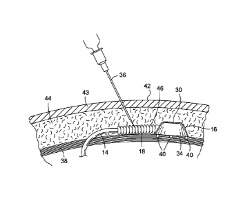
[0015] FIG. 5 illustrates a side, cut-away view of the access
port attached to the muscle wall of an individual according to
an embodiment of the present invention.
[0016] FIG. 6 illustrates a perspective, close-up view of the
shielding device and the access port according to an embodiment
of the present invention.
[0017] FIG. 7 illustrates a side, cut-away view of the shielding
device in operation according to an embodiment of the present
invention.
[0018] FIG. 8 illustrates a side, cross-sectional view of the
shielding device according to an embodiment of the present
invention.
4
CA 02798092 2012-10-29
WO 2011/137036 PCT/US2011/033523
[0019] FIG. 9 illustrates a side, cross-sectional view of the
shielding device according to an embodiment of the present
invention.
[0020] FIG. 10 illustrates a side, cross-sectional view of the
shielding device according to an embodiment of the present
invention.
[0021] FIG. 11 illustrates a side, cross-sectional view of the
shielding device according to an embodiment of the present
invention.
[0022] FIG. 12 illustrates a side, cross-sectional view of the
shielding device according to an embodiment of the present
invention.
[0023] FIG. 13 illustrates a side, cross-sectional view of the
shielding device according to an embodiment of the present
invention.
[0024] FIG. 14 illustrates a side view of the shielding device
according to an embodiment of the present invention.
[0025] FIG. 15 illustrates a side, close-up view of the
shielding device according to an embodiment of the present
invention.
[0026] FIG. 16 illustrates a side, cross-sectional view of the
shielding device according to an embodiment of the present
invention.
[0027] FIG. 17 illustrates a perspective view of the shielding
device according to an embodiment of the present invention.
[0028] FIG. 18 illustrates a top view of the shielding device
according to an embodiment of the present invention.
[0029] FIG. 19 illustrates a side, cut-away view of the
shielding device in operation according to an embodiment of the
present invention.
CA 02798092 2012-10-29
WO 2011/137036 PCT/US2011/033523
[0030] FIG. 20 illustrates a top view of the shielding device
according to an embodiment of the present invention.
[0031] FIG. 21 illustrates a side, cut-away view of the
shielding device in operation according to an embodiment of the
present invention.
[0032] FIG. 22 illustrates a side, cross-sectional view of the
shielding device according to an embodiment of the present
invention.
[0033] FIG. 23 illustrates a side, cross-sectional view of the
shielding device according to an embodiment of the present
invention.
[0034] FIG. 24 illustrates a side, cross-sectional view of the
shielding device according to an embodiment of the present
invention.
[0035] FIG. 25 illustrates a side, cross-sectional view of the
shielding device according to an embodiment of the present
invention.
DETAILED DESCRIPTION
[0036] The present invention relates to a shielding device that
protects a tube used in a gastric band system. Specifically,
the shielding device protects a tube from puncture by a syringe
needle inserted near the tube.
[0037] As shown in FIG. 1, the gastric band system 10 includes a
band 12 (e.g., a gastric band 12), a tube 14, an access port 16,
and a shielding device 18 placed over a portion of the tube 14.
The gastric band system 10 is surgically implanted within an
individual's body 20. A physician places the band 12 around the
upper portion 22 of an individual's stomach 24 and fixes the
access port 16 to a portion of the individual's body 20.
Preferably, the access port 16 is securely fixed to the muscle
wall of the abdomen inside the individual's body 20. The tube
6
CA 02798092 2012-10-29
WO 2011/137036 PCT/US2011/033523
14 connects the band 12 to the access port 16. The shielding
device 18 is positioned completely around the tube 14, adjacent
to the access port 16.
[0038] The gastric band system 10 shown in FIG. 1 operates in
response to a hydraulic force. The band 12 includes an inner
bladder 26 defining an inner diameter 28 (shown in FIG. 2) with
a size that varies based on the volume of fluid inside the inner
bladder 26. The volume of fluid in the inner bladder 26 may be
controlled by a physician through the access port 16. The
access port 16 may include a septum 30, a fluid chamber 32
(shown in FIG. 8), and an access port housing 34 holding the
fluid chamber 32 and the septum 30. The septum 30 is configured
as a membrane located over the fluid chamber 32, to allow a
syringe needle 36 to pass through the septum 30 and into the
fluid chamber 32 to deposit or remove fluid. The septum 30 is
preferably made from a soft needle-penetrable material such as
silicone. The tube 14 has two ends, with one end coupled to the
fluid chamber 32 and one end coupled to the inner bladder 26 of
the band 12. The tube 14 transfers the fluid from the fluid
chamber 32 to the inner bladder 26 of the band 12. In this
configuration, a physician can control the size of the inner
bladder 26 by inserting a syringe needle 36, or long hypodermic
needle, through the surface of the individual's skin, through
the septum 30, and into the fluid chamber 32, to either deposit
or inject fluid into or remove fluid from the gastric band 12.
[0039] If the physician deposits or injects fluid into the fluid
chamber 32, the inner bladder's 26 inner diameter 28 decreases,
and the band 12 constricts the upper portion 22 of the stomach
24. The constricted upper portion 22 of the stomach 24 reduces
the flow of food passing to the lower part of the stomach 24,
ideally causing the individual to lose weight over time. If the
physician removes fluid from the fluid chamber 32, the inner
bladder's 26 inner diameter 28 increases, and band 12 loosens
7
CA 02798092 2012-10-29
WO 2011/137036 PCT/US2011/033523
around the upper portion 22 of the stomach 24. The flow of food
passing to the lower part of the stomach 24 correspondingly
increases.
[0040] FIG. 2 illustrates an increased size of the inner
diameter 28 corresponding to a decreased volume of fluid in the
inner bladder 26 of the gastric band 12.
[0041] FIG. 3 illustrates a decreased size of the inner diameter
28 corresponding to an increased volume of fluid in the inner
bladder 26 of the gastric band 12.
[0042] FIG. 4 illustrates a perspective view of the gastric band
system 10 when it is not installed within the interior of the
individual's body 20.
[0043] To adjust the size of the inner bladder 26, the physician
may need to repeatedly insert a syringe needle 36 into the
individual's body 20 to add or remove fluid from the gastric
band system 10. Also, the physician may need to insert a
syringe needle 36 on a periodic basis to adjust the size of the
inner bladder 26, or to assure the fluid pressure is sufficient
in the gastric band system 10. As such, it is important that
the physician be able to easily identify and locate the precise
position of the septum 30.
[0044] FIG. 5 shows a side, cut-away view of the access port 16
attached to or engaged with the abdominal muscle wall 38 of the
individual. As discussed above, a physician may surgically
implant the access port 16 to the muscle wall 38 of an
individual. The muscle wall 38 provides a secure attachment
point to assure the access port 16 does not travel throughout
the individual's body 20 and potentially disengage from the tube
14. The access port 16 is configured to attach to body tissue.
A plurality of anchors 40 may be used to fix the access port 16
to the muscle wall 38. These anchors 40 may comprise hooks or
8
CA 02798092 2012-10-29
WO 2011/137036 PCT/US2011/033523
barbs that penetrate the muscle wall 38 and fix the access port
16 in place.
[0045] When the physician attaches the access port 16 to the
muscle wall 38, the physician also passes the tube 14 inside the
individual's body 20 to connect to the inner bladder 26. It is
important that the tube 14 remains flexible to allow the
physician to easily manipulate the tube 14 during insertion.
Accordingly, the tube 14 may be made of a durable, flexible
material such as silicone or other equivalent material.
[0046] A drawback to fixing the access port 16 to the muscle
wall 38 is that the position of the septum 30 may change over
time relative to the surface 42 of the skin 43. The amount of
fat 44 located around the access port 16 may vary, shifting the
position of the access port 16 relative to the surface 42 of the
skin 43. In this situation, the physician may not be able to
detect the exact position of the septum 30. Therefore, it may
be difficult for the physician to repeatedly determine the exact
position of the septum 30 over an extended period of time, if
the patient's weight is changing. A physician can place a mark
on the skin 43 to indicate the position of the septum 30,
however, the mark may deviate from the septum 30 over time. To
properly locate the septum 30, the physician can also palpate
the area around the access port 16 to generally feel where the
septum 30 is located. However, even a skilled physician may not
correctly determine the precise location of the septum 30
because it may be under many layers of fat 44.
[0047] The physician may therefore incorrectly insert the
syringe needle 36 through the skin 43 and contact the muscle
wall 38. Although this result would be painful, another problem
would occur if the syringe needle 36 penetrated the tube 14. As
discussed above, the tube 14 is typically made from a soft,
flexible material such as silicone, which may be easily
penetrated by a syringe needle 36. If the tube 14 is punctured,
9
CA 02798092 2012-10-29
WO 2011/137036 PCT/US2011/033523
the pressurized fluid in the tube 14 would leak out into the
individual's body 20. The gastric band system 10 would then be
inoperable, and the physician would either need to surgically
remove the gastric band system 10 or perform an operation to
mend the punctured tube 14. To alleviate the problem of a
punctured tube 14, the shielding device 18 may be placed over a
portion of the tube 14 located adjacent to the access port 16.
In one embodiment, the shielding device 18 is placed completed
around the tube 14 so that the tube 14 is protected from all
sides.
[0048] FIG. 6 displays a perspective view of one embodiment of
the shielding device 18. The shielding device 18 may comprise a
plurality of individual shields 46, or beads, coupled to the
tube 14 and spaced adjacent to one another. Each individual
shield 46 has a generally cylindrical shape that entirely wraps
around an outer circumference 48 of the tube 14. Each
individual shield 46 may be made from a hard, puncture resistant
material that is impenetrable by the needle 36 inserted by the
physician. The material may be a hard plastic, a light-weight
metal, a ceramic, or a hardened polymer, or a thermoplastic such
as polysulfone. Generally, the material is hard enough that the
syringe needle 36 is incapable of piercing the puncture
resistant material, beyond merely placing a small divot or
scratch on the surface of the material. The shielding device 18
covers the end of the tube and is positioned close enough to the
access port 16 to block a misplaced needle 36 inserted by the
physician. For example, the shielding device 18 may be attached
to and positioned adjacent to the access port housing 34 such
that no gap exists between the shielding device 18 and the
access port housing 34. In addition, the access port housing 34
may include a protective canopy structure 50 to assure a needle
36 traveling towards the tube 14 can not contact an area of
exposed tube 14 between the shielding device 18 and the access
port housing 34. The shielding device 18 protects the tubing
CA 02798092 2012-10-29
WO 2011/137036 PCT/US2011/033523
from needle sticks while remaining flexible and provides strain
relief for the tubing.
[0049] The operation of the shielding device 18 is shown in FIG.
7. When a physician inserts the needle 36, the shielding device
18 blocks the motion of the needle 36 and prevents it from
penetrating the tube 14. Because the shielding device 18 is
made from a hard material, the physician may feel the syringe
needle 36 hit a hard surface and will know the needle 36 is not
contacting the septum 30. The physician may then retract the
syringe and attempt to find the septum 30 again. The tube 14
will be protected from puncture.
[0050] In an alternative operation, the shielding device 18 may
be composed of a puncture resistant material that merely resists
penetration by a needle 36. The puncture resistant material may
deform when contacted by a needle 36, but the energy required to
pass through the shielding device 18 and contact the tube 14 may
be great. The physician will notice the increased resistance
and realize the needle 36 is not contacting the septum 30.
[0051] FIG. 8 illustrates a cross-section view of the shielding
device 18 showing the shape and position of each individual
shield 46 along the tube 14. In this embodiment, each
individual shield 46 has a generally bell-like shape, with a
curved outer surface 52 and curved inner surface 54. Each
individual shield 46 has a neck portion 56 and an extended
portion 58. Both the neck portion 56 and extended portion 58
have an associated diameter, with the diameter 60 of the neck
portion 56 being smaller than the diameter 62 of the extended
portion 58. The different diameters 60, 62 allow the extended
portion 58 to form a hollow cavity 64 defining the inner surface
54. Thus, the extended portion 58 defines the hollow cavity 64
for receiving the neck portion 56 from an adjacent shield 46.
The neck portion 56 of an adjacent individual shield 46 may
enter into a portion of the hollow cavity 64. The neck portion
11
CA 02798092 2012-10-29
WO 2011/137036 PCT/US2011/033523
56 and the extended portion 58 of the adjacent individual
shields 46 therefore overlap slightly and are moveably connected
to one another. The curved shape of the outer surface 52 and
inner surface 54 allow the neck portion 56 to more easily enter
the hollow cavity 64. The neck portion 56 of an individual
shield 46 enters into the hollow cavity 64 to assure a syringe
needle 36 can not directly contact the tube 14 if it is inserted
in a perpendicular direction towards the tube 14. If the
extended portion 58 did not extend over the neck portion 56 of
the adjacent individual shield 46, a small gap of exposed tube
14 may exist between the individual shields 46. The needle 36
could then penetrate the tube 14 at the exposed areas.
[0052] The individual shields 46 are spaced along the tube 14
equidistantly, at regular intervals from each other. However,
the spacing between the individual shields 46 may vary in
different embodiments. In the embodiment shown in FIG. 8, each
individual shield 46 is spaced such that the neck portion 56
contacts or very nearly contacts the inner surface 54 of an
adjacent individual shield 46. In this configuration, no gap
exists between the adjacent individual shields 46. However, in
the embodiment shown in FIG. 9, the individual shields 46 may be
spaced such that a small gap 66 exists between the neck portion
56 of an individual shield 46 and the inner surface 54 of an
adjacent individual shield 46. The gap 66 increases the
flexibility of the portion of the tube 14 protected by the
shielding device 18. The gap 66 may be formed by gluing the
individual shields 46 at a distance from each other, or spacers
may be used, as discussed in relation to FIG. 22. As discussed
above, it may be beneficial to have the tube 14 be flexible
during insertion into an individual 20. A size or shape of the
extended portion 58 of an individual shield 46 may be modified
to assure the exposed tube portion 68 between the individual
shields 46 is still protected from an incoming needle 36.
12
CA 02798092 2012-10-29
WO 2011/137036 PCT/US2011/033523
[0053] FIG. 10 illustrates the flexibility of the shielding
device 18 for the embodiment shown in FIG. 8. Each individual
shield 46 may rotate with respect to the position of an adjacent
individual shield 46. The angle of rotation 70 may be based on
a plurality of factors, including the length and shape of the
extended portion 58, the distance of the individual shields 46
to each other, and the overall flexibility of the material
comprising the tube 14 and the individual shields 46. The
flexibility of the shielding device 18 is an advantage over an
embodiment simply including a hard metal or plastic sheath
placed over a portion of the tube 14. A hard sheath placed over
a portion of the tube 14 would not allow a physician to easily
manipulate the tube 14 when inserted into an individual 20. The
plurality of individual shields 46 allow a hard, inflexible,
material to be attached to the tube 14, yet allow the tube 14 to
remain flexible for easy manipulation. In addition, a flexible
tube is also important for patient comfort. For example, if the
patient were to bend over, a rigid shielding device may exert
more pressure on the surrounding tissues than a flexible one,
resulting in pain.
[0054] Referring back to FIG. 8, each individual shield 46 may
be individually coupled to the outer surface 72 of the tube 14.
In one embodiment, the individual shields 46 are not directly
coupled to each other but rather coupled to the outer surface 72
of the tube 14. The individual shield 46 may be slid onto the
tube 14 and then fixed in place along the tube 14 with silicone
glue or other equivalent attachment means. An individual shield
46 may therefore not slide along the tube 14 or move laterally
relative to another individual shield 46. The individual
shields 46 may be immovably fixed to the tube 14. In addition,
if the individual shields 46 are coupled directly to the tube
14, the access port housing 34 does not need to be modified.
The tube 14 may be disengaged from the access port housing 34,
and the shielding device 18 will remain attached to the tube 14.
13
CA 02798092 2012-10-29
WO 2011/137036 PCT/US2011/033523
[0055] However, in one embodiment, the individual shields 46 may
be fixed to the tube 14 in another manner. For example, each
individual shield 46 may be fixed to a flexible sleeve (not
shown), and the flexible sleeve may be slid over the tube 14.
The flexible sleeve may be directly attached to the access port
housing 34 or glued to the outer surface 72 of the tube 14. The
flexible sleeve may allow the shielding device 18 to be entirely
disengaged from the tube 14 and the access port housing 34
during assembly or disassembly of the gastric band system 10.
[0056] FIG. 11 illustrates a cross-section view of an embodiment
of the shielding device 18 with each individual shield 46 having
a generally cone-like shape. Similar to the embodiment shown in
FIG. 8, each individual shield 46 has a neck portion 56 and an
extended portion 58. However, in this embodiment, the outer
surface 52 of the individual shield 46 has a flattened shape,
and the hollow cavity 64 has a conical shape. The neck portion
56 of the individual shield 46 extends into the extended portion
58 of an adjacent individual shield 46. Similar to the
embodiment shown in FIG. 8, the overlap of the extended portion
58 over the neck portion 56 protects the tube 14 from contact
with an incoming syringe needle 36. In addition, similar to the
embodiment shown in FIG. 8, the size of an extended portion 58
and the distance between adjacent individual shields 46 may be
varied to offer different levels of flexibility and protection
for the tube 14.
[0057] FIG. 12 illustrates a cross-section view of an embodiment
of the shielding device 18 with each individual shield 46 having
a more cylindrical shape than the embodiment shown in FIG. 8.
Similar to the embodiment shown in FIG. 8, each individual
shield 46 has a neck portion 56 and an extended portion 58.
However, in this embodiment, the outer surface 52 of the
individual shield 46 has a more flattened shape, and the hollow
cavity 64 has a cylindrical shape. The neck portion 56 of the
14
CA 02798092 2012-10-29
WO 2011/137036 PCT/US2011/033523
individual shield 46 extends into the extended portion 58 of an
adjacent individual shield 46. Similar to the embodiment shown
in FIG. 8, the overlap of the extended portion 58 over the neck
portion 56 protects the tube 14 from contact with an incoming
syringe needle 36. In addition, similar to the embodiment shown
in FIG. 8, the size of an extended portion 58 and the distance
between adjacent individual shields 46 may be varied to offer
different levels of flexibility and protection for the tube 14.
[0058] FIG. 13 illustrates one embodiment of the shielding
device 18 utilizing a combination of cone-shaped individual
shields 46 and bell-shaped individual shields 46. The cone-
shaped individual shields 46 and bell-shaped individual shields
46 may be alternatively placed along the length of the tube 14.
In addition, similarly shaped individual shields 46 may be
placed in a different orientation with respect to one another.
For example, a cone-shaped individual shield 46 may have an
extended portion 58 directed towards an extended portion 58 of
an adjacent cone-shaped individual shield 46. The embodiment
shown in FIG. 13 also illustrates an individual shield 46 may
have no defined extended portion 58 or neck portion 56. As
shown in FIG. 13, the shape, orientation, and position of the
individual shields 46 may be varied to produce alternative
degrees of flexibility and protection for the tube 14.
[0059] FIG. 14 illustrates an embodiment of the shielding device
18 utilizing a wire or hard tubing wrapped multiple times over a
portion of the tube 14, forming a coil 74. The coil 74
encircles the exterior circumference 48 of the tube 14. The
coil 74 may be comprised of a hard material, such as a metal
wire, or a flexible hard plastic or polymer. The metal may
comprise titanium, nitinol, other non-ferrous relatively
flexible materials, or a similar biocompatible metal.
[0060] The coil 74 is positioned adjacent to the access port
housing 34, to leave no gap between the coil 74 and the access
CA 02798092 2012-10-29
WO 2011/137036 PCT/US2011/033523
port housing 34 for a syringe needle 36 to contact the tube 14.
In addition, the tightly wound wraps 76 of the coil 74 are
spaced closely, and may contact each other, to leave no gap for
a syringe needle 36 to pass through the shielding device 18 and
contact the tube 14.
[0061] The multiple wraps 76 of the coil 74 allow the shielding
device 18 to remain flexible, yet still be comprised from a hard
material. A wrap 76 of the coil 74 may rotate relative to an
adjacent wrap 76 of the coil 74. The coil 74 may be fixed to
the tube 14 directly, through a silicone glue or equivalent
means of fixing the coil 74. In addition, a portion of the coil
74 may be coupled directly to the access port housing 34, to
further secure the coil 74 in place along the tube 14.
[0062] FIG. 15 illustrates an embodiment of the shielding device
18 shown in FIG. 14 utilizing two different wires 78, 80 wrapped
around the tube 14 to form an inner coil 82. A secondary or
outer coil 84 is also placed over and around the inner coil 82.
The secondary coil 84 is wrapped multiple times around an
exterior circumference of the inner coil 82. The two different
wires 78, 80 may be wrapped alternatively around the tube 14.
The wraps may be spaced near each other or in direct contact
with each other. It is beneficial to utilize two wires 78, 80
if, for example, one of the wires 78, 80 breaks. The other wire
may hold the coil 74 in place around the tube 14. In addition,
each wire 78, 80 may be composed of a different material. One
wire may be made from a more flexible material and one wire may
be made from a material that is harder but less flexible. The
different materials may provide a varying amount of flexibility
and strength for the coil 74.
[0063] The secondary coil 84 comprises a wire 86 wrapped over
the surface of the inner coil 82. The wire 86 of the secondary
coil 84 includes wraps positioned close to or in contact with
each other. The wire 86 of the secondary coil 84 may have a
16
CA 02798092 2012-10-29
WO 2011/137036 PCT/US2011/033523
narrower diameter than a wire 78, 80 of the inner coil 82 to
allow the secondary coil 86 to more easily flex when the tube 14
is manipulated. The secondary coil 84 may be placed along the
entire length of the inner coil 82 or over a portion of the
inner coil 82 adjacent to the access port housing 34. Although
FIG. 15 illustrates three wires 78, 80, 86 wrapped around the
exterior circumference 48 of the tube 14, many more layers or
many more wires may be used to form a coil 74 around the tube
14.
[0064] FIG. 16 illustrates an embodiment of the shielding device
18 including a cylindrical sheath 88 placed over the entirety of
the shielding device 18. The cylindrical sheath 88 may comprise
an overmolding of silicone placed over the shielding device 18.
The silicone overmolding may provide a greater degree of
biocompatibility for the shielding device 18 and provides
further strain relief for the tube 14. In addition, the
cylindrical sheath 88 may smooth the surface of the shielding
device 18 to allow the tube 14 to be more easily inserted into
an individual's body 20. The cylindrical sheath 88 may be
combined with any of the embodiments discussed herein, including
the embodiments shown in FIGS. 17 and 20.
[0065] FIG. 17 illustrates an embodiment of the shielding device
18 having a flattened disk-like or skirt-like shape. In this
configuration, the shielding device 18 is fixed directly to the
access port housing 34. The access port housing 34 may define a
radial dimension 92 and an axial dimension 90. The shielding
device 18 extends from the access port housing 34 in a radial
direction, and in the radial dimension 92, away from the access
port housing 34. The shielding device 18 covers the end of the
tube 14 from a syringe needle 36 traveling towards the tube 14.
The size of the radius 94, or distance from the access port 16,
formed by the shielding device 18 determines the extent of the
tube 14 covered by the shielding device 18. In one embodiment,
17
CA 02798092 2012-10-29
WO 2011/137036 PCT/US2011/033523
the size of the radius 94 may be greater than twice a diameter
of the access port 16. In the embodiment shown in FIG. 17, the
shielding device 18 may include two disks, a top disk 96 and a
bottom disk 98. The end of the tube 14 passes between the two
disks 96, 98. The distance 100 between the top disk 96 and
bottom disk 98 may define the flexibility of the tube 14 and the
amount of protection for the tube 14. For example, if the two
disks 96, 98 are placed relatively near each other (e.g., spaced
at the diameter 102 of tube 14), then the tube 14 may be trapped
between the two disks 96, 98 and can not move too much.
However, the disks 96, 98 will protect the tube 14 from a needle
36 passing towards the tube 14 at a relatively horizontal angle
relative to the access port housing 34. If the disks 96, 98 are
placed relatively far from each other (e.g., spaced at the
height 104 of the access port housing 34), the tube 14 may be
more flexibly manipulated, but the disks 96, 98 will offer less
protection from the needle 36 being able to pass toward the tube
14 horizontally. The shielding device 18 may also comprise a
single top disk 96 placed above the tube 14 to protect the tube
from a needle 36 traveling in an axial direction.
[0066] The disk-like or skirt-like shaped shielding device 18
allows the tube 14 to be shielded without any attachment or
modification to the tube 14, unlike the embodiment shown in FIG.
8. The tube 14 retains its flexibility, only limited by the
dimensions of the shielding device 18, as discussed above.
However in this embodiment, the access port housing 34 is
modified. The shielding device 18 may be firmly fixed to the
access port housing 34 or removably fixed to the access port
housing 34. If the shielding device 18 is removably fixed, it
may be snap-fit to an outer portion of the access port 16. The
shielding device 18 may be made out of a puncture resistant
material, including a hard plastic, metal, ceramic, or hard
polymer. In addition, the shielding device 18 may be made from
a fabric material such as several layers of a tightly woven
18
CA 02798092 2012-10-29
WO 2011/137036 PCT/US2011/033523
nylon or polyester, woven quartz or silica fibers, or the
equivalent. The fabric material would provide puncture
resistance, but also allow the shielding device 18 to flex or
bend to conform to the patient's body, or allow for easy
insertion into the patient's body. Thus, the shielding device
18 may comprise a flexible disk-like or skirt-like shaped
device. In addition, each disk 96, 98 may comprise a single
layer of a puncture resistant material, or multiple layers of a
puncture resistant material compressed or sandwiched together.
[0067] FIG. 18 illustrates a top view of the shielding device 18
as shown in FIG. 17. The top view illustrates the shielding
device 18 extending out radially from the access port 16 and
covering a portion of the tube 14. The shielding device 18
extends radially around the entirety of the access port 16, or,
in other words, 360 degrees around the axis of the axial
dimension 90 shown in FIG. 17.
[0068] FIG. 19 illustrates the shielding device 18 in operation.
Similar to the operation of the shielding device 18 shown in
FIG. 8, if a physician incorrectly inserts a syringe needle 36
towards the tube 14, the needle 36 may contact the shielding
device 18. The physician may notice the syringe needle 36 has
contacted a hard material, and will know the needle 36 did not
contact the septum 30. The tube 14 will not be punctured.
[0069] FIG. 20 illustrates a top-view of an alternate shape of
the shielding device 18 shown in FIG. 17. In this embodiment,
the shielding device 18 may have a disk-like shape that does not
extend radially around the entirety of the access port housing
34. The shielding device 18 only extends radially in a
direction (i.e., one direction) towards the tube 14, and only
extends radially around a portion of the access port 16 (e.g.,
half of the access port housing 34, or 180 degrees around axis
of the axial dimension 90 shown in FIG. 17). The modified disk
shape, or half-disk shape, may offer less protection for the
19
CA 02798092 2012-10-29
WO 2011/137036 PCT/US2011/033523
tube 14 around the entire access port housing 34. However, the
half-disk shape also provides the access port housing 34 with a
smaller total size. The smaller size may make it easier for a
physician to insert the access port 16 into an individual's
body.
[0070] FIG. 21 illustrates the shielding device 18 shown in FIG.
20 in operation. The shielding device 18 blocks a syringe
needle 36 from contacting the tube 14. The shielding device 18
in this embodiment only extends around a portion of the access
port housing 34 in a direction towards the tube 14.
[0071] FIG. 22 illustrates an embodiment of the shielding device
18 including spacers 105 that have an annular shape, placed
between the individual shields 46. The spacers 105 may extend
entirely around the outer surface of the tube 14 and may be
positioned between the individual shields 46. The spacers 105
may be positioned within the hollow cavity 64 that is defined by
the extended portion 58. A width 107 of the spacer 105 may be
used to define a distance between the individual shields 46.
The spacers 105 may be made of a pliable material, such that the
spacers may compress when the individual shields 46 are rotated
with respect to each other. Such pliable material may include a
soft plastic or the like. In addition, the spacers 105 may also
be made of a hard material, but may be sized small enough to
still allow the individual shields 46 to rotate. The spacers
105 may have a variety of shapes, including, but not limited to
an o-ring shape, a tubular shape, or a toroid shape. The
spacers are used to space the shields 46 from each other. In
addition, the spacers 105 may also provide protection for the
tube 14, and may be made from a needle impenetrable material.
The spacer 105 may be designed to protect the exposed areas of
the tube 14 positioned between the individual shields 46. The
spacers 105 may be firmly fixed to the tube 14 in any manner
discussed previously in this application.
CA 02798092 2012-10-29
WO 2011/137036 PCT/US2011/033523
[0072] FIG. 23 illustrates an embodiment of the shielding device
18 including bullet-like shaped individual shields 46. In this
embodiment, each individual shield 46 has an external
articulating surface 109, an internal articulating surface 111,
a cylindrical surface 115, and a conical surface 113. The
portion of the shield 46 near the cylindrical surface 115
generally comprises the neck portion 56 of the shield 46. The
portion of the shield 46 positioned near the internal
articulating surface 111 generally comprises the extended
portion 58 of the individual shield 46. In this embodiment, the
internal articulating surface 111 extends over the external
articulating surface 109 of an adjacent shield. In this manner,
the two surfaces 111, 109 form a congruent fit around the
circumference of the tube 14. The two surfaces 111, 109 may
contact each other, to assure a syringe needle can not penetrate
through a gap in the shielding device 18. The two surfaces 111,
109 may have a corresponding arc shapes, or curved shapes, that
may allow them to contact each other with a substantial amount
of surface area.
[0073] The cylindrical surface 115 is shaped to wrap around the
tube 14, and may grip the tube or may be glued directly to the
tube 14. In addition, the cylindrical surface 115 may be
slightly larger than the tube 14. The shielding device 18 in
this embodiment remains flexible, in part, because of the
conical surface 113 positioned between the internal articulating
surface 111 and the cylindrical surface 115. A portion of the
conical surface 113 may be shaped to extend in a direction away
from the surface of the tube 14 with a generally conical shape.
One end of the conical surface 113 is positioned near the tube
14 and another end extends away from the tube 14. The end of
the conical surface 113 positioned away from the tube 14
transitions to the internal articulating surface 111, which, as
discussed above, has a curved shape to conform to a curved or
arc shape of the external articulating surface 109.
21
CA 02798092 2012-10-29
WO 2011/137036 PCT/US2011/033523
[0074] The shape of the conical surface 113 forms an interior
cavity 117 positioned between the tube 14 and the individual
shield 46. The interior cavity 117 allows the individual shield
46 to rotate, or articulate around the tube 14 when the tube 14
is flexed. No portion of an adjacent individual shield 46
extends into the interior cavity 117.
[0075] When the tube 14 is flexed, the internal articulating
surface 111 and the external articulating surface 109 slide with
respect to one another and compress or expand a portion of the
interior cavity 117. The arc shape of the surfaces 111, 109
aids the sliding motion of the shields 46. In addition, when
the tube 14 is flexed, one portion of the external articulating
surface 109 slides away from the respective portion of the
internal articulating surface 111, and a portion of the external
articulating surface 109 slides towards the respective portion
of the internal articulating surface 111 simultaneously. The
two portions of the external articulating surface 109 may be
positioned opposite from one another around the individual
shield 46. The external articulating surface 109 and internal
articulating surface 111 remain in contact, or remain close to
one another when the tube 14 is flexed. This configuration
allows for a closely guarded, yet flexible tube 14. The design
eliminates the need for spacers between the shields 46 and
minimizes any gaps between the shields 46. The sizes or
particular shapes of the individual shields 46 in this
embodiment may be varied to produce alternative, equivalent
results. The individual shields 46 may be firmly fixed to the
tube 14 in any manner discussed previously in this application.
[0076] FIG. 24 illustrates an embodiment of the shielding device
18 including ball and socket shaped individual shields 46. In
this embodiment, each individual shield 46 has an external
spherical surface 121, a narrow portion 123, and a spherical
housing portion 125. The spherical housing portion 125 extends
22
CA 02798092 2012-10-29
WO 2011/137036 PCT/US2011/033523
around the external spherical surface 121 and has a curved,
spherical shape corresponding to a curved, spherical shape of
the external spherical surface 121. Thus, the spherical housing
portion 125 may contact or nearly contact the external spherical
surface 121. The spherical shape of both the spherical housing
portion 125 and the external spherical surface 121 allow the
connection between the two components 125, 121 to serve as a
ball joint, allowing the tube 14 to flex, or rotate
substantially. Each individual shield 46 may rotate with
respect to an adjacent individual shield 46, limited by the
extent that the spherical housing portion 125 wraps around the
external spherical surface 121. In other words, if the housing
portion 125 wraps entirely around the external spherical surface
121, then no rotation will be possible. In this embodiment, the
external spherical surface 121 comprises the neck portion 56 of
the individual shield 46, and the spherical housing portion 125
comprises the extended portion 58.
[0077] The rotation of the spherical housing portion 125 is
limited by the narrow portion 123, which is positioned between
the external spherical surface 121 and the spherical housing
portion 125. The narrow portion 123 serves as a transition
point between the external spherical surface 121 and the housing
portion 125. If the individual shield 46 rotates too far in one
direction, a portion of the spherical housing portion 125 will
contact the narrow portion 123, preventing further movement.
[0078] The individual shields 46 additionally remain flexible
around the tube 14 because the ball and socket shape forms a
ball cavity 119, within the interior of the individual shield
46. The ball cavity 119 provides an area of movement for the
individual shield 46, similar to the internal cavity 117 shown
in FIG. 23. Thus, portions of the ball cavity 119 may be
variably distanced from the surface of the tube 14 during
movement of the tube 14. The ball cavity 119 may be formed
23
CA 02798092 2012-10-29
WO 2011/137036 PCT/US2011/033523
because the external spherical surface 121 may only contact the
tube 14 at a narrow portion, or a ring portion of the external
spherical surface 121. Thus, the ball cavity 119 extends
outward from the surface of the tube 14. The ring portion may
be firmly fixed to the tube 14 in any manner discussed
previously in this application.
[0079] Similar to the embodiment shown in FIG. 23, this
configuration allows for a closely guarded, yet flexible tube
14. The design eliminates a need for spacers between the
shields 46 and minimizes any gaps between the shields 46. The
sizes or particular shapes of the individual shields 46 in this
embodiment may be varied to produce alternative, equivalent
results.
[0080] FIG. 25 illustrates an embodiment of the shielding device
18 including a coil 74 wrapped around an interior surface 129 of
the tube 14. This configuration is similar to the embodiment
shown in FIG. 14, but in this embodiment, the coil 74 is
positioned within the tube 14. In other words, the coil 74 is
small enough to fit within an exterior surface 127 of the tube
14, yet is large enough to extend around an interior surface 129
of the tube 14. The multiple wraps 76 of the coil 74 entirely
encircle the interior surface 129 or interior circumference of
the tube 14. The benefit of this embodiment is to reduce the
size of the shielding device 18 to equal, or nearly equal the
diameter of the tube 14 without a shielding device 18 attached.
The tube 14 including the coil 74 would then have an overall
smaller cross section than the embodiment shown in FIG. 14.
This may be advantageous to allow a physician to more easily
insert the tube into a patient's body.
[0081] Although FIG. 25 illustrates the tube 14 sized larger
than the tube shown in FIG. 14, the sizing is for illustrative
purposes only. In this embodiment, the tube 14 may have an
equal total diameter, or smaller total diameter than shown in
24
CA 02798092 2012-10-29
WO 2011/137036 PCT/US2011/033523
FIG. 14. In addition, the coil 74 may extend along only a
portion of the tube 14 or may extend along the entirety of the
tube 14 (e.g., from one end near or touching the housing 34 to
the other end near or touching the gastric band 12). In
addition, similar to the embodiment shown in FIGS. 14 and 15,
the coil 74 may include multiple wraps of wire, multiple layers
of wire wraps, or multiple wires wrapped around the interior
surface 129 of the tube 14. The coil 74 in this embodiment,
similar to the embodiment shown in FIG. 14, may be made from a
metal such as titanium, nitinol or a hard plastic. The coil 74
may be molded into the tube 14 or fixed to the interior surface
129 of the tube 14 through any manner discussed above in
relation to FIGS. 14 and 15.
[0082] In light of the shielding device 18 embodiments disclosed
above, the shielding device 18 may be used in a gastric band
system 10 that utilizes various components different from those
discussed above. For example, a physician may insert the
syringe needle to fill a pump reservoir, or maintain a fluid
pressure in a mechanical pump system. In addition, a physician
may insert a probe near the access port 16 to measure a local
property of the gastric band system 10. The shielding device 18
will still serve to protect the tube 14 from puncture in these
systems that differ from the gastric band system 10 disclosed
above.
[0083] The terms "a," "an," "the" and similar referents used in
the context of describing the invention (especially in the
context of the following claims) are to be construed to cover
both the singular and the plural, unless otherwise indicated
herein or clearly contradicted by context. Recitation of ranges
of values herein is merely intended to serve as a shorthand
method of referring individually to each separate value falling
within the range. Unless otherwise indicated herein, each
individual value is incorporated into the specification as if it
CA 02798092 2012-10-29
WO 2011/137036 PCT/US2011/033523
were individually recited herein. All methods described herein
can be performed in any suitable order unless otherwise
indicated herein or otherwise clearly contradicted by context.
The use of any and all examples, or exemplary language (e.g.,
"such as") provided herein is intended merely to better
illuminate the invention and does not pose a limitation on the
scope of the invention otherwise claimed. No language in the
specification should be construed as indicating any non-claimed
element essential to the practice of the invention.
[0084] Groupings of alternative elements or embodiments of the
invention disclosed herein are not to be construed as
limitations. Each group member may be referred to and claimed
individually or in any combination with other members of the
group or other elements found herein. It is anticipated that
one or more members of a group may be included in, or deleted
from, a group for reasons of convenience and/or patentability.
When any such inclusion or deletion occurs, the specification is
deemed to contain the group as modified thus fulfilling the
written description of all Markush groups used in the appended
claims.
[0085] Certain embodiments of this invention are described
herein, including the best mode known to the inventors for
carrying out the invention. Of course, variations on these
described embodiments will become apparent to those of ordinary
skill in the art upon reading the foregoing description. The
inventor expects skilled artisans to employ such variations as
appropriate, and the inventors intend for the invention to be
practiced otherwise than specifically described herein.
Accordingly, this invention includes all modifications and
equivalents of the subject matter recited in the claims appended
hereto as permitted by applicable law. Moreover, any
combination of the above-described elements in all possible
variations thereof is encompassed by the invention unless
26
CA 02798092 2012-10-29
WO 2011/137036 PCT/US2011/033523
otherwise indicated herein or otherwise clearly contradicted by
context.
[0086] Specific embodiments disclosed herein may be further
limited in the claims using consisting of or and consisting
essentially of language. When used in the claims, whether as
filed or added per amendment, the transition term "consisting
of" excludes any element, step, or ingredient not specified in
the claims. The transition term "consisting essentially of"
limits the scope of a claim to the specified materials or steps
and those that do not materially affect the basic and novel
characteristic(s). Embodiments of the invention so claimed are
inherently or expressly described and enabled herein.
[0087] In closing, it is to be understood that the embodiments
of the invention disclosed herein are illustrative of the
principles of the present invention. Other modifications that
may be employed are within the scope of the invention. Thus, by
way of example, but not of limitation, alternative
configurations of the present invention may be utilized in
accordance with the teachings herein. Accordingly, the present
invention is not limited to that precisely as shown and
described.
27