Note: Descriptions are shown in the official language in which they were submitted.
CA 02798147 2012-10-31
WO 2011/159809 PCT/US2011/040543
SOIL REINFORCING ELEMENT FOR A
MECHANICALLY STABILIZED EARTH STRUCTURE
CROSS-REFERENCE TO RELATED APPLICATIONS
[0001] The application claims priority to U.S. Pat. App. No. 13/012,680
entitled "Soil
Reinforcing Element for a Mechanically Stabilized Earth Structure," which was
filed on
January 24, 2011 as a continuation-in-part of co-pending U.S. Pat. App. No.
12/837,347,
entitled "Mechanically Stabilized Earth Welded Wire Facing Connection System
and
Method," which was filed on July 15, 2010, which was a continuation-in-part
application of
U.S. Pat. App. No. 12/818,011, entitled "Mechanically Stabilized Earth System
and Method,"
and filed on June 17, 2010. The contents of each priority application are
hereby
incorporated by reference to the extent consistent with the disclosure.
BACKGROUND OF THE DISCLOSURE
[0002] Retaining wall structures that use horizontally positioned soil
inclusions to
reinforce an earth mass in combination with a facing element are referred to
as
mechanically stabilized earth (MSE) structures. MSE structures can be used for
various
applications including retaining walls, bridge abutments, dams, seawalls, and
dikes.
[0003] The basic MSE implementation is a repetitive process where layers of
backfill
and horizontally-placed soil reinforcing elements are positioned one atop the
other until a
desired height of the earthen structure is achieved. Typically, grid-like
steel mats or welded
wire mesh are used as soil reinforcing elements. In most applications, the
soil reinforcing
elements consist of parallel, transversely-extending wires welded to generally
parallel,
longitudinally-extending wires, thus forming a grid-like mat or structure.
Backfill material and
the soil reinforcing mats are combined and compacted in series to form a solid
earthen
structure that takes the form of a standing earthen wall.
[0004] In some instances, the soil reinforcing elements can be attached or
otherwise
coupled to a substantially vertical wall either forming part of the MSE
structure or being
offset a short distance therefrom. The vertical wall is typically made either
of concrete or a
steel wire facing and not only serves to provide tensile resistance to the
soil reinforcing
elements but also prevents erosion of the MSE structure. The soil reinforcing
elements
extending from the compacted backfill may be attached directly to a vertical
wall of the
facing in a variety of configurations.
[0005] Although there are several different configurations and types of soil
reinforcing
elements known in the art, including different materials from which they are
made, it
nonetheless remains desirable to find improved configurations or materials
that provide
greater resistance to shear forces inherent in such structures.
1
CA 02798147 2012-10-31
WO 2011/159809 PCT/US2011/040543
SUMMARY OF THE DISCLOSURE
[0006] Embodiments of the disclosure may provide a mechanically stabilized
earth
(MSE) structure. The MSE structure may include a vertical facing disposed
adjacent an
earthen formation, and a soil reinforcing element coupled to the vertical
facing and
extending into the earthen formation, the soil reinforcing element comprising
a plurality of
transverse wires coupled to at least two longitudinal wires having lead ends
that converge,
wherein the lead ends have deformations defined thereon. The MSE structure may
further
include an end connector welded to the lead ends of the longitudinal wires,
the end
connector being configured to couple the soil reinforcing element to the
vertical facing.
[0007] Embodiments of the disclosure may further provide a method for coupling
an end
connector to a soil reinforcing element. The soil reinforcing element may have
a plurality of
transverse wires coupled to at least two longitudinal wires having lead ends
that converge.
The method may include placing a portion of the end connector between the lead
ends of
the soil reinforcing element, the soil reinforcing element defining a
plurality of deformations
thereon. The method may further include welding the portion of the end
connector to the
lead ends, whereby the plurality of deformations provides a more robust weld.
[0008] Embodiments of the disclosure may further provide a soil reinforcing
element.
The soil reinforcing element may include a pair of longitudinal wires
extending substantially
parallel to each other and having a connection end. The soil reinforcing
element may further
include a plurality of transverse wires coupled to the pair of longitudinal
wires and laterally-
spaced from each other, the pair of longitudinal wires and the plurality of
transverse wires
being made of positively deformed wire or bar stock. An end connector may be
coupled to
the connection end, thereby taking advantage of the positively deformed wire
and its ability
to create a more effective resistance weld.
BRIEF DESCRIPTION OF THE DRAWINGS
[0009] Figure 1 is an isometric view of an exemplary system of constructing a
mechanically stabilized earth structure, according to one or more aspects of
the present
disclosure.
[0010] Figure 2A is an isometric view of an exemplary wire facing element,
according to
one or more aspects of the present disclosure.
[0011] Figure 2B is a side view of the wire facing element shown in Figure 2A.
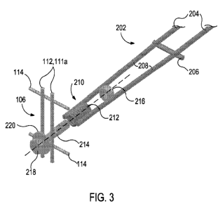
[0012] Figure 3 is an isometric view of a soil reinforcing element used in the
system
shown in Figure 1, according to one or more aspects of the present disclosure.
[0013] Figure 4 is a plan view of the system of constructing a mechanically
stabilized
earth structure, according to one or more aspects of the present disclosure.
2
CA 02798147 2012-10-31
WO 2011/159809 PCT/US2011/040543
[0014] Figure 5 is a side view of the connection apparatus for connecting at
least two
lifts or systems, according to one or more aspects of the present disclosure.
[0015] Figure 6A is an isometric view of another system of constructing a
mechanically
stabilized earth structure, according to one or more aspects of the present
disclosure.
[0016] Figure 6B is a side view of a soil reinforcing element used in the
system shown in
Figure 6A, according to one or more aspects of the present disclosure.
[0017] Figure 7 is an isometric view of an exemplary soil reinforcing element,
according
to one or more aspects of the present disclosure.
[0018] Figure 8 is an isometric view of another exemplary soil reinforcing
element,
according to one or more aspects of the present disclosure.
[0019] Figure 9 is an isometric view of another exemplary soil reinforcing
element,
according to one or more aspects of the present disclosure.
DETAILED DESCRIPTION
[0020] It is to be understood that the following disclosure describes several
exemplary
embodiments for implementing different features, structures, or functions of
the invention.
Exemplary embodiments of components, arrangements, and configurations are
described
below to simplify the present disclosure; however, these exemplary embodiments
are
provided merely as examples and are not intended to limit the scope of the
invention.
Additionally, the present disclosure may repeat reference numerals and/or
letters in the
various exemplary embodiments and across the Figures provided herein. This
repetition is
for the purpose of simplicity and clarity and does not in itself dictate a
relationship between
the various exemplary embodiments and/or configurations discussed in the
various Figures.
Moreover, the formation of a first feature over or on a second feature in the
description that
follows may include embodiments in which the first and second features are
formed in direct
contact, and may also include embodiments in which additional features may be
formed
interposing the first and second features, such that the first and second
features may not be
in direct contact. Finally, the exemplary embodiments presented below may be
combined in
any combination of ways, i.e., any element from one exemplary embodiment may
be used in
any other exemplary embodiment, without departing from the scope of the
disclosure.
[0021] Additionally, certain terms are used throughout the following
description and
claims to refer to particular components. As one skilled in the art will
appreciate, various
entities may refer to the same component by different names, and as such, the
naming
convention for the elements described herein is not intended to limit the
scope of the
invention, unless otherwise specifically defined herein. Further, the naming
convention used
herein is not intended to distinguish between components that differ in name
but not
3
CA 02798147 2012-10-31
WO 2011/159809 PCT/US2011/040543
function. Additionally, in the following discussion and in the claims, the
terms "including"
and "comprising" are used in an open-ended fashion, and thus should be
interpreted to
mean "including, but not limited to." All numerical values in this disclosure
may be exact or
approximate values unless otherwise specifically stated. Accordingly, various
embodiments
of the disclosure may deviate from the numbers, values, and ranges disclosed
herein
without departing from the intended scope. Furthermore, as it is used in the
claims or
specification, the term "or" is intended to encompass both exclusive and
inclusive cases,
i.e., "A or B" is intended to be synonymous with "at least one of A and B,"
unless otherwise
expressly specified herein.
[0022] Referring to Figure 1, illustrated is an isometric view of an exemplary
system 100
for erecting an MSE structure. In brief, and as will be described in more
detail below, the
system 100 may include one or more wire facings 102 stacked one atop the other
and
having one or more soil reinforcing elements 202 coupled thereto and extending
into fields
of backfill 103. One or more struts 118 may also be coupled to each wire
facing 102 for
structural reinforcement and adapted to maintain each wire facing 102 in a
predetermined
angular configuration. The backfill 103 may be sequentially added to the
system 100 in a
plurality of layers configured to cover the soil reinforcing elements 202,
thereby providing
tensile strength to the wire facings 102 and preventing the wire facings 102
from bulging
outward. A more detailed discussion of these and other elements of the system
100 follows
herewith.
[0023] Referring to Figures 2A and 2B, each wire facing 102 of the system 100
may be
fabricated from several lengths of cold-drawn wire welded and arranged into a
mesh panel.
The wire mesh panel can then be folded or otherwise shaped to form a
substantially L-
shaped assembly including a horizontal element 104 and a vertical facing 106
or wire facing.
In other embodiments, the horizontal element 104 and vertical facing 106
include
independent wire meshes that are coupled or otherwise attached at one end,
thereby
forming the substantially L-shaped assembly,
[0024] The horizontal element 104 may include a plurality of horizontal wires
108
welded or otherwise attached to one or more cross wires 110, such as an
initial wire 11 Oa, a
terminal wire 110b, and a median wire 110c. The initial wire 110a may be
disposed
adjacent and directly behind the vertical facing 106, thereby being positioned
inside the
MSE structure. The terminal wire 11Ob may be disposed at or near the distal
ends of the
horizontal wires 108. The median wire 11Oc may be welded or otherwise coupled
to the
horizontal wires 108 and disposed at a variety of lateral distances between
the initial and
terminal wires 110a,b. As can be appreciated, any number of cross wires 110
can be
4
CA 02798147 2012-10-31
WO 2011/159809 PCT/US2011/040543
employed without departing from the scope of the disclosure. For instance, in
at least one
embodiment, the median wire 110c may be excluded from the system 100.
[0025] The vertical facing 106 can include a plurality of vertical wires 112
extending
generally vertical with reference to the horizontal element 104 and laterally-
spaced from
each other. In one embodiment, the vertical wires 112 may be vertically-
extending
extensions of the horizontal wires 108. In other embodiments, the vertical
wires 112 may be
independent of the horizontal wires 108 where the vertical facing 106 is
independent of the
horizontal element 104. The vertical facing 106 may also include a plurality
of facing cross
wires 114, including a top-most cross wire 116, vertically-offset from each
other and welded
or otherwise attached to the vertical wires 112. The top-most cross wire 116
may be
vertically-offset a short distance above the last facing cross wire 114.
[0026] In at least one embodiment, each vertical wire 112 may be separated by
a
distance of about 4 inches on center from adjacent vertical wires 112, and the
facing cross
wires 114 may also be separated from each other by a distance of about 4
inches on center,
thereby generating a grid-like facing composed of a plurality of square voids
having about a
4" x 4" dimension. As can be appreciated, however, the spacing between
adjacent wires
112, 114 can be varied to more or less than 4 inches to suit varying
applications and the
spacing need not be equidistant. In one embodiment, the top-most cross wire
116 may be
vertically-offset from the last facing cross wire 114 by a distance X, as will
be discussed in
more detail below.
[0027] The wire facing 102 may further include a plurality of connector leads
111 a-g
extending from the horizontal element 104 and up the vertical facing 106. In
an
embodiment, each connector lead 111a-g may include a pair of horizontal wires
108 (or
vertical wires 112, if taken from the frame of reference of the vertical
facing 106) laterally-
offset from each other by a short distance. The short distance between
adjacent horizontal
or vertical wires 108, 112 to form the connector leads 111a-g can vary
depending on the
particular application, but may generally include about a one inch separation.
In one
embodiment, each connector lead 111 a-g may be equidistantly-spaced from
adjacent
connector leads 111a-g along the horizontal element 104 and/or vertical facing
106, and
configured to provide a visual indicator to an installer as to where a soil
reinforcing element
202 (Figures 1 and 3) may be properly attached to the facing 102. In at least
one
embodiment, each connector lead 111a-g may be spaced from each other by about
12
inches on center. Such relative distances, however, may vary to suit
particular applications.
[0028] Still referring to Figures 2A-2B, one or more struts 118 may be
operatively
coupled to the wire facing 102. As illustrated, the struts 118 may be coupled
to both the
CA 02798147 2012-10-31
WO 2011/159809 PCT/US2011/040543
vertical facing 106 and the horizontal element 104 at appropriate locations.
Each strut 118
may be prefabricated with or otherwise include a connection device 120
disposed at each
end of the strut 118. The connection device(s) may be configured to fasten or
otherwise
attach the struts 118 to both the horizontal element 104 and the vertical
facing 106. In at
least one embodiment, as can best be seen in Figure 5, the connection device
120 may
include a hook that is bent about 180 back upon itself. In other embodiments,
the
connection device 120 may include a wire loop that can be manipulated,
clipped, or
otherwise tied to both the horizontal element 104 and the vertical facing 106.
As can be
appreciated, however, the struts 118 can be coupled to the horizontal element
104 and the
vertical facing 106 by any practicable method or device known in the art
without departing
from the scope of the disclosure.
[0029] Each strut 118 may be coupled at one end to at least one facing cross
wire 114
and at the other end to the terminal wire 110b. In other embodiments, one or
more struts
118 may be coupled to the median wire 110c instead of the terminal wire 110b,
without
departing from the scope of the disclosure. As illustrated, each strut 118 may
be coupled to
the wire facing 102 in general alignment with a corresponding connector lead
111a-g. In
other embodiments, however, the struts 118 can be connected at any location
along the
respective axial lengths of any facing cross wire 114 and terminal wire 110b,
without
departing from the scope of the disclosure. In yet other embodiments, the
struts 118 may
be coupled to a vertical wire 112 of the vertical facing 106 and/or a
horizontal wire 108 of the
horizontal element 104, respectively.
[0030] The struts 118 are generally coupled to the wire facing 102 before any
backfill
103 (Figure 1) is added to the respective layer or "lift" of the system 100.
During the
placement of backfill 103, and during the life of the system 100, the struts
118 may serve as
structural reinforcement to prevent the vertical facing 106 from bending or
otherwise
extending past a predetermined vertical angle. For example, in the illustrated
embodiment,
the struts 118 may be configured to maintain the vertical facing 106 at or
near about 90
with respect to the horizontal element 104. As can be appreciated, however,
the struts 118
can be fabricated to varying lengths or otherwise attached at varying
locations along the
wire facing 102 to maintain the vertical facing 106 at a variety of angles of
orientation. The
struts 118 may allow installers to walk on the backfill 103 of the MSE
structure, tamp it, and
compact it fully before adding a new lift or layer.
[0031] Referring now to Figure 3, illustrated is an exemplary soil reinforcing
element 202
that may be attached or otherwise coupled to a portion of the wire facing 102
(Figures 2A
and 2B) in the construction of an MSE structure. The soil reinforcing element
202 may
6
CA 02798147 2012-10-31
WO 2011/159809 PCT/US2011/040543
include at least two longitudinal wires 204 that extend substantially parallel
to each other.
The longitudinal wires 204 may be joined to one or more transverse wires 206
in a generally
perpendicular fashion by welds at their intersections, thus forming a welded
wire gridworks.
[0032] In one or more embodiments, lead ends 208 of the longitudinal wires 204
may
generally converge and be welded or otherwise attached to a connector 210, or
end
connector. In at least one embodiment, the connector 210 (exploded in Figure 3
for ease of
viewing) may include a coil 212, a threaded rod 214, such as a bolt or a
length of rebar, and
a nut 216. As illustrated, the coil 212 may include a plurality of
indentations or grooves
defined along its axial length which provide a more suitable welding surface
for attaching the
lead ends 208 of the longitudinal wires 204 thereto. For example, where the
coil 212 is
resistance welded to the lead ends 208, such indentations and/or grooves can
result in a
stronger weld. In one embodiment, the coil 212 can be a helical or coil
spring. In other
embodiments, the coil 212 can be another nut or a coil rod that is welded to
the longitudinal
wires 204. Other exemplary embodiments of the connector 210 contemplated
herein are
described in co-owned U.S. Pat. No. 6,571,293 entitled "Anchor Grid Connector
Element,"
issued on February 11, 2003 and hereby incorporated by reference to the extent
not
inconsistent with the present disclosure.
[0033] To secure the soil reinforcing element 202 to a portion of the wire
facing 102
(Figure 2B), or more particularly the vertical facing 106, the head 218 of the
threaded rod
214 may be disposed on the front side of at least two vertical wires 112, such
as at a
connector lead 111a. The body of the threaded rod 214 can be extended through
the
vertical facing 106 and coil 212 and secured thereto with the nut 216 at its
end. As
illustrated, the head 218 may be prevented from passing through the vertical
wires 112 or
connector lead 111 a by employing a washer 220 disposed radially about the
threaded rod
and adapted to provide a biasing engagement with the vertical wires 112 or
connector lead
111a. As the nut 216 is tightened, it forces the coil 212 into engagement, or
at least
adjacent to, the back side of the vertical facing 106.
[0034] In embodiments where the lateral spacing of adjacent vertical wires 112
is such
that the connector 210 and a portion of the soil reinforcing element 202 may
be able to
extend through the vertical facing 106, it is further contemplated to employ a
secondary
washer or bearing plate (not shown) on the inside or back side of the vertical
facing 106.
For instance, at least one secondary washer or bearing plate may extend
radially around the
threaded rod and be disposed axially adjacent the coil 212 and large enough so
as to bear
on at least two vertical wires 112 and prevent the connector 210 and lead ends
208 from
passing through the vertical facing 106. Accordingly, the soil reinforcing
element 202 may
7
CA 02798147 2012-10-31
WO 2011/159809 PCT/US2011/040543
be secured against removal from the wire facing 102 on both the front and the
back sides of
the vertical facing 106.
[0035] Referring to Figure 4, depicted is a plan view of the system 100 where
at least
four soil reinforcing elements 202 are coupled to a wire facing 102. As
illustrated, the soil
reinforcing elements 202 may be attached to the wire facing 102 at one or more
connector
leads 111a-g. In one or more embodiments, soil reinforcing elements 202 may be
connected to every connector lead 111a-g, every other connector lead 111a-g,
every third
connector lead 111a-g, etc. For instance, Figure 4 depicts soil reinforcing
elements 202
connected to every other connector lead 111 a, 111 c, 111 e, and 111 g.
[0036] In one or more embodiments, the terminal wire 110b and/or median wire
110c
may be located at a predetermined distance from the initial wire 110a to allow
at least one
transverse wire 206 of the soil reinforcing element 202 to be positioned
substantially
adjacent the terminal and/or median wires 110b, 110c when the soil reinforcing
element 202
is secured against the wire facing 102 with the connector 210. Accordingly,
corresponding
transverse wires 206 may be coupled or otherwise attached to the terminal
and/or median
wires 110b, 110c. The transverse wires 206 may be positioned either directly
behind or in
front of the terminal and/or median wires 110b, 110c and secured thereto using
a coupling
device (not shown), such as a hog ring, wire tie, or the like. In yet other
embodiments, the
soil reinforcing element 202 is secured to only one or none of the terminal
and/or median
wires 110b, 110c.
[0037] In embodiments where the soil reinforcing element 202 is not coupled to
the
terminal or median wires 110b, 110c, it may be free to swivel in a horizontal
plane as
generally indicated by arrows A. As can be appreciated, this configuration
allows the soil
reinforcing elements 202 to swivel in order to avoid vertically-disposed
obstructions, such as
drainage pipes, catch basins, bridge piles, or bridge piers, which may be
encountered in the
backfill 103 (Figure 1) field.
[0038] As shown in both Figures 1 and 4, the system 100 may further include a
screen
402 disposed on the wire facing 102 once the soil reinforcing elements 202
have been
connected as generally described above. In one embodiment, the screen 402 can
cover all
or portions of both the vertical facing 106 and the horizontal element 104. As
illustrated, the
screen 402 may be placed on substantially all of the vertical facing 106 and
only a portion of
the horizontal element 104. In other embodiments, however, the screen 402 may
be
arranged on the wire facing 102 in different configurations, such as covering
the entire
horizontal element 104 or only a portion of the vertical facing 106. In
operation, the screen
402 may be configured to prevent backfill 103 (Figure 1) from leaking,
eroding, or otherwise
8
CA 02798147 2012-10-31
WO 2011/159809 PCT/US2011/040543
raveling out of the wire facing 102. In one embodiment, the screen 402 may be
a layer of
filter fabric. In other embodiments, however, the screen 402 may include
construction
hardware cloth or a fine wire mesh. In yet other embodiments, the screen 402
may include
a layer of cobble, such as large rocks that are too large to advance through
the square voids
defined in the vertical facing 106, but are small enough to generally prevent
backfill 103
materials from penetrating the wire facing 102.
[0039] Referring again to Figure 1, the system 100 can be characterized as a
lift 105
used in erecting an MSE structure wall to a predetermined height. To reach the
required
height, a plurality of lifts (e.g., lifts 105a and 105b) may be required. Each
lift 105a,b may
include the elements of the system 100 as generally described above in Figures
2A, 2B, 3,
and 4. While only two lifts 105a,b are shown in Figure 1, it will be
appreciated that any
number of lifts may be used to reach a desired height for the MSE structure.
As depicted,
the first lift 105a may be disposed generally below the second lift 105b and
the horizontal
elements 104 of each lift 105a,b may be oriented substantially parallel to and
vertically-
offset from each other. The angle of orientation for the vertical facings 106
of each lift
105a,b may be similar or may vary, depending on the application. For example,
the vertical
facings 106 of each lift 105a,b may be disposed at angles less than or greater
than 90 with
respect to horizontal.
[0040] In at least one embodiment, the vertical facings 106 of each lift
105a,b may be
substantially parallel and continuous, thereby constituting an unbroken
vertical ascent for
the facing of the MSE structure. In other embodiments, however, the vertical
facings 106 of
each lift 105a,b may be laterally offset from each other and form a stepped
facing. For
example, the disclosure contemplates embodiments where the vertical facing 106
of the
second lift 105b may be disposed behind or in front of the vertical facing 106
of the first lift
105a, and so on until the desired height of the MSE wall is realized.
[0041] In one or more embodiments, because of the added strength derived from
the
struts 118, each lift 105a,b may be entirely free from contact with any
adjacent lift 105a,b
(with exception of the backfill 103). Thus, in at least one embodiment, the
first lift 105a may
have backfill placed thereon up to or near the vertical height of the vertical
facing 106 and
compacted so that the second lift 105b may be placed completely on the
compacted backfill
103 of the first lift 105a therebelow. Whereas conventional systems would
require the
vertical facing 106 of the first lift 105a to be securely fastened to the
vertical facing 106 of
the second lift 105b to prevent its outward displacement, the present
disclosure allows each
lift 105a,b to be physically free from engagement with each other. This may
prove
advantageous during settling of the MSE structure. For instance, where
adjacent lifts
9
CA 02798147 2012-10-31
WO 2011/159809 PCT/US2011/040543
105a,b are not in contact with each other, the system 100 may settle without
causing
adverse binding which can potentially diminish the structural integrity of the
MSE structure.
[0042] Referring now to Figure 5, other embodiments of the disclosure include
engaging
the first and second lifts 105a,b in sliding engagement with one another using
the connector
210 of the soil reinforcing elements 202. As shown in Figure 5, each lift
105a,b may have a
corresponding vertical facing 106a, 106b. The first lift 105a may be disposed
substantially
below the second lift 105b, with its vertical facing 106a being placed
laterally in front of the
vertical facing 106b of the second lift 105b. Backfill 103 may be added to at
least a portion
of the first lift 105a to a first height or distance Y above the last facing
cross wire 114. The
second lift 105b may be disposed on top of the backfill 103, thereby also
being placed a
distance Y above the last facing cross wire 114. As will be appreciated, the
first height or
distance Y can be any distance or height less than the distance X. For
example, the
distance Y can be about but less than the distance X, thereby having the
backfill 103 level
up to but just below the top-most cross wire 116 of the vertical facing 106a.
[0043] In order to bring the vertical facings 106a,b of each lift 105a,b into
engagement
or at least adjacent one another, the threaded rod 214 of the connector 210
may be
configured to extend through each vertical facing 106a,b and be secured with
the nut 216.
In order to ensure a sliding engagement between the first and second lifts
105a,b, the nut
216 may be "finger-tightened," or tightened so as to nonetheless allow
vertical movement of
either the first or second lift 105a,b with respect to each other. Tightening
the nut 216 may
bring the coil 212 into engagement with the backside of the vertical facing
106b of the
second lift 105b, with the coil eventually resting on the initial wire 110a.
Tightening the nut
216 may also force the washer 220 into engagement with the vertical facing
106a of the first
lift 105a on the opposite side. Tightening the nut 216 may further bring the
top-most cross
wire 116 into engagement with the vertical facing 106b, thereby preventing the
outward
displacement of the vertical facing 106b. However, in other embodiments, the
top-most
cross wire 116 is not necessarily brought into contact with the vertical
facing 106b, but the
vertical facing 106b may be held in its angular configuration by the strut(s)
118 attached at
the upper facing cross wire 114 of the vertical facing 106b.
[0044] Placing the second lift 105b a distance Y above the upper facing cross
wire 114
allows the second lift 105b to vertically shift or translate the distance Y in
reaction to backfill
103 settling or thermal expansion/contraction of the MSE structure.
Accordingly, the
distance Y can be characterized as a distance that the second lift 105b may be
able to settle
without binding on the first lift 105a and thereby weakening the structural
integrity of the
MSE system.
CA 02798147 2012-10-31
WO 2011/159809 PCT/US2011/040543
[0045] Referring now to Figures 6A-6B, depicted is another exemplary
embodiment of
the system 100 depicted in Figure 1, embodied and described here as system
600. As
such, Figures 6A-6B may best be understood with reference to Figures 1-5,
wherein like
numerals correspond to like elements and therefore will not be described again
in detail.
Similar to the system 100 generally described above, system 600 may include
one or more
lifts 105a,b stacked one atop the other and having one or more soil
reinforcing elements 202
coupled to the wire facings 102. The soil reinforcing elements 202 extend into
the backfill
103 which is sequentially added to the system 600 in a plurality of layers
configured to cover
the soil reinforcing elements 202 and provide tensile strength to each wire
facing 102.
[0046] The soil reinforcing elements 202 in system 600, however, may include a
different type of connector 210 than that described in system 100, as
illustrated in Figure 3
above. For example, any type of threaded rod can be extended through the coil
212 and
secured thereto with a nut 216, thereby replacing the threaded rod 214 as
generally
described with reference to Figure 3. Referring to the exploded view of the
connector 210 in
Figure 6B, a threaded eye-bolt 602 with a head 604 may replace the threaded
rod 214. As
illustrated, the head 604 may be a loop having a centrally-defined aperture
605. To secure
the soil reinforcing element 202 to a portion of a wire facing 102, or in
particular the vertical
facing 106 thereof, the head 604 of the eye-bolt 602 may be disposed on the
front side of at
least two vertical wires 112, such as at a connector lead 111a, such that the
body of the
eye-bolt 602 can be extended through the coil 212 and secured thereto with the
nut 216 on
its opposite end. As illustrated, the loop or head 604 may be prevented from
passing
through the vertical wires 112 or connector lead 111 a by employing a washer
220 adapted
to provide a biasing engagement with the vertical wires 112 or connector lead
111 a on the
front side surface of the vertical facing 106. As the nut 216 is tightened, it
brings the coil
212 into engagement or at least adjacent to the back side of the vertical
facing 106, and the
washer 220 into engagement with the vertical wires 112 or connector lead 111 a
at the front
side.
[0047] In one or more embodiments, the body of the eye-bolt 602 may also be
threaded
through a second nut 606 adapted to be disposed against the washer 220 on the
outside of
the vertical facing 106. As illustrated, the body of the eye-bolt 602 can have
a non-threaded
portion 603 configured to offset the second nut 606 from the head 604 a
distance Z when
the second nut 606 is fully threaded onto the body. This may allow the head
604 to be
laterally-offset a short distance from the vertical facing 106, as shown in
Figure 6A.
[0048] As can be appreciated, having the head 604 offset from the vertical
facing 106
may provide an attachment means for a laterally offset facing, such as a
facing used in two-
11
CA 02798147 2012-10-31
WO 2011/159809 PCT/US2011/040543
stage MSE applications. Examples of two-stage MSE applications include co-
owned U.S.
Pat. App. No. 12/132,750, entitled "Two Stage Mechanically Stabilized Earth
Wall System,"
filed June 4, 2008, and U.S. Pat. App. No. 13/012,607, entitled "Two Stage
Mechanically
Stabilized Earth Wall System," filed January 24, 2011, the contents of each
application are
hereby incorporated by reference to the extent consistent with the present
disclosure. As
illustrated, the loop or head 604 may be horizontally-disposed, but may also
be vertically-
disposed without departing from the scope of the disclosure.
[0049] Referring now to Figure 7, illustrated is an exemplary soil reinforcing
element
700, according to one or more embodiments disclosed. The soil reinforcing
element 700,
and those disclosed in Figures 8 and 9 below, may be used in exemplary MSE
structures,
such as those described herein. Similar to the soil reinforcing element 202
described with
reference to Figure 3 above, the soil reinforcing element 700 may generally
include a
welded wire grid made of metal and having a pair of longitudinal wires 702
that are disposed
substantially parallel to each other and extend horizontally into the backfill
103 (Figures 1
and 6A). In some embodiments, there may be more than two longitudinal wires
702. The
longitudinal wires 702 are joined by a plurality of transverse wires 704
laterally-offset from
each other along the length of the longitudinal wires 702. In one embodiment,
the
transverse wires 704 may be arranged generally perpendicular to the
longitudinal wires 702,
but other angles of relative configuration are also contemplated herein
without departing
from the scope of the disclosure.
[0050] The transverse wires 704 may be coupled to the longitudinal wires 702
by welds
or other suitable attachment means at their intersections, such as with rebar
ties. The
spacing between each longitudinal wire 702 may be about 2 inches, while the
spacing
between each transverse wire 704 may be about 6 inches. As can be appreciated,
however, the spacing and configuration of adjacent respective wires 702, 704
may vary for a
variety of reasons, such as the combination of tensile force requirements that
the soil
reinforcing element 700 must endure and resist.
[0051] Each longitudinal wire 702 may have a lead end 706 that generally
converges
toward an adjacent lead end 706. Although a specific angle of convergence Q of
the lead
ends 706 is shown in Figure 7, it will be appreciated that any angle of
convergence Q of the
lead ends 706 may be employed without departing from the scope of the
disclosure. In one
embodiment, the lead ends 706 converge and terminate at a wall end 708 or a
connection
end of the element 700. The wall end 708 may be configured to receive or
otherwise be
attached to an end connector 710 adapted to attach the soil reinforcing
element 700 to a
variety of types of vertical facings (not shown), such as a wire facing, a
concrete facing, or a
12
CA 02798147 2012-10-31
WO 2011/159809 PCT/US2011/040543
sheet metal facing. Once appropriately secured to the vertical facing and
compacted within
the backfill 103 (Figures 1 and 6A), the soil reinforcing element 700 provides
tensile strength
to the vertical facing and prevents any outward movement and shifting thereof.
[0052] The end connector 710 is illustrated as a dashed box since there are
numerous
end connectors 710 that may be used in conjunction with the soil reinforcing
element 700,
without departing from the scope of the disclosure.
[0053] The soil reinforcing element 700 may be made of lengths of wire or bar
stock that
define numerous deformations 712 on the surface thereof. In one embodiment,
the
deformations 712 are positively defined and extend radially-outward from the
surface of
each wire 702, 704. The positive deformations 712 may be formed by cold-
forming
processing, which increases the strength of the wires 702, 704 via strain
hardening.
Consequently, the positive deformations 712 provide higher tensile capacity
yield strength.
For example, the tensile capacity of a soil reinforcing element having smooth
wires 702, 704
is about 65 ksi, while positively deformed wires 702, 704 provide a tensile
capacity that is
about 20% greater, or about 80 ksi.
[0054] In other embodiments, the deformations 712 are negatively defined and
extend
radially-inward from the surface of each wire 702, 704. Wires 702, 704 having
negative
deformations 712 may include lengths of rebar or similar types of bar stock.
Whether
positively or negatively defined, however, the deformations 712 also serve to
increase the
pull-out capacity of the soil reinforcing element 700, whereby it becomes more
difficult to pull
the soil reinforcing element 700 through compacted soil in the backfill 103
(Figures 1 and
6A).
[0055] Referring now to Figure 8, illustrated is another soil reinforcing
element 800,
according to one or more embodiments of the disclosure. The soil reinforcing
element 800
may be similar in some respects to the soil reinforcing element 700 of Figure
7. Accordingly,
the soil reinforcing element 800 may be best understood with reference to
Figure 7, where
like numerals designate like elements that will not be described again in
detail. Unlike the
soil reinforcing element 700 of Figure 7, the soil reinforcing element 800 has
a connection
end where the lead ends 706 generally converge but are not coupled to each
other.
Instead, the lead ends 706 provide an area where an end connector 710 may be
coupled
thereto.
[0056] The deformations 712 defined in the surface of the lead ends 706
provide a more
effective resistance weld to the end connector 710. For example, the
deformations 712
allow the metal in the soil reinforcing element 800 to puddle quicker, thereby
requiring less
heat and less pressure to generate a solid resistance weld to the end
connector 710.
13
CA 02798147 2012-10-31
WO 2011/159809 PCT/US2011/040543
Moreover, having deformations 712 defined on the lead ends 706 may eliminate
the need to
have grooves or indentations on the end connector 710, such as the grooves and
indentations shown on the coil 212 in Figures 3 and 6B. Accordingly, one of
the end
connectors 710 that could be attached to the soil reinforcing element 800 is
the connector
210 shown and described in Figures 3 and 6B.
[0057] It will be appreciated that several other types of end connectors 710
may also be
coupled to the lead ends 706 of the soil reinforcing element 800. For example,
the
connection stud disclosed in co-owned U.S. Pat. App. No. 12/479,488 entitled
"Mechanically
Stabilized Earth Connection Apparatus," filed June 5, 2009 and incorporated
herein by
reference to the extent not inconsistent with the present disclosure, may be a
suitable end
connector 710. The connection stud may include a cylindrical body bent to
about a 90
angle relative to horizontal, thus forming a vertical portion. The vertical
portion may
terminate at a head that is noticeably larger than the diameter or cross-
section of the vertical
portion. The tail end of the body may include indentations or thread markings
capable of
enhancing the resistance weld to the lead ends 706.
[0058] The connection studs disclosed in co-owned U.S. Pat. App. No.
12/756,898
entitled "Retaining Wall Soil Reinforcing Connector and Method," filed April
8, 2010 and
incorporated herein by reference to the extent not inconsistent with the
present disclosure,
may also be a suitable end connector 710. One disclosed connection stud is
created from a
one-piece forging process and has a tab that extends from its stem. The stem
may be
either convex or concave longitudinally and include a plurality of
indentations, grooves, or
threads defined along its axial length, either cast or otherwise machined into
the stem.
Another disclosed connection stud is a loop-type connection stud where the tab
is generally
replaced with a loop or ring. The stem can define axial channels disposed
along opposing
sides of its axial length, and having a plurality of grooves cast in or
otherwise machined
therein. Yet another disclosed connection stud is a dual-prong connection
stud, where the
tab is replaced with a pair of prongs vertically offset from each other and
extending axially
from the stem. Each prong may define a centrally-disposed perforation,
coaxially aligned
with each other, and used for connecting the dual-prong connection stud to a
facing anchor,
for example.
[0059] The connection stud disclosed in co-owned U.S. Pat. App. No. 12/818,011
entitled "Mechanically Stabilized Earth System and Method," filed June 17,
2010 and
incorporated herein by reference to the extent not inconsistent with the
present disclosure,
may also be a suitable end connector 710. The connection stud may include a
stem and a
connector, where the stem includes a plurality of indentations or grooves
defined along its
14
CA 02798147 2012-10-31
WO 2011/159809 PCT/US2011/040543
axial length and the connector may be hook-shaped or otherwise turned about
180 from the
axial direction of the stem.
[0060] Referring now to Figure 9, illustrated is another soil reinforcing
element 900,
according to one or more embodiments of the disclosure. The soil reinforcing
element 900
may also be similar in some respects to the soil reinforcing element 700 of
Figure 7.
Accordingly, the soil reinforcing element 900 may be best understood with
reference to
Figure 7, where like numerals designate like components that will not be
described again in
detail. Unlike the soil reinforcing elements 700, 800 described above, the
soil reinforcing
element 900 does not have lead ends 706 that converge, but instead the
longitudinal wires
704 remain generally parallel to each other along their entire length.
Accordingly, the end
connector 710 that attaches the soil reinforcing element 900 to a vertical
facing is
necessarily of a different configuration.
[0061] For example, the facing anchor assembly disclosed in co-owned U.S. Pat.
App.
No. 12/684,479 entitled "Wave Anchor Soil Reinforcing Connector and Method,"
filed
January 8, 2010 and incorporated herein by reference to the extent not
inconsistent with the
present disclosure, may be a suitable end connector 710. The facing anchor
assembly may
include a pair of plates that are horizontally-disposed from each other and
have a vertically-
disposed tab at one end and define a trough at the other end. Interposed
between the tab
and the trough of each plate may be at least two longitudinally-offset
transverse protrusions
for capturing and seating at least two transverse wires 704. Another facing
anchor
assembly includes a one-piece device capable of receiving and securely seating
at least
one transverse wire 704, and simultaneously connecting to at least one
horizontal wire of a
vertical wire facing. The facing anchor may include a first side and a second
side connected
by a connecting member at one end, wherein the connecting member may includes
a 180
turn in the facing anchor to define a gap between the first and second sides.
[0062] In other embodiments, the soil reinforcing element 900 may have
upwardly
extending extensions (not shown) disposed at its lead end. Such embodiments
are
described in co-owned U.S. Pat. App. No. 12/861,632 entitled "Soil Reinforcing
Connector
and Method of Constructing a Mechanically Stabilized Earth Structure," filed
August 23,
2010 and incorporated herein by reference to the extent not inconsistent with
the present
disclosure. As described in the incorporated application, the upwardly
extending extensions
of the soil reinforcing element 900 may be coupled to a vertical wire facing
using a
connection device. The connection device includes a bearing plate having one
or more
longitudinal protrusions configured to seat the upwardly-extending extensions
of the soil
reinforcing element 900. The bearing plate may be configured to receive a
threaded rod via
CA 02798147 2012-10-31
WO 2011/159809 PCT/US2011/040543
a centrally-defined perforation. The rod may be extensible through the
perforation and
further through any adjacent vertical facings, and secured from removal by
threading a nut
onto its end.
[0063] In yet other embodiments, the end connector 710 may include a splice
such as
that disclosed in co-owned U.S. Pat. App. No. 12/887,907 entitled "Splice for
a Soil
Reinforcing Element or Connector," filed September 22, 2010 and incorporated
herein by
reference to the extent not inconsistent with the present disclosure. The
splice may be used
to lengthen the soil reinforcing element by coupling it to another soil
reinforcing element or
grid strip. The splice includes one or more wave plates, each wave plate
including one or
more transverse protrusions longitudinally-offset from each other and
configured to receive
one or more transverse wires 704 therein. Co-axially defined apertures in each
wave plate
are used to secure the wave plates together.
[0064] It will be appreciated by those skilled in the art that several
different types of end
connectors 710 (not specifically disclosed herein) may be used with the soil
reinforcing
elements 700, 800, 900 described herein, without departing from the scope of
the
disclosure.
[0065] The foregoing has outlined features of several embodiments so that
those skilled
in the art may better understand the present disclosure. Those skilled in the
art should
appreciate that they may readily use the present disclosure as a basis for
designing or
modifying other processes and structures for carrying out the same purposes
and/or
achieving the same advantages of the embodiments introduced herein. Those
skilled in the
art should also realize that such equivalent constructions do not depart from
the spirit and
scope of the present disclosure, and that they may make various changes,
substitutions and
alterations herein without departing from the spirit and scope of the present
disclosure.
16