Note: Descriptions are shown in the official language in which they were submitted.
CA 02798165 2012-11-01
WO 2011/159631 PCT/US2011/040229
ELECTRODE ARRAY HAVING EMBEDDED ELECTRODES
AND METHODS OF MAKING THE SAME
c
CROSS-REFERENCE TO RELATED APPLICATIONS
This application clai-ns the benefit under ofU.S. Provisional Patent
Application Serial
No. 611"356,529 filed on June 18, 2010, which :is incorporated herein by
reference.
FIELD
The invention is directed to devices and methods for brain stimulation
including deep
brain stir: elation. in addition, 'he invention is directed to devices and
method for brain
stimulation using a lead having embedded segmented electrodes
BACKGROUND
Deep brain stimulation can be useful for treating a variety of conditions
including, for
example, Parkinson's disease, dystonia, essential tremor, chronic pain, t-
luntington's Disease,
levodopa induced dyskinesias and rigidity, bradykinesia, epilepsy and
seizures, eating
disorders, and mood disorders. Typically, a lead with a stimulating electrode
at or near a tip
of the lead provides the stimulation to target neurons in the brain. Magnetic
resonance
imaging (MR1) or computerized tomography (CT) scans can provide a starting
point for
determining where the stimulating electrode should be positioned to provide
the desired
stimulus to the target neurons.
Upon insertion, current is introduced along the length of the lead to
stimulate target
neurons in the brain. This stimulation is provided by electrodes, typically in
he form of
rings, disposed on the lead. The current projects from each electrode
similarly and in all
directions at any given length along the axis of the lead. Because of the
shape of the
electrodes, radial selectivity of the current is minimal. This results in the
unwanted
stimulation of neighboring neural tissue, undesired side effects and an
increased duration of
time for the proper therapeutic effect to be obtained.
I
CA 02798165 2012-11-01
WO 2011/159631 PCT/US2011/040229
BRIEF SUMMARY
One embodiment is a. method of manufacturing a device for brain stimulation.
The
method includes forming a lead body having a distal end section and coupling
at least one
pre-electrode to the distal end section of the lead body. The pre-electrode
defines a divider
with a plurality of partitioning arms, and has a plurality of fixing lui ens.
A portion of the
pre-electrode aligned with the portioning arms is removed to divide the pre-
electrode into a
plurality of segmented electrodes. Each of the plurality of segmented
electrodes defines at
least one of the plurality of fixing lumens at least partially disposed
throw=11 the segmented
electrode.: material is introduced through the at least one fixing lumen to
couple the
plurality of segmented electrodes to the lead body.
Another embodiment is a device for brain stimulation that includes an
insulative
tubing having a distal end section and at least one electrode frame disposed
on the distal end
section of the insulative tubing. The at least one electrode ranee is formed
of an insulative
material. Each of the at least one electrode frame defines at least one
electrode cavity. The
device also includes a plurality of segmented electrodes with at least one of
the plurality of
segmented electrodes disposed within. each of the at least one electrode
cavity.
Yet another embodiment is a method of manufacturing a device for brain
stimulation.
The method includes forming an insulative carrier having a plurality
ofapertures for
receiving a plurality of segmented electrodes and coupling a plurality of
segmented
electrodes to the insulative carrier. One of the plurality of segmented
electrodes is disposed
within each of the plurality of apertures and each of the plurality of
segmented electrodes has
at least one flange for securing the segmented electrode within the insulative
carrier. The
method also includes wrapping the insulative carrier around a mandrel to form
a cylindrical
lead body,
A further e, ibodiment is a method of manufacturing a device for brain
stimulation.
The method includes forming an insulative tubing having a distal end section
and forming at
least one conductor lumen through the insulative tubing. The at least one
conductor lumen
extends longitudinally through the insulative tubi ig. The method further
includes
introducing a plurality of electrode tribes through the at least one conductor
lumen of the
insulative tubing, and removing a portion of the outer surface of the
insulative- tubing to
expose a portion of a. one of the at least one electrode tube
2
CA 02798165 2012-11-01
WO 2011/159631 PCT/US2011/040229
BRIEF DESCRIPTION OF THE DRAWINGS
ikon-limiting and non-exhaustive embodiments of the present invention are
described
with reference to the following drawings. In the dratiwwings, Tice reference
numerals refer to
like parts throughout the various figures t.inless otherwise specified.
For a better understanding of the present invention, reference will be made to
the
following Detailed Description, which is to be read in association with the
accompanying
drawings, wherein:
FIG. I A is a schematic perspective view of one embodiment of a portion of a
lead
having a plurality of segmented electrodes and a ring electrode, according to
the invention;
1.0 FIG. I ft is a schematic perspective view of another embodiment of a lead
having a
plurality of segmented electrodes arranged in staggered orientation and a ring
electrode,
according to the invention;
FIG. 2 is a schematic diagram of radial c anent steering along various
electrode levels
along the length of a lead, according to the invention;
FIG. 3A is a schematic perspective view of one embodiment of a pre-electrode,
according to the invention;
FIG. 3B is a schematic perspective view of a second embodiment of a pre-
electrode,
according to the invention;
FIG. 4 is a schematic perspective view of one embodiment of a segmented
electrode,
according to the invention;
FIG. 5A is a schematic perspective view of one embodiment of a pre-electrode
disk
coupled to conductors, according to the invention;
FIG. 5I3 is a schematic perspective view of the pre-electrode disk of FIG. SA
after
centerless grinding, according to the invention;
FIG. 6A is a. schematic perspective view of one embodiment of an electrode
frame,
according to the invention;
3
CA 02798165 2012-11-01
WO 2011/159631 PCT/US2011/040229
FIG. 6B is a schematic perspective view of a second embodiment of an electrode
frame, according to the invention;
FIG. 6C is a schematic perspective view of a third embodiment of art electrode
fame,
according to the invention;
FIG. 7A is a schematic perspective view of one embodiment of a segmented
electrode
corresponding to the electrode frame of FIG. 6A, according to the invention;
FIG. 713 is a schematic perspective view of a second embodiment of a segmented
electrode corresponding to the electrode frame of FIG. 6B, according to the
invention;
FIG, 7C is a schematic perspective view of a third embodiment of a segmented
electrode corresponding to the electrode frame of FIG, 6C, according to the
invention;
FIG. 8 is a schematic perspective view of the segmented electrodes of FIG. 7A
being
press fit into the electrode fame of FIG. 6A according to the invention;
FIG. 9A is a. schematic perspective view of one embodiment of a. multi-lumen
tubing,
according to the invention;
FIG. 9B is a schematic perspective view of the multi-lumen tubing of FIG. 9A
after
ablating portions of the tubing, according to the invention;
FIG. I OA is a schematic perspective view of one embodiment of a lead
consisting of a
multi-lumen tubing and electrode frames having a plurality of segmented
electrodes,
according to the invention;
FIG. I OB is a. schematic perspective view of the lead of FIG. I OA after
removing
portions of the electrode frame, according to the invention;
FIG, I IA is a schematic perspective view of one embodiment of an electrode
having
flanges, according to the invention;
FIG, 1113 is a schematic perspective view of one embodiment of the electrodes
of
?5 FIG. 1 I A disposed in a carrier, according to the invention;
4
CA 02798165 2012-11-01
WO 2011/159631 PCT/US2011/040229
FI.G. I I C is a schematic side view of one embodiment of the carrier of FIG.
11B after
being wrapped to form a lead, according to the invention;
FIG. 12A is a schematic perspective view of one embodiment of a lead body
having
electrode tubes, according to the invention;
FIG. 12B is a schematic perspective view of one embodiment of an electrode
tube
having a groove, according to the invention; and
FIG. 13 is a schematic side view of one embodiment of a device for brain
stimulation,
according to the invention.
DETAILED DESCRIPTION
The present invention is directed to the area of devices and methods for b
rain
stimulation including deep brain stimulation. In addition, the invention is
directed to devices
and method for brain stimulation ?using a lead having a plurality of
concentric windowed
cylinders.
A lead for deep brain stimulation may include stimulation electrodes,
recording
electrodes, or a combination of both. A practitioner may determine the
position of the target
neurons using the recording electrode(s) and then position the stimulation
electrode(s)
accordingly without removal of a recording lead and insertion of a stimulation
lead. In some
embodiments, the same electrodes can be used for both recording and
stimulation. In some
embodiments, separate leads can be used; one with recording electrodes which
identify target
neurons, and a second lead with stimulation electrodes that replaces the first
after target
neuron identification. A lead may include recording electrodes spaced around
the
circumference of the lead to more precisely determine the position of the
target neurons. In
at least some erribodiments, the lead is rotatable so that the stimulation
electrodes can be
aligned with the target neurons after the neurons have been located using the
recording
electrodes.
Deep brain stimulation devices and leads are described in the art. See, for
instance,
US. Patent Publication 2006/0149335 Al ("Devices and Methods For Brain
Stimulation"),
and co-pending patent application U.S. Ser. No. 12/237,888 ("Leads With Non-
Circular-
5
CA 02798165 2012-11-01
WO 2011/159631 PCT/US2011/040229
Shaped Distal Ends For Brain Stimulation Systems and Methods of Making and
Using"). Each
of these references is incorporated herein by reference in its respective
entirety.
FIG. 13 illustrates one embodiment ofa device 1300 for brain stimulation. The
device
includes a lead 1310, segmented electrodes 1320, a connector 1340 for
connection ofthe
electrodes to a control unit, and a stylet 1360 for assisting in insertion and
positioning of the
lead in the patient's brain. The stylet 1360 can be made of a rigid material.
Examples of
suitable materials include tungsten, stain less steel, or plastic. The stylet
1.360 may have a
handle 1370 to assist insertion into the lead, as well as rotation of the
stylet and lead, The
connector 1340 fits over the proximal end of the lead 1310, preferably after
removal of the
stylet 1360.
In one example of operation, access to the desired position in the brain can
be
accomplished by drilling a hole in the patient's skull or cranium with a
cranial drill
(comt-nonly referred to as a burr), and coagulating and incising the dura
mater, or brain
covering. The 'lead 1310 can be inserted into the cranium and brain tissue
with the assistance
of the stylet 1360. The lead can be guided to the target location within the
brain using, for
exan:iple, a stereotactic frame and a rnicrodrive motor system. In some
enmibodiments, the
nricrodrive motor system can be fully or partially automatic. The rnierodrive
motor system
may be configured to perform one or more the following actions (alone or in
combination);
insert the lead, retract the lead, or rotate the lead. In some embodiments,
measurement
devices coupled to the muscles or other tissues stimulated by the target
neurons or a unit
responsive to the patient or clinician can be coup led to the control unit or
microdrive motor
system. The measurement device, user, or clinician can indicate a response by
the target
muscles or other tissues to the stimulation or recording electrode(s) to
further identify the
target neurons and facilitate -Positioning of the stimulation electrode(s).
For example, if the
target neurons are directed to a muscle experiencing tremors, a measurement
device can be
used to observe the muscle and indicate changes in tremor frequency or
amplitude in
response to stimulation of neurons. Alternatively, the patient or clinician
may observe the
muscle and provide feedback.
It will be understood that the lead 1310 for deep brain stimulation can
include
stimulation electrodes, recording electrodes, or both. In at least some
embodiments, the lead
6
CA 02798165 2012-11-01
WO 2011/159631 PCT/US2011/040229
is rotatable so that the stimulation electrodes can be aligned with the target
neurons after the
neurons have been located using the recording electrodes.
Stimulation electrodes may be disposed on the circumference of the lead to
stimulate
the target neurons. Stimulation electrodes may be ring-shaped so that current
projects from
each electrode equally in every direction at any given length along the axis
of the lead. To
achieve current steering, segmented electrodes can be utilized additionally or
alternatively.
Though the following description discusses stimulation electrodes, it will be
understood that
all configurations of the stimulation electrodes discussed may be utilized in
arranging
recording electrodes as well.
in the field of deep brain stimulation, radially segmented electrode arrays
(RSEA)
have been developed to provide superior radial selectivity of current.
Radially segmented
electrode arrays are useful for deep brain stimulation because the target
structures in the deep
brain are often not symmetric about the axis of the distal electrode array. In
some cases, a
target may be located on one side of a plane running through the axis of the
lead. In other
cases, a target may be located at a plane that is offset at some angle from
the axis of the lead.
Thus, radially segmented electrode arrays may be useful for selectively
simulating tissue.
Figure ; A illustrates one embodiment of a lead 100 for brain stimulation. The
device
includes a lead body 1. 10, one or more ring, electrodes 120, and a plurality
of segmented
electrodes 130. The lead body 1 1.0 can be for med of a biocompatible, non-
conducting
material such as, for example, a polymeric material. Suitable polymeric
materials include,
but are not limited to, silicone, polyurethanes, polyether polyurethane,
polycarbonate
polyurethane, or silicone-polyurethane copolymer. In at least some instances,
the lead may
be in contact with body tissue for extended periods of titre. In at least some
embodiments,
the lead has a cross-sectional diameter of no more than 1.5 rim and may be in
the range of
0.75 to 1.5 rpm. In at least some embodiments, the lead has a length of at
least 10 cm and the
length of the lead may be in the range of 25 to 70 cm.
Stimulation electrodes may be disposed on the lead body 11 J. These
stimulation
electrodes may be made using a ,petal, alloy, conductive oxide, or any other
suitable
conductive material. Examples of suitable materials include, but are not
limited to, platinum,
iridium, platinum iridium alloy, stainless steel, titanium, or tungsten.
Preferably, the
7
CA 02798165 2012-11-01
WO 2011/159631 PCT/US2011/040229
stimulation electrodes are made of a material that is biocompatible and does
not substantially
corrode under expected operating conditions in the operating environment for
the expected
duration of use.
In at least some embodiments, any of the electrodes can be used as an anode or
cathode and carry anodic or cathodic current, in some instances, an electrode
might be an
anode for a period of time and a cathode for a period of time. In other
embodiments, the
identity of a particular electrode or electrodes as an anode or cathode might
be fixed.
The lead contains a plurality of segrrmented electrodes 130. Any number of
segmented
electrodes 130 may be disposed on the lead body 110. In some embod:inerts, the
segmented
electrodes 130 are grouped in sets of segmented electrodes, each set disposed
around the
circumference of the lead at or near a particular longitudinal position. The
lead may have any,
number of sets of segmented electrodes. In at least some embodiments, the lead
has one, two,
three, four, five, six, seven, or eight sets of segmented electrodes. In at
least some
e nbodiments, each set of segmented electrodes contains the same number of
segmented
electrodes 30. In some embodiments, each set of segmented electrodes contains
three
segmented electrodes 130. In at least some other embodiments, each set of
segmented
electrodes contains two, four, five, six, seven or eight segmented electrodes.
The segmented,
electrodes 130 may vary in size and shape. For example, in FIG. I B, the
segmented
electrodes 130 are shown as portions of a ring or curved rectangular portions.
In some other
%0 embodiments, the segmented electrodes 130 are curved square portions. The
shape of the
segmented electrodes 130 may also be substantially triangular, diamond-shaped,
oval,
circular or spherical. In some embodiments, the segmented electrodes 130 are
all of the same
size, shape, diameter, width or area or any combination thereof. In some
enibodimen Its, the
segmented electrodes of each set (or even all segmented electrodes) may be
identical in size
and shape.
in at least some embodiments, each set of segmented electrodes 130 may be
disposed
around the circumference of the lead body 110 to form a substantially or
approximately
cylindrical shape around the lead body I10. The spacing of the segmented
electrodes 130
around the circumference of the lead body 1 10 may vary. In at least some
embodiments,
equal spaces, gaps or cutouts are disposed between each segmented electrodes
130 around the
circumference of the lead body 110. In other embodiments, the spaces, gaps or
cutouts
8
CA 02798165 2012-11-01
WO 2011/159631 PCT/US2011/040229
between segmented electrodes may differ in size or shape. in other
embodiments, the spaces,
gaps. or cutouts between segmented electrodes may be uniform for a particular
set of
segmented electrodes or for all sets of segmented electrodes. The segmented
electrodes 13 0
may be positioned in irregular or regular intervals around the lead body 110.
Stimulation electrodes in the form of ring electrodes 120 may be disposed on
any part
of the. lead body 110, usually near a distal end of the lead. FIG. 1A
illustrates a portion of a
lead having one ring electrode. Any number of ring electrodes may be disposed
along the
length of the lead body 110. For example, the lead body n may have one ring
electrode, two
ring electrodes, three ring electrodes or four ring electrodes. In some
embodiments, the lead
will have five, six, seven or eight ring electrodes. Other embodiments do not
include ring
electrodes.
in some ernbodirnents, the ring electrodes 120 are substantially cylindrical
and wrap
around the entire circumference of the lead body I 10, In some embodiments,
the outer
diameter of the ring electrodes 120 is substantially equal to the outer
diameter ofthe lead
body 110. Furthermore, the width of -ring electrodes 120 may vary according to
the desired
treatment and the location of the target neurons. In some embodiments the
width of the ring
electrode 120 is less than or equal to the diameter of the ring electrode 120.
In other
embodiments, the width of the ring electrode 120 is greater than the diameter
of the ring
electrode 120.
Conductors (not shown) that attach to or from the ring electrodes 120 and
segmented
electrodes 130 also pass through the lead body 1 10. These conductors may pass
through the
material of the lead or through a lumen defined by the lead. The conductors
are presented at
a connector or coupling of the electrodes to a control unit (not shown). In
one embodiment,
the stimulation electrodes correspond to wire conductors that extend out of
the lead body 110
and are then trimmed or ground down flush with the lead surface. The
conductors may be
coupled to a control unit to provide stimulation signals, often in the form of
pulses, to the
stimulation electrodes.
FIG. I B is a schematic perspective view of another embodiment of a lead
having a
plurality of segmented electrodes, As seer in FIG. 1 B, the plurality of
segmented electrodes
130 may be arranged in different orientations relative to each other. In
contrast to FIG. I A,
9
CA 02798165 2012-11-01
WO 2011/159631 PCT/US2011/040229
where the three sets of segmented electrodes are aligned along the length of
the lead body
110, FIG. I B displays another embodiment in which the three sets of segmented
electrodes
130 are staggered. In at least some embodiments, the sets of segmented
electrodes are
staggered such that no segmented electrodes are aligned along the length of
the lead body
110. In some embodiments, the segmented electrodes may be staggered so that at
least one of
the segmented electrodes is aligned with another segmented electrode of a
different set, and
the other segmented electrodes are not aligned,
Any number of segmented electrodes 130 may be disposed on the lead body 110 in
any number of sets. FIGS. I A and I B illustrate embodiments including three
sets of
segmented electrodes. These three sets of segmented electrodes 130 may be
disposed in
different configurations. For example, three sets of segmented electrodes 130
may be
disposed on the distal end of the lead body 110, distal to a ring electrode
120. Alternatively,
three sets of segn ented electrodes 130 may be disposed proximal to a ring
electrode 120. By
varying the location of the segmented electrodes 130, different coverage of
the target neurons
may be selected. For example, a specific configuration may be useful if the
physician
anticipates that the neural target will be closer to the distal tip of the
lead body 110, while
another arrangement may be useful if the physician anticipates that the neural
target will be
closer to the proximal end of the lead body- 110. In at least some
embodiments, the ring
electrodes 120 alternate with sets of segmented electrodes 130.
Any combination of ring electrodes 120 and segmented electrodes 1311 may be
disposed on the lead, In some embodiments the segmented electrodes are
arranged in sets.
For example, a lead may include a first ring electrode 120. two sets of
segmented electrodes,
each set formed of three segmented electrodes 1.30, and a final ring electrode
120 at the end
of the lead. This configuration may simply be referred to as a 1-3-3-1
configuration. 1*1 may
be useful to refer to the electrodes with this shorthand notation. Other eight
electrode
configurations include,, for example, a 2-2-2-2 configuration, where four sets
of segmented
electrodes are disposed on the lead, and a 4-4 configuration, where two sets
of segmented
electrodes, each having four segmented electrodes 130 are disposed on the
lead. In some
embodiments, the lead will have 16 electrodes, Possible configurations for a
16-electrode
lead include, but are not limited to 4-4-4-4, 8-8, 3-3-3-3-3-1 (and all
rearrangements of this
configuration), and
CA 02798165 2012-11-01
WO 2011/159631 PCT/US2011/040229
FIG. 2 is a schematic diagram to illustrate radial current steering along
various
electrode. levels along the length of a lead. While conventional lead
configurations with ring
electrodes are only able to steer current along the length of the lead (the z-
axis), the
segmented electrode configuration is capable of steering current in the x-
axis, y-axis as well
as the z-axis. Thus, the ce.ntroid of stimulation may be steered in any
direction in the three-
dimensional space surrounding the lead body 110. In some embodiments, the
radial distance,
r, and the angle 0 around the circumference of the lead body 11 0 may be
dictated by the
percentage of anodic current (recognizing that stimulation predominantly
occurs near the
cathode, although strong anodes may cause stimulation as well) introduced to
each electrode
as will he described in greater detail below, In at least some embodiments,
the configuration
of anodes and cathodes along the segmented electrodes 130 allows the centroid
of stimulation
to be shifted to a variety of different locations along the lead body t 10.
As can be appreciated from FIG. 2, the centroid of stimulation can be shifted
at each
level along the length of the lead. The use of multiple sets of segmented
electrodes 130 at
different levels along the length of the lead allows for three-dimensional
current steering, In
some embodiments, the sets of segmented electrodes 130 are shifted
collectively (i.e. the
centroid of simulation is similar at each level along the length of the lead).
In at least some
other embodiments, each set of segmented electrodes 130 is controlled
independentl; . Each
set of segmented electrodes may contain two, three, four, gave, six, seven,
eight or more
segmented electrodes. It will be understood. that different stimulation
profiles may be
produced by varying the number of segmented electrodes at each level. For
example, when
each set of segmented electrodes includes only two segmented electrodes,
uniformly
distributed gaps (inability to stimulate selectively) may be formed in the
stimulations profile.
in some embodiments, at least three segmented electrodes 130 are utilized to
allow for true
360' selectivity.
In addition to 360" selectivity, a lead having segmented electrodes may
provide
several advantages. First, the lead may provide for more directed stimulation,
as well as less
``wasted" stimulation (i.e. stimulation of regions other than the target
region). By directing
stimulation toward the target tissue, side effects may be reduced.
Furthermore, because
stimulation is directed toward the target site, the battery in an implantable
pulse generator
may last for a longer period of time between recharging.
7l
CA 02798165 2012-11-01
WO 2011/159631 PCT/US2011/040229
As previously indicated, the foregoing configurations may also be used while
utilizing
recording electrodes. In some embodiments, measurement devices coupled to the
muscles or
other tissues stimulated by the target neurons or a unit responsive to the
patient or clinician
can be coupled to the control unit or microdrive motor system. The measurement
device,
user, or clinician can indicate a response by the target muscles or other
tissues to the
stimulation or recording electrodes to further identify the target neurons and
facilitate
positioning of the stimulation electrodes. For example, if the target neurons
are directed to a
muscle experiencing tremors, a measurement device can be used to observe the
muscle and
indicate changes in tremor frequency or amplitude in response to stimulation
of neurons.
Alternatively, the patient or clinician may observe the muscle and provide
feedback.
Radially segmented electrode arrays may be manufactured in a variety of ways,
for
example, by embedding or coupling conductive portions in a lead body. In at
least some
embodiments, a disk having an inner cavity may be used io form a radially
segmented
electrode array. The disk may define various lumens fo housing conductors and
for
facilitating attachment to the lead body. Radially segmented electrode arrays
may also be
formed by disposing electrodes in an electrode frame or in a lumen defined by
the lead body.
In some embodiments a pre-electrode is used to form a radially segmented
electrode
array. FIG. 3A is a schematic perspective view of one embodiment of a pre-
electrode disk
300. The pre-electrode may be formed of a conductor such as a metal, alloy,
conductive
oxide, or any other suitable conductive material. In some embodiments, the pre-
electrode
300 is formed of platinum, platinum-iridium, iridium, 31.61. stainless steel,
tantalum, nitinol
or a conductive polymer. The shape and size of the pre-electrode 300 may be
modified. As
seen in FIG. 3A, the pre-electrode 300 may be formed in the shape of a disk.
In some
embodiments, the pre-electrode 300 is formed of a substantially cylindrical
member having a
diameter larger than the desired final diameter ofthe lead. It will be
understood that the pre-
electrode 300 need not be substantially cylindrical, but may also be formed in
the shape of a
cube (see e.g., FIG. 313), or any other polyhedron. In such embodiments, a
cylindrical lead
may be obtained by grinding (e.g., centerless grinding}, machining, or
ablating the outer
diameter of the pre-electrode 300.
The pre-electrode 300 defines a divider. 310. The divider 310 may be formed
ofariy
shaped passage that extends through the longitudinal axis of the pre-electrode
300. As seen
12
CA 02798165 2012-11-01
WO 2011/159631 PCT/US2011/040229
in FIG. 3.A., in some embodiments, the divider 310 is formed of a central
passage having three
partitioning arms. The three partitioning arras will divide the pre-electrode
300 into three
segmented electrodes as will be described with reference to FIGS. 4, 5A and
5f3. It will be
understood that the size and shape of the divider 310 may be varied and that
the divider 310
may be formed in any pattern suitable for dividing the pre-electrode 300 into
a desired
number of partitions. In some embodiments, the divider also includes a central
lumen for
passage of a stylet.
The pre--electrode 300 may include one or more conductor lumens 320. The
conductor lumen 320 may be any lumen, hole, or passage that extends through
the
longitudinal axis of the pre-electrode 300. In some embodiments, the pre-
electrode 300
includes one, two, three, four, five, six, eight, ten, or twelve conductor
lumens 320. In some
embodiments, the pre-electrode 300 includes one conductor lumen 320 for each
segmented
electrode that will be formed from the pre-electrode 300. For example, if a
divider 31 0 is
configured such that three segmented electrodes will be formed from the pre-
electrode 300,
then three conductor lumens 320 may be formed, one for each segmented
electrode. The size
of the conductor lumens 320 may be varied as needed. In some embodiments, the
conductor
lumens 320 are defined to have a circular cross-section corresponding to the
cross-section of
conductors that will be coupled to the electrodes. In some embodiments, the
cross-section of
the conductor lumens 320 are the same size and shape. Alternatively, the
conductor lumens
320 may be formed in different shapes or sizes. For example, the conductor
lumen 320 may
have a cross-section that is in the shape of a square, a rectangle, an oval,
or a triangle.
In some embodiments, the pre-electrode 300 includes one or more fixing lumens
330.
The fixing lumen 330 may be any lumen, hole, or passage that extends through
the
longitudinal axis of the pre-electrode 300. In some embodiments, the fixing
lumen 331? only
partially extends through the longitudinal axis of the electrode 300. In at
least some other
embodiments, the fixing lumen 330 is defined as a through hole, a passage that
extends
through the full length of the pre-electrode 300. The fixing linen 330 may be
similar to the
conductor lumen 320 in shape and size. The fixing lumen 330 may also be of
different shape
or size than the conductor lumen 320. In sonic embodiments, the fixing lumen
330 has a
circular cross-section. As seen in FIG. 3A, the fixing lumen 330 may have a
smaller cross..
section than the conductor lumen 320.
13
CA 02798165 2012-11-01
WO 2011/159631 PCT/US2011/040229
FIG. 313 is a schematic perspective view of a second embodiment of a pre-
electrode
300. The pre-electrode 300 of FIG. 3B includes fixing lumens 330 and conductor
lumens
320. The pre--electrode 300 also includes a divider 310 with four partitioning
arms. As
previously noted, a divider 310 may include any number ofpartitionirtg arms
such as three,
four, five, six, eight, ten, or twelve portioning arms. Thus, a single pre-
electrode 300 may be
used to form four segmented electrodes. As can he seen in FIG. 313. the pre-
electrode 300 is
formed in the shape of a cube. The cube-shaped pre--electrode 300 may be
further processed
to form segmented electrodes having the desired shape and size.
FIG. 4 is a schematic perspective view of one embodiment ofa segmented
electrode
400. The segmented electrode 400 may be the result of partitioning the pre-
electrode 300 of
FIG. 3A along divider 310, In some embodiments, after partitioning the pre-
electrode 300,
each segmented electrode 400 includes a single fx.ing lumen 330 and a single
conductor
lumen 320. It will be understood that the pre-electrodes 300 and segmented
electrodes 400
may be configured such that each segmented electrode 400 includes any number
of fixing
lumens 330 or conductor lumens 320.
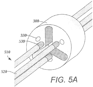
FIG. 5A is a schematic perspective view of one embodiment of a pre-electrode
300
before grinding. Although the pre-.electrode 300 of FIG 5A is disk-shaped, the
pre-electrode
300 may be formed of any suitable shape. The pre-electrode 300 includes a
plurality of
fixing lumens 330. The fixing lumens 330 allow for coupling or locking
portions of the pre-
electrode 300 to the lead body 110 (not shown) by ref owing a portion of the
lead body 110 to
allow it to pass through the fixing lumens 330. In some embodiments,
additional nixing
material similar to the lead body 110 is disposed within the fixing lumen 330.
The fixing
material may be composed of the same material or any other material capable of
ref owing
with the lead body 110. In some embodiments, portions of the pre-electrode 300
are further
bonded to the lead body I10 with a potting agent or adhesive such as epoxy.
FIG, 5A further illustrates conductors 510 being disposed through the
conductor
lumens 320. In some embodiments, the conductors 510 have a diameter
corresponding to the
diameter of the conductor lumens 320. As seen in FIG. 5A, a conductor 510 may
be coated
or wrapped with an insulator 520. The conductors 510 may also include ablated
portions
530. 'the ablated portions 530 allow for electrical coupling between the
conductor 5 10 and
the segmented electrode. in some embodiments, the portions of the conductors
510 are
14
CA 02798165 2012-11-01
WO 2011/159631 PCT/US2011/040229
disposed within the conductor lumens 320 of the pre-electrode 300 then welded
to a portion
of the pre-electrode 300, It will be understood than any other method suitable
for electrically
coupling a pre-electrode 300 to a conductor 510 may be used.
The pre-electrodes 300 may be formed larger in diameter than the lead body 1
I0.
Furthermore, the pre-electrodes 300 is yet undivided. In some embodiments, it
may be useful
or desirable to grind down the pre-electrode 300 to an appropriate diameter.
After the pre-
electrodes 300 have been ground down to the same level as the lead body 110,
the lead 100 is
isodiametric, having substantially the same diameter in all directions. The
result is a
substantially cylindrical lead 100 that is suitable for deep brain
stimulation, Grinding down
the pre-electrodes 300 is also capable of forming segmented electrodes 400
from the pre..
electrodes 300. Preferably, the pre-electrodes are ground after the pre-
electrodes are fixed
within the lead and coupled to the conductors.
FIG. SB is a schematic perspective view of the pre-electrode 300 of FIG. SA
after
grinding. In some embodi-nnetits, grinding the pre-electrode 300 results in
grinding portions
of the pre-electrode down to the divider 310, thus forming separate segmented
electrodes
400. As can be appreciated from FIG. 513, three segmented electrodes 400 are
formed at one
level of the lead body 110. A plurality of pre-electrodes 300 may be disposed
at
predetermined longitudinal levels of the lead body 100 to create leads having
variable
stimulation profiles. In some embodiments, the segmented electrodes 400 are
electrically
insulated from one another so that the stimulation directed to each segmented
electrode 400 is
independently-controlled.
In sore e other embodiments a pre-formed electrode frame may be used to form a
lÃad
having a plurality of segmented electrodes. FIG. 6A illustrates an electrode
frame 610
capable of housing a plurality of segmented electrodes. The electrode frame
610 may be
2S formed of a biocompatible, non-conducting material such as, for example, a
polymeric
material. Suitable polymeric materials include, but are not limited to,
polyetherethei ketone
col tetrafluoroeth y lene (e.g., Teflon"""), col imide, silicone,
olyurethan:es
polyether polyurethane, polycarbonate polyurethane, and silicone-polyurethane
copolymer.
The electrode frame 610 defines a plurality of electrode chambers 620 for
accepting a
plurality of segmerted electr=odes. The embodiment of FIG. 6A illustrates an
electrode frame
CA 02798165 2012-11-01
WO 2011/159631 PCT/US2011/040229
610 having three electrode chambers 620. It will be understood that the
electrode frame 610
may include any number of electrode chambers 620. In some embodiments, the
electrode
frame 610 includes one, two, thee, four, five, si:, seven, eight, nine, ten,
twelve, fourteen or
sixteen. electrode chambers 620. The electrode chambers 620 may also be
defined to house
segmented electrodes of the same or different shape or size. In at least some
embodiments,
the electrode chambers 620 are of the sar-ne shape and size. In some
embodiments, the
electrode chambers 620 fully enclose the segmented electrodes. The electrode
chambers 620
may be equally spaced about the electrode fi-arne 610. As illustrated, in some
embodiments,
the electrode frame 610 is C-shaped with an opening 630 configured for
coupling the
electrode frame 610 to a tubing as will be described in greater detail with
reference to FIG,
IOA. The electrode frame 610 may also include longitudinally extending grooves
640 on the
interior of the electrode frame 610. The grooves 640 may be configured to
house conductors
(not shown).
FIGS. 613 and 6C are schematic perspective views of a second and third
embodiment
of an electrode frame 6I0. As seen in FIGS. 613 and 6C, the electrode frames
610 may
include various electrode chambers 620 with a variety of different shapes. For
example, the
electrode frames 610 may be formed to house different-shaped segmented
electrodes. As
seen in FIG. 6C, in some embodiments, the electrode frame 610 lacks an opening
636, but is
formed slightly larger in diameter so as to be press fit over the lead body.
The segmented electrodes 710 may be formed of platinum, platinum-iridium,
iridium,
3161. stainless steel, tantalum, nitinol, a conductive polymer, or any other
suitable conductive
material, FIG. 7A is a schematic perspective view of one embodiment of a
segmented
electrode 710 corresponding to the electrode frame 610 of FIG. 6A, formed of
an elongate
member with an arched cross-section.. FIG. 713 is a schematic perspective view
of a second
embodiment of a segmented electrode 710 corresponding to the electrode frame
610 of FIC
6B. The segmented electrode 710 of FIG. 7I3 has a triangular cross-section.
FIG, 7C is a.
schematic perspective view of a third embodiment of a segmented electrode 7' 0
corresponding to the electrode frame 610 of FIG. 6C.. A seen in FIGS. 7A-C,
the segmented
electrodes 710 may be formed in a variety of shapes and sizes. In some
embodiments, the
segmented electrodes 710 are formed of elongate members having a circular,
ovoid,
rectangular, square, hexagonal, star-shaped, cruciform, trapezoidal, or a
patterned cross-
section (e.g. the cross-section shown in FIG. 7C). As seen in FIG-S. 7B and
7C, in some
16
CA 02798165 2012-11-01
WO 2011/159631 PCT/US2011/040229
embodiirrents, the segmented electrodes 71 0 include fastening features 720 to
aid in fastening
them to the electrode frame 610. For example, the fastening feature 720 may be
any of a
hole, key, seam, neek, shoulder, or rib.
FIG. 8 is a schematic perspective view of the segmented electrodes 710 o'311G.
7A
being inserted into the electrode chambers 620 of the electrode frame 610 of
FIG. 6A. As
seen in FIG. 8, the segmented electrode '710 may be press fit into the
electrode frame 610.
Other methods may be used to further affix or couple the segmented electrode
710 to the
electrode frame 610. For example, a potting agent or adhesive may be used to
affix the
segmented electrode 710 to the electrode frame 610. In at least some
embodiments, fastening
features 720, which correspond to the shape of the electrode chambers 620 are
useful for
maintaining P. proper fit between an electrode frame 610 and a segmented
electrode 710.
FIG, 9A is a schematic perspective view of one embodiment of a multi-lummen
tubing
900. The multi-lumen tubing 900 may be formed of any material or combination
of materials
used in forming a lead body. The multi-lumen tubing 900 may define a central
passage 910
configured to receive a stylet or other insertion, instrument. Though the
central passage 910 is
illustrated as a passage having a circular cross-section, any shaped central
passage 910 may
be formed. In some embodiments, the central passage 910 has a cross--section
corresponding
to the cross-section of a styiet. The .multi-lumen tubing 900 may define a
plurality of
longitudinally disposed conductor lumens 930. Any number of conductor lumens
930 ,nay
be defined within the multi--lumen tubing 900. In some embodiments, one, two,
three, four,
five, six, seven, eight, nine, ten, twelve or more conductor lumens 930 may be
defined by the
multi-lumen tubing 900. In some embodiments, the number of conductor lumens
930
corresponds to the number of electrodes that will be disposed on the tubing
900.
Portions of the multi--lumen tubing 900 may be removed to allow the coupling
of the
electrode frame 610. ljIG. 9B is a schematic perspective view of the multi-
lumen tubing 900
of FIG. 9A after ablating portions of the tubing 900. It will be understood
that any method
may be used for removing sections of multi-lumen tubing 900, For example,
portions of the
mutt lumen tubing 900 may be ground down to form slots 920. Alternatively,
slots 920 may.
also be formed by ablating the outer layer of the multi-lumen tubing 900
using, for example,
laser ablation. The resulting slots 920 may have dimensions corresponding to
the dimensions
17
CA 02798165 2012-11-01
WO 2011/159631 PCT/US2011/040229
of the electrode frame 610, so that the electrode frame 610 is coupleable to
the multi-lumen
tubing 900.
The electrode flames 610 may be coupled to the multi-lumen tubing 900. FIG. 1
OA is
a schematic perspective view of one embodiment of a lead consisting of a multi-
lumen tubing
900 and electrodes frames 610 disposed on the tubing 900. 1n some embodiments,
the
electrode frame 610 is flexible and configured so that the opening 630 of the
electrode frame
610 allows coupling to the multi-lumen tubing 900. In at least some other
embodiments, the
electrode frames 610 are configured to slide over the tubing 900. After
coupling the
electrode frames 610 and the multi-lurnert tubing 900, the tubing 900 and the
electrode frame
610 may be reflowed to form a lead 1000. In some embodiments, the tubing 900
and
electrode frames 610 are configured so that during the reflow process,
material is reflowed
through fixing lumens. By reflowing material through the fixing lumen, amore
reliable lead
1000 may be formed that is less prone to breakage and failure. individual
conductors may be
disposed through conductor lumens 930 and the grooves 640 and welded to the
individual
segmented electrodes 710.
As seen in FIG. 1013, portions ofthe outer surface of the electrode frame 610
may also
be removed (e.g., by ablation, grinding, and the like) to expose the segmented
electrode 710.
The outer surfaces of the electrode frames 610 may be removed in any pattern
as desired. For
example, in some embodiments, the outer surface of the electrode frame 610 is
removed at
one or more positions corresponding to each of the segmented electrodes 710
that are housed
within. In at least some embodi vents, an isodiametric lead is formed by
grinding the outer
surface of the electrode frame 610 and the lead body to the same diameter.
When the outer
surface of the electrode frame 610 is removed, the outer portion of the
electrode chamber 620
is removed to form an electrode cavity and the electrodes 710 are exposed at
the surface of
the lead. In at least some embodiments, each segmented electrode 710 is
electrically coupled
to an independent conductor (not shown) disposed within one of the lumens 930
so that each
segmented electrode 710 may be independently activated.
Liquid injected molding may also be used to create a lead array. FIG. I lA is
a
schematic perspective view of one embodiment of a segmented electrode 1110.
The
segmented electrode 1110 may be similar to those described in other
embodiments. In some
embodiments, the segmented electrode 1 110 is a rectangular portion having
legs and includes
18
CA 02798165 2012-11-01
WO 2011/159631 PCT/US2011/040229
flanges 1120. In some ermbodiments, each segmented': electrode l 110 includes
one flange
1120 on each side, though it will be understood that the segmented electrode
1110 may
include any number of flanges 1120.
FIG. 1 l B is a schematic perspective view of one embodiment of the segmented
electrode 1110 of FIG. 11A disposed in a carrier 1150. The carrier 1150 may be
a tray-like
member formed of any suitable insulative material capable of housing the
segmented
electrodes 111Ø Suitable materials for the carrier 1150 include, but are not
limited to
polymers (including plastics), composite materials, and the like. In some
embodiments, the
carrier 1150 is formed of silicone. The carrier 1150 includes apertures 1160
for receiving the
segmented electrodes 1110. In some embodiments, the apertures 1160 are formed
of the
same or different shapes and sizes. In some embodiments, the apertures 1 160
correspond to
the size and shape of the segmented electrodes l 110. Furthermore, the
apertures 1160 may
be formed in any pattern along the surface of the carrier 1150.
The carrier 1150 may also include side holes 1.1.70 to allow for the passage
of
conductors (not shown) to the segmented electrodes i 110. In some embodiments,
each
aperture 1160 corresponds to one or more side holes 1170. The side holes 1170
may be
formed in any edge or face of the carrier 1150. In some embodiments, as seen
in FIG. 11 II,
the side holes 1170 are aligned along one edge of the carrier 1150. It will be
understood that
any number of side holes 1170 may be formed in the carrier 1150 in any pattern
or alignment,
such as in multiple roles.
As seen in FiG. 11 B, the segmented electrodes 1.1 10 may be press fit into
the
apertures 1160 of the carrier 1150. in some embodiments, the segmented
electrodes 1110 are
locked in place by the flanges 1120 or. the sides. The flanges 1120 may be
configured to
mate with a side of the apertures 1160. With the segmented electrodes 1110
locked in place,
the carrier 1150 may be wrapped around a mandrel and reflowed to form a lead
as seen in
FIG. 11C.
In another embodiment, a tubing 1200 similar to that of the multi-lumen tubing
900 is
provided. The tubing 1200 may be provided with a plurality of conductor lumens
1220. The
tubing 1200 may also include a central passage 1210 configured fir receiving
an insertion
19
CA 02798165 2012-11-01
WO 2011/159631 PCT/US2011/040229
instrument such as a st,,,let. Pre-welded electrode tubes 1250 may be disposed
within the
conductor lumens 1220.
1,10r. 12A is a schematic perspective view of one embodiment of a tubing 1200
having
electrode tubes 1250. The electrode tubes 1250 may be short in length and
inserted only in
conductor lumens on sides of the multi-lumen tubing 1200 where stimulation is
desired. In
some embodiments, electrodes tubes 1250 are inserted only at the extremities
of the multi-
lumen tubing 1200. The electrode tubes 1250 may be press fit within the multi-
lumen tubing
1200 to avoid slippage during manufacture and usage. In some embodiments,
additional
methods may be used to enhance coupling between the electrodes tubes 1250 and
the m lti-
lumen tubing 1200, such as, for example, the use of epoxy within the conductor
lumens 1220.
In some embodiment, the electrode tubes 1250 have a groove 1270 that may be
useful
in coupling the electrode tube 1250 to the tubing 1200. As seen in FIG. 12B,
the groove
1270 may be longitudinally positioned along the electrode tube 1250. Moreover,
the
conductor lumen 1220 may be defined to have a cross-sectional shape that will
Aid 1.2,
fastening the electrode tube 1250 to the tubing 1200. It will be understood
that any number
of grooves 1270 may be positioned on the electrode tube 1250.
With the electrode tubes 1250 disposed within the multi-lumen tubing 1200,
techniques such as grinding or ablation may be used to expose portions o the
electrode tubes
1250 by removing portions of the outer surface of the tubing 1200. As seen in
FIG, 12A, the
locations of ablation 1260 may be chosen in any pattern as desired.
Modifications of these methods are possible. For example, one or more
combinations
of the above methods may be used to form a lead as desired. In some
embodiments, these
,methods are used with lead constructions other than deep brain stimulation
leads.
The above specification, examples and data provide a description of the
manufacture
and use of the composition of the invention. Since many embodiments of the
invention can
be made without departing from the spirit and scope o{'the invention, the
invention also
resides in the claims hereinafter appended.