Note: Descriptions are shown in the official language in which they were submitted.
CA 02798227 2012-11-01
WO 2011/139358 PCT/US2011/000772
UNIVERSAL STORAGE AND SHELVING SYSTEM
BACKGROUND OF THE INVENTION
Field of the Invention (Technical Field):
The present invention relates to shelf storage, particularly to shelving
systems for
installation into spaces in residential homes, apartments, or other buildings,
and specifically to
a shelving and storage system that is lightweight yet durable, and which is
simple and easily
installed.
Background Art:
Built-in shelves have been commonplace for centuries. In recent decades, there
has
been an increase in popularity of modular-type shelving systems, devised for
purchase at retail
home-improvement and hardware stores for installation by the do-it-yourself
person, including
homeowners and small-business persons. However, many such systems are heavy
and bulky
even when unassembled and packaged for sale, making it difficult for a typical
person to
transport the system from the point of purchase to another location for
installation. Also, many
known systems are of limited versatility and/or are complicated to install,
particularly if power
tools are required.
Many commonly encountered do-it-yourself shelf systems are fabricated from
dense
"particle board" composites, which are quite heavy when packaged for sale.
Also known are
systems using coated wire shelving which may be adapted to a particular closet
by the user.
Often, the wire shelving is cut to fit within the closet. The installation of
wire shelving
frequently involves the drilling of many holes in the wall(s). Specialized
small clips often
must be attached the wall using screws inserted into the pre-drilled holes.
Special clips or
fasteners also may be required to interconnect the various elements of the
system. The rough
edges of the cut wires, if not properly covered, can snag and ruin clothing.
Also, many known modular or simple shelving systems require that the ends of
the
shelves be attached to supporting surfaces (e.g., the "side walls" of a
closet) perpendicular to
the main supporting surface (e.g., the "back wall" of a closet), and thus are
not suited for use
on a single open wall, such as the wall of a laundry or bed room. This
requirement that there
be three walls (a back wall and two parallel "side" walls perpendicular to the
back wall) for
mounting a shelving system is even more frequently imposed if it is desired
also to have
1
CA 02798227 2012-11-01
WO 2011/139358 PCT/US2011/000772
horizontal clothes rods in conjunction with the shelves; in many known systems
including
clothes hanger rods, each end of a clothes rod must be securely fastened to a
perpendicular side
wall.
Other shelving systems known in the art require that support be provided to
the system
from the floor. Thus, many systems have base components that must be placed on
the floor, or
have vertical poles at the front of the system which extend to the floor to
stabilize the system.
This is undesirable in circumstances where there is to be other item(s) (e.g.,
a small bureau,
clothes washer/dryer, etc.) situated on the floor beneath the shelving system.
Some known systems are flimsy, and offer insufficient structural integrity to
support
significant loads.
But perhaps the largest drawback to conventional shelving systems is that they
tend to
be difficult to install because they feature many small parts that must be
identified, organized,
and kept track of during installation. Sometimes many or specialized tools are
required. The
typical homeowner or small businessperson without prior experience with a
particular system
can be baffled or frustrated by installation.
Thus, there remains an unmet need for a do-it-yourself shelving system, for
use by
ordinary persons such as homeowners and landlords, which is easy and intuitive
to install,
employs a minimal number of small or specialized parts, and which yet is
versatile and sturdy.
A reliable and strong shelving system that also does not depend on floor
support also is
needed. Further, there is a need for a shelving system that in the un-
assembled state is
comparatively lightweight and compact so that it is relatively easy for the
homeowner or other
individual to transport from the point of purchase to the point of
installation. Also, a
lightweight modular shelving system is more affordably shipped and stocked by
wholesalers
and retailers. Against the foregoing background, the present invention was
developed.
SUMMARY OF THE INVENTION (DISCLOSURE OF THE INVENTION)
There is disclosed hereby an innovative shelving system. The system is well-
suited for
installation in closets, pantries, and other enclosed spaces, but is not
limited to such installation
locations. The system according to this disclosure may be installed with ease
upon practically
2
CA 02798227 2012-11-01
WO 2011/139358 PCT/US2011/000772
any wall in a residence or commercial establishment. Notably, it is not a
requirement for
installation of the system that there be sidewalls, such as the side walls of
a closet, at the ends
of the shelves upon which to secure the ends of the system shelves. The
disclosed system is
modular, and simple to use and install. It is devised to be lightweight to
transport prior to
assembly, yet reliable and attractive after installation. The apparatus
according to this
disclosure potentially may be installed by a single user, using simple tools.
It is adaptable for
installation at a length selected by the user, and thus is readily adapted for
installation in
enclosed spaces (such as closets) of different widths, and is versatile to
permit a variety of
shelf and/or wardrobe hanger rod configurations as may be selected by the
user.
One embodiment of the system according to this disclosure has 29 parts that
weigh less
than all conventional aftermarket-type shelving systems. The kit provided
weighs, for
example, only about 20 kg. An advantage thus is that the unassembled kit for
the system
potentially may be carried from within a retail store point of purchase to a
purchaser's motor
vehicle in the parking lot, by a single person with little or no assistance.
The installed system
is engineered to carry total loads of up to, for example, about 820 kg.
There is disclosed a simple and versatile storage and shelving system. A
plurality of
specialized, sturdy, lightweight, integrally molded main panels are provided,
which may be
hung upon a hanger track mounted upon a vertical wall. The main panels are
specially shaped
to define shelf ledges therein upon which shelves may be easily but securely
placed. There are
defined in the fronts of the panels one or more wardrobe hooks into which
wardrobe rods may
be placed. Special hook bodies for the wardrobe rods and flange elements for
the panel
wardrobe hooks promote secure engagement of the wardrobe rods with respective
pairs of
panels to promote the stability and security of a completely installed system.
Auxiliary panels
may be removably connected to the bottoms of main panels to increase
versatility of a given
system by permitting the additional of more shelves or drawers.
Most of the components are composed of either lightweight, impact-resistant,
polycarbonate plastic or ABS plastic, and are devised to be affordably
manufactured and
simply assembled and installed. The system features at least two, preferably a
plurality, of
vertical panel components which are mounted onto a wall. The panels form the
"foundation"
of the versatile system. The panels have wardrobe rod hooks to receive and
support wardrobe
rods, as well as narrow ledges upon which the ends of shelf elements rest. In
one possible and
3
CA 02798227 2012-11-01
WO 2011/139358 PCT/US2011/000772
example embodiment employing four modular closet panels, the wardrobe rods can
hang
clothes in twelve different areas and the shelves can also be situated in
twelve different
locations. Each modular panel member is mounted to a wall (for example the
back wall of a
closet or pantry) by means of a J-shaped hanger track running horizontally
along the wall. The
hanger track engages with a complementary hook on the top back of each panel.
Also, there is
provided an aperture flange at the bottom of each panel to permit the bottom
of each panel to
be secured to the wall by means of a conventional drywall screw. The panels
are
advantageously bilaterally symmetrical and universal, so that it does not
matter which side of a
panel faces right or left in installation, nor does it matter which panel is
placed at a side or end,
versus in the middle, of the installation space or location.
A primary object of the present invention is to provide a lightweight modular
shelving
system, sufficiently lightweight so to be carried in its unassembled state by
a single person.
Primary advantages of the present system are that it is simple to install,
durable, and
relatively affordable.
Other objects, features, and characteristics and further scope of
applicability of the
present invention, as well as the methods of use and functions of the various
components of the
structure, and the combination of parts and economies of manufacture will
become more
apparent upon a consideration of the detailed description that follows, and
the appended claims
with reference to the accompanying drawings, all of which form a part of this
specification
wherein like reference numerals designate corresponding parts in the various
figures.
BRIEF DESCRIPTION OF THE DRAWINGS
The accompanying drawings, which are incorporated into and form a part of the
specification, illustrate several embodiments of the present invention and,
together with the
description, serve to explain the principles of the invention. The drawings
are only for the
purpose of illustrating preferred embodiments of the invention, and are not to
be construed as
limiting the invention. Further, all dimensions seen in the drawings are
exemplary and not
limiting of the scope of the invention. In the drawings:
4
CA 02798227 2012-11-01
WO 2011/139358 PCT/US2011/000772
Fig. I is a perspective front view, from above, of an exemplary embodiment of
a
shelving system according to the present disclosure, illustrating the system
installed relative to
the walls of a closet;
Fig. 2A is a right side view of a main panel member usable in the system
according to
the present disclosure;
Fig. 2B is a front view of the panel seen in Fig. 2A;
Fig. 2C is an enlarged side view of a broken-away portion of the panel seen in
Fig. 2A,
depicting details of the wardrobe hook feature;
Fig. 3A is a perspective side view of a possible unitary shelf component of
the system
according to the present disclosure, showing a pair of lock notches on
opposing sides of the
shelf;
Fig. 3B is a side or end view of the shelf component seen in Fig. 3A;
Fig. 4A is a front view of a hanger track component of the system according to
the
present disclosure;
Fig. 4B is an enlarged side view of the hanger track seen in Fig. 4A;
Fig. 5A is an enlarged perspective view of a wardrobe rod component of the
system
according to the present disclosure, and a hook body component of the system
insertable into
an open end of the wardrobe rod;
Fig. 5B is an enlarged side or end view of the hook body component seen in
Fig. 5A;
Fig. 5C is a front view of a hook body component seen in Fig. 513;
Fig. 5D is a top view of the hook body component seen in Fig. 513;
Fig. 5E is a perspective view, from above, of the hook body component seen in
Figs. 5B-5D;
Fig. 6A is an enlarged front view of a spacer usable in conjunction with the
hook body
component seen in Figs. 5A-E;
Fig. 6B is a side view of the spacer depicted in Fig. 6A;
Fig. 6C is a front perspective view of the spacer seen in Fig. 6B;
Fig. 7A is an end view of the main body of an adjustable shelf according to
the system
of the present disclosure;
Fig. 7B is a bottom view of the adjustable shelf main body seen in Fig. 7A;
Fig. 7C is a side view of the adjustable shelf main body seen in Fig. 7B;
Fig. 7D is an enlarged end view of a portion A-A of the adjustable main shelf
body
depicted in Fig. 7A;
Fig. 7E is a perspective view of the adjustable main shelf body seen in Figs.
7A-C;
5
CA 02798227 2012-11-01
WO 2011/139358 PCT/US2011/000772
Fig. 8A is an end view of a shelf extender component usable in conjunction
with the
adjustable main shelf body seen in Figs. 7A-E;
Fig. 8B is a bottom view of the shelf extender component seen in Fig. 8A;
Fig. 8C is a side view of the shelf extender component seen in Fig. 8B;
Fig. 8D is an enlarged side view of a portion A-A of the shelf extender
component
depicted in Fig. 8C;
Fig. 8E is a perspective view, from above, of the shelf extender component
seen in
Figs. 8A-C;
Fig. 9 is a perspective view, from above, of the main shelf body of Figs. 7A-E
slidably
coupled with the shelf extender of Figs. 8A-E, to show an adjustable shelf
assembly according
to the present system;
Fig. IOA is a left side view, relatively enlarged, of the shelf clip component
of the
shelving system according to the present disclosure, usable in connection with
the adjustable
shelf assembly seen in Fig. 9;
Fig. I OB is a front view of the shelf clip component seen in Fig. 10A;
Fig. 1 OC is a top view of the shelf clip component seen in Fig. 10B;
Fig. I OD is a perspective view, from above, of the left side of the shelf
clip component
seen in Figs. l0A-C;
Fig. I I A is an enlarged side view of the hook body depicted in Figs. 5A-E,
showing
how the spacer seen in Figs. 6A-C is engageable therewith;
Fig. 1 1 B is an enlarged side view, showing the spacer in place upon the hook
body,
which is then insertable into an open end of a wardrobe rod;
Fig. 12A is an exploded perspective view of an overall system according to the
present
disclosure and similar to the view of Fig. 1, showing the optional use of a
pair of auxiliary
panels for the installation of an optional drawer;
Fig. 12B is a right side view of an auxiliary panel, enlarged relative to Fig.
12A,
according to the present disclosure;
Fig. 12C is a front view of the auxiliary panel seen in Fig. 12B;
Fig. 12D is an enlarged view of a portion of the top edge of the auxiliary
panel depicted
in Fig. 12C; and
Fig. 12E is a front perspective view, from above, of the auxiliary panel seen
in
Figs. 12A-D.
6
CA 02798227 2012-11-01
WO 2011/139358 PCT/US2011/000772
Like numbers refer to like elements throughout the several drawings and views;
the
various views are not necessarily to scale relative to one another.
DESCRIPTION OF THE PREFERRED EMBODIMENTS
(BEST MODES FOR CARRYING OUT THE INVENTION)
In this disclosure, reference is made to the accompanying drawings which form
a part
hereof, and which illustrate specific embodiments and methods by which the
invention may be
practiced. These embodiments are described herein to enable those skilled in
the art to practice
the invention, but is shall be evident that other embodiments may be used and
that the
configuration and details of structure may be modified without departing from
the spirit and
scope of the present invention. Therefore, the following detailed description
must not be
construed as limiting. The scope of the present invention is defined by the
appended claims.
The elements and components of the disclosed shelving and storage apparatus
and
system are adjustably arranged for adaptation to various storage and
organizational needs and
spaces, including but not limited to storage areas including closets, rooms in
commercial
establishments, and rooms in residential dwellings, including basements,
garages, kitchen
pantries, laundry rooms, garages, and the like. The shelving system can have
many variations
of its components including various combinations of the vertical panels,
shelves, and wardrobe
rods, such as configurations and installations where a single component is
provided with other
components, or configurations where multiple components are provided.
There is disclosed hereby an innovative shelving system for installation on a
single open
wall, as well as in more enclosed storage spaces such as closets and pantries.
It is modular,
and simple to use and install. The apparatus system is devised to be
lightweight to transport
prior to assembly, yet reliable and attractive after installation. The
apparatus according to this
disclosure potentially may be installed by a single user, using a minimal
number of simple
tools. The system according to this disclosure may be mounted on practically
any vertical
wall. It is adaptable for installation in closets of different widths, and is
versatile to permit a
variety of shelf and wardrobe hanger rod configurations as may be selected by
the user.
Nevertheless, it shall be understood that system installation is not limited
to installation within
enclosed or confined spaces such as closets or pantries. Desirable
installation may be upon a
wall within an open wall or garage or the like.
7
CA 02798227 2012-11-01
WO 2011/139358 PCT/US2011/000772
For example, a kit according to the system according to this disclosure has 29
parts that
weigh less than all conventional aftermarket-type closet shelving systems. The
kit provided
weighs, for example, only about 20 kg. An advantage thus is that the
unassembled kit for the
system potentially may be carried from within a retail store point of purchase
to a purchaser's
motor vehicle in the parking lot, by a single person with little or no
assistance. The installed
system is engineered to carry total loads of up to, for example, about 820 kg.
Most of the components are composed of either lightweight, impact-resistant,
polycarbonate plastic or ABS plastic, and are devised to be affordably
manufactured and
simply assembled and installed. The system features at least two, preferably a
plurality, of
vertical panel components which are mounted into a wall. The modular vertical
panels form
the "foundation" of the versatile system. The vertical panels have wardrobe
rod hooks to
receive and support wardrobe rods, as well as narrow (e.g. approximately 1.0
cm) ledges upon
which the ends of shelf elements rest. In one embodiment employing four
vertical panels, the
wardrobe rods can hang clothes in twelve different areas and the shelves can
also be situated in
twelve different locations. Each vertical panel member is mounted to the wall
by means of a
J-track hanger mounted horizontally along the wall, which engages with a
complementary
hook on the top back of each panel. Also, there is provided an aperture flange
at the bottom of
each panel to permit the bottom of each panel to be secured to the wall by
means of a
conventional drywall screw. Advantageously, the panels are bilaterally
symmetrical and
universal, so that it does not matter which side of a panel faces right or
left in the installation,
nor does it matter which panel is placed at a side versus in the middle of an
installed system.
In the disclosure that follows, the terms "up" and "down" have their ordinary
meaning
in relation to gravity. "Right" and "left," "top" and "bottom," and "back" (or
"rear") and
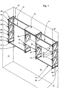
"front" may be best understood in the reference of drawing Fig. 1, showing a
perspective front
view of an example of an installed system upon a back wall 15 and between a
right side
wall 11 at the right side of the figure and a left side wall 11 at the left
side of the figure, with a
floor seen between the bottoms of the side walls. "Integral" or "integrally"
means a complete
unit or unitary whole, not composed of separate parts fastened together.
Fig. 1 shows the apparatus according to the present disclosure installed
within a closet.
Again, it is understood that the apparatus is well-suited for use within a
closet, but is not so
limited. In a preferred embodiment of the system, four vertical panels 10 are
mounted within
8
CA 02798227 2012-11-01
WO 2011/139358 PCT/US2011/000772
the space, substantially parallel to each other. In the closet installation
shown, the panels 10
are likewise parallel to the closet side walls 11. An advantage of the present
system, however,
is that closet sidewalls 11 are not required to be present to support the
system. In the
embodiment illustrated, four vertical panels 10 are shown; it shall be
recognized those skilled
in the art, however, that the number of panels 10 can be varied to adapt the
system to
installation spaces or locations of different widths and to permit the user to
select a particular
system configuration suited to her personal preference. Thus, it is possible
for a shelving
system installed according to the present disclosure to feature as few as two,
and perhaps as
many as six or more vertical panel members 10; a plurality of panels may be
installed serially
in parallel in numbers to suit the width of the desired installation, whether
it be upon a single
wall of a living room, garage, commercial or professional office, work or
sales room, or within
a more confined space such as a closet according to the user's own customized
plan or choice.
The vertical panels are fabricated from a lightweight rigid plastic, for
preferred
example, a molded lightweight polycarbonate plastic, and may be clear,
frosted, or colored,
with a pleasant aesthetic finish. Polycarbonate main panels are preferred, as
they are readily
molded, and thermoformed in to strong, yet aesthetic configurations. Further,
panels of
molded polycarbonate are strong, yet lightweight (e.g., approximately 1.20-
1.22 g/cm3).
Panels 10 according to the present disclosure may be manufactured by extrusion
into sheets,
followed by further fabrication into other shapes using thermoforming or other
secondary
fabrication techniques, such as by bending and routing. Alternatively, as
known in the art of
plastics fabrication, polycarbonate also may be manipulated by injection
molding.
Referring still to the embodiment of Fig. 1 it is seen that two outside panels
10 are
mounted against the closet side walls 11, while two (or more) inside panels
are situated parallel
between the outside panels. The outside panels 10, however, need not be
attached to the closet
side walls 11, and installation of the system progresses the same regardless
whether any
sidewalls 11 are present. The spacing distance between the inside panels may
be a
predetermined fixed distance to accommodate shelve(s) 18 that are non-
adjustable in size;
alternatively, it is possible without departing from the scope of the
invention for the relative
separation distances between the various panels 10 to be independently
selected by the user.
The distances between the inside panels 10 and the outside panels, may be
selectable by the
user to accommodate her particular system configuration plan. Each of the
vertical panels 10
is installed so that its wardrobe rod hooks 22 face forward, toward the user,
as suggested by
Fig. 1.
9
CA 02798227 2012-11-01
WO 2011/139358 PCT/US2011/000772
All the vertical panels 10 in a given kit according to the system are
identical, thus
promoting facile installation of the system. Further, the panels 10 are
bilaterally symmetrical,
the right and left hand sides of each panel being substantially identical
(except to be reverse or
"mirror" images of each other). This also promotes easy installation, as the
user merely
installs all panels 10 with their respective front edges facing outward toward
the user, but in
any order; no particular panel 10 need be installed first, or last, etc.
Further, the integrated
shelving ledges and tapered frame members (to be further described) on each
panel 10 indicate
intuitively to the user the "top" and "bottom" of each panel.
The main panel 10 seen in Figs. 2A and 2B is exemplary and preferred, but not
limiting.
It is immediately appreciated by one skilled in the art that the panels 10 are
modular, and can
be fabricated in a variety of sizes. Referring to the embodiment of Figs. 2A-
B, the panel 10
may be, for example only, between about 100 cm and 115 cm high, and between
about 30 cm
and about 40 cm deep front-to-back). The maximum thickness of a panel 10 may
be, again by
way of example, between approximately 2.5 cm and approximately 4.0 cm.
The panel embodiment seen in the figures is configured to define three
integrated cells
or sections, each section being bounded on the top and the bottom by a pair of
shelf ledges 26,
and on the front and back by the frame flanges 25. There also is shown the
optional or
preferred bottom section 28 depending from the bottom of the lowermost cell.
The sections or
cells in the preferred embodiment each has an aesthetic, weight-reducing
aperture 31 defined
though its web 29.
It is to be understood that a main panel 10 according to the present
disclosure is not
limited to having three main cells or "sections" as described immediately
above in reference to
Fig. 2A. An advantage of the invention is its modularity. Accordingly, a
single main panel 10
may have as few as one section having a web 29 bound by a shelf ledge above
and a shelf
ledge below, and a back and a front, the front having the ingle rod hook 22
for the panel. OF
course, every panel, regardless of the number of cells or sections it
manifests, features a track
hook notch 36 in the back of its upper-most cell or section. Another panel
accordingly can be
relatively larger, in vertical extent, by the provision of one or more
essentially duplicate
sections or cells integrally formed with, and depending serially down from,
the top-most
section having the hook notch 36. A given panel 10 may have therefore and
according to the
CA 02798227 2012-11-01
WO 2011/139358 PCT/US2011/000772
invention, one or more, up to (for example five or six) panel sections such as
the three sections
seen in Figs. 2A-B. A bottom section 28 optionally but preferably is provide
as the bottom-
most section in any panel 10, as seen in the drawing figures.
The panels 10 are attached to the wall 15 (such as, but not necessarily, a
back wall of a
closet) by means of a hanger track 16 secured upon the wall. The hanger track
16 shall be
described further hereinafter. An upper portion of each vertical panel 10
engages with the
hanger track 16. Also, an aperture preferably is provided at a bottom portion
of each panel 10,
through which a drywall screw or the like can be advanced to secure the bottom
of each panel
to the wall 15.
Continued reference to Fig. 1 shows that a selected plurality of wardrobe rods
14 are
placed into selected associated pairs of rod hooks 22 provided on the front
edges of the
panels 10. The user can choose the number (four illustrated in Fig. 1) of
wardrobe rods 14 to
utilize in a particular system installation, and can engage them at various
different positions
upon the panels 10. In the embodiment seen in Fig. 1, there are sixteen rod
hooks 22 offering
twelve associated pairs of hooks, permitting the user to choose a variety of
different numbers
and height positions of wardrobe rods 14 for installation in the system.
An advantage of the system is that the wardrobe hooks 22 are defined into the
fronts of
the panels 10, that is, the hooks are offset rearward into the web portion 29
of the panel 10,
rather than extending out frontward from the front of the panel. This
configuration of the
wardrobe hooks 22 not only is more aesthetic, but less obtrusive without
sacrificing
functionality. Further, the system is sturdier with such recessed hooks 22.
Conventional
clothes rod hooks that project a substantial distance out from the front of a
shelf act as
undesirable lever arms. When a clothes rod is disposed on such conventional
forward-
thrusting rod hooks, and a rod placed thereon and loaded with many garments,
the collective
weight of the garments is leveraged by and through the hook to generate a
substantial upward
force upon the shelf; further, the weight of the garments typically is
relatively concentrated at a
point cantilevered from the front of the shelf, a condition which may promote
failure of the
hook. In the presently disclosed system, in contrast, the collective weight of
the garments
upon a wardrobe rod 14 is much better distributed and dissipated, as it is
imposed not upon a
cantilever but instead downwardly upon the complete body (including the web 29
between
11
CA 02798227 2012-11-01
WO 2011/139358 PCT/US2011/000772
front and back frame flanges 25) of a panel 10. The advantage is doubled by
the use of two
panels 10 used to support a given wardrobe rod 14.
Also, a plurality of shelf components may be selectively disposed between and
upon the
panels 10. Seen in Fig. I is a fixed-size shelf 18 situated at a top-most
position between a pair
of inside shelves 10, and an adjustable shelf assembly 20 placed at an
intermediate height
position between an inside panel and a left-side outside panel 10. There also
is shown a second
fixed-size shelf 18 placed below the upper-most first one, at one of two
intermediate-height
positions defined between the two inside panels. As shall be described further
hereinafter,
each vertical panel 10 has integrally molded therein, on both its left and its
right side, a
plurality of shelf ledges. In the embodiment depicted in Fig. 1, each panel 10
features four
ledges on each side of the panel. Each end of a shelf 18, 20, may be rested
upon a
corresponding shelf ledge on a respective panel 10 to support the self 18 or
20 in horizontal
position. In the embodiment seen in Fig. 1, there are twelve pairs of
associated shelf ledges on
four panels 10, permitting the user to choose a variety of different numbers
and height
positions of shelf components 18 and/or 20 for installation in the system. (In
Fig. 1, the shelf
ledges on the outside sides or faces of the two outside panels 10 are not in
use.)
Combined reference is made to Figs. 2A and 2B, illustrating in more detail a
vertical
panel 10 according to the present system. Description of one vertical panel 10
serves
substantially to describe all the panels (e.g., each of panels 10 seen in Fig.
1), as all the panels
preferably are molded to be substantially identical. This is one of the
advantages of the present
apparatus; the panels of a given kit or system preferably are all the same
size and shape, and
preferably are bilaterally symmetrical about their principal definitional
plane. Thus, Fig. 2A
shows the right side of an exemplary panel 10; the left side of the panel 10
seen in Fig. 2A is
the same as the right side (except being a reversed "mirror image"). For this
reason, any
particular panel 10 can be situated at any selected lateral location within a
particular
installation. Any panel 10 can serve as an "inside" panel in an installation
having three or
more panels, and any panel can function as the "outside" or end panel in any
installation. Also,
for example, either side of a panel 10 can be placed against a closet side
wall 11.
This very desirable universality of the panels 10 is promoted by their
symmetry.
Fig. 2B shows a front edge view of an embodiment of a panel 10. An imaginary
central plane
(perpendicular to the plane of the paper) is perceived in Fig. 2B, and runs
from the top to the
12
CA 02798227 2012-11-01
WO 2011/139358 PCT/US2011/000772
bottom of the panel to define the panel's formational plane of symmetry.
Because the left side
of the panel is the same as the right side, any panel can be used in any
location in the system.
The need to place panels in any particular order (right to left) along the
wall is eliminated. The
user intuitively places the front of the panel forward facing him, and readily
senses "up" from
"down" on the panel.
In one preferred embodiment, a panel 10 has a generally rectangular exterior
shape
when viewed from the side as seen in Fig. 2A. A panel 10 preferably has a
generally planar,
flat back 24 that can be placed flush against the wall 15 upon which the panel
is installed. The
front edge of a panel also typically (but not necessarily) is generally flat
and rectilinear, except
where periodically interrupted by the concave nocks associated with the
wardrobe rod
hooks 22 as seen in Fig. 2A. The back, front, and bottom edges, and optionally
the top edge,
of the panel 10 preferably feature integrally molded, thickened frame flanges
25 to lend
additional stiffness and structural integrity and stability to the overall
panel. The top of the
panel 10 is mostly defined (and rigidized somewhat) by the thickness provided
by the presence
of a pair of horizontal, laterally projecting shelf ledges 26 to be further
described. Each
vertical panel 10 has at least two, and more preferably four or six, and most
preferably eight,
horizontal shelf ledges 26 molded integrally with the panel 10. The shelf
ledges 26 occur in
pairs, at selected height positions on the panel 10, with ledges from a given
pair disposed on
opposite sides of the panel.
The panel 10 has a central web 29 that extends generally throughout its height
and front-
to-back depth, to provide load-bearing strength to the panel. As seen in Fig.
2A, the web 29
may define therein one or more apertures 31 there-through, of comparatively
large size and at
selected positions, which apertures 31 reduce the weight of the panel without
unduly
compromising its structural stability. The oval apertures 31 as shown in the
drawing figures
also are aesthetic, and offer additional locations on a panel where a user my
drape or hang a
lightweight item (e.g. a necktie or small bath towel) in an installed system.
Further understanding of the shelf ledges 26 is had with combined reference to
Figs. 1, 2A and 2B. Fig. 2B is a front view of the panel 10 seen in Fig. 2A.
In the embodiment
shown, the panel 10 has eight shelf ledges 26 molded in the sides thereof;
four associated pairs,
approximately equi-spaced vertically at four heights above the bottom of the
panel. There are
four ledges 26L provided on the left side of the panel 10, and four ledges 26L
provided on the
13
CA 02798227 2012-11-01
WO 2011/139358 PCT/US2011/000772
right side of the panel. Each ledge 26 extends laterally outward from the web
29 a suitable
distance (e.g., between approximately 0.5 cm and approximately 2.0 cm) to
provide a
substantial, reliable, supporting surface upon which the end of a shelf
element (18, 20) can be
laid.
Continuing reference to Figs. 1, 2A, and 2B illustrates that each vertical
reinforcing
frame flange 25 is tapered downward (as viewed from the front or back),
decreasing
progressively in lateral extent as it descends from a pair of shelf ledges
above the flange and
approaches ledges below the frame flange. Thus, as best seen in Figs. 2B, at
their respective
tops, the stabilizing frame flanges 25 have their maximum lateral extents,
corresponding
approximately to the width of the pair of shelf ledges (left--side ledge 26L),
(right-side
ledge 26R) at the top of the flange. The width of each flange 25 decreases
toward the bottom
of the flange; at the bottom of a vertical flange, its width effectively
equals the lateral thickness
of the corresponding web 29 as the flange 29 essentially "disappears" into the
web 29 just
above a second, lower pair of shelf ledges 26L, 26R. This downward tapering of
flanges 25 on
the front and back of each section of a panel 10 decreases each flange's
lateral extent as the
flange descends from an upper shelf ledge to approach a lower shelf ledge
below the frame
flange; thus there is a vertical gap 37 defined between the bottom of a flange
25 and a lower
shelf ledge. The absence of laterally projecting frame flanges 25, in the
vicinity immediately
above the ledges 26, permits the end of a shelf 18 or 20 to be lowered into
place upon a
particular ledge 26 without interference from a laterally projecting frame 25.
The frame flanges 25 thus reinforce the panel, but do not interfere with its
use. The
gradual taper of those flanges located at the back and front of each panel
results in the bottom
of each vertical flange is a modest distance above the shelf ledge 26R or 26L
situated there
below, providing a vertical gap between the flange and the shelf ledge to
facilitate the
placement of an end of a shelf 18 or 20 upon the ledge.
Figs. 4A and 4B illustrate a version of a hanger track 16 according to the
presently
disclosed system. The hanger track 16 may be fabricated from, for example,
fifteen gauge
steel, although other suitably stiff, durable compositions may also be
employed. The hang
track 16 is mounted, as for example with drywall screws (with mounting
toggles, and/or into
wall studs) horizontally at a user-selected height across the wall 15 as seen
in Fig. 1. Fig. 4A
shows that the shank 32 of the hanger track 26 is provided with a series of
mounting holes 34
14
CA 02798227 2012-11-01
WO 2011/139358 PCT/US2011/000772
uniformly distributed along the length of the track. The holes 34 are sized to
provide passage
of ordinary drywall screws or like fasteners for mounting the track 26 upon
the wall. Adjacent
holes 34 are separated by a modest spacing distance, so to maximize the
opportunity for
fasteners disposed through a given hole to be screwed into a supporting wall
stud beneath
drywall of the wall 15. The hanger track 16 may initially be about 120 cm
long, for illustrative
example, but may be cut to a user-selected length to suit the particular
installation
configuration, or to fit the width dimension of a pantry or closet. The hole
pattern of holes 34
may be set at approximately 2.5 cm spacing to promote the track mounting
screws or other
fasteners to be locatable so as to be driven into a wall stud.
As seen in Figs. 4A and 4B, particularly Fig. 4B, the hanger track 16 is bent
to define a
J-shaped hook, in end profile, preferably throughout its axial length. The
hook portion 33 is
engageable into a complementary hook notch 36 near the top of the back edge 24
of each
panel 10.
Reference is returned to Fig. 2A. The back edge 24 of each panel 10 is
provided, near
the top of the panel, with an indented hook notch 36 defined into the panel.
The shape and size
of the interior contours of the hook notch 36 are substantially complementary
with the contours
of the hook 33 portion of the hanger track 16. The panel's hook notch 36
preferably is
reinforced on either lateral side by frame flange elements 25 continued from
the back 24 of the
panel. The flange 25 around the hook notch 36 is sized to have a contour
generally
corresponding to the generally J-shaped configuration of the hook notch 36
itself, as seen in the
upper portion of Fig. 2A. Thus, when a panel 10 is lifted into place, the user
permits the
hook 33 of the previously installed hanger track 16 to engage securely (but
removably, as by
gravity) into the panel's hook notch 36. With the hook notch 36 engaged over
the hook 33, the
panel 10 hangs reliably from the hanger track 16 which is fixed to the wall
15.
Figs. 2A and 2B also show that there is a small attaching flange 38 which
depends
downward from the bottom of the back 24 of each panel 10. This vertical bottom
flange 38
may be penetrated by a screw aperture (Fig. 2B). To install reliably a panel
10 upon a wall 15,
a drywall screw or equivalent suitable fastener (not shown) is driven through
the aperture into
the wall 15 (preferably into a wall stud). This preferable use of a lower
fastener reduces any
tendency for a panel 10 to "swing" side-to-side upon the track 16.
CA 02798227 2012-11-01
WO 2011/139358 PCT/US2011/000772
A useful feature of the presently disclosed system is the specialized wardrobe
rod
hooks 22 defined in the front of each panel 10. Figs. I and 2A show that one
or more
wardrobe rod hooks 22 is provided, preferably by being integrally molded into
the body of the
panel 10.
Fig. 2C is an enlarged right side view of any one of the four rod hooks 22
seen in
Fig. 2A. A wardrobe rod hook 22 is defined as a notch in the front edge of a
panel 10 which
extends down and into the web 29 of the panel. As suggested by the drawing
figures,
especially Fig. 2C, the interior edges of the rod notch are bounded and
reinforced by
correspondingly shaped and contoured thickened portions of frame flange 25,
with the flange
having a broader lateral extent than the adjacent web portion 29. The rod
notches are heavy
duty in their load-bearing capacity.
Centrally located (e.g. with respect to lateral, side-to-side, coordination)
within each rod
hook 22 is a vertical rod hook flange 44. The rod hook flange 44 is a
comparatively thin flange
integrally molded with the walls of the hook 22. As best seen in Fig. 2C, the
rod hook
flange 44 itself preferably but optionally defines a small notch 47 in its top
edge. The small
notch 47 in the rod hook flange 44 is to facilitate engagement between the
flange 44 and a
hook body component 50 to be further described shortly.
Figs. 3A and 3B show a fixed-size unitary shelf 18 useable in the system. Such
unitary
shelf 18 may be, for example only, about 60 cm long (end to end), 35 cm deep,
and about
0.5 cm to about 2.0 cm thick. Shelves in the present system preferably are
fabricated from
polycarbonate. One or more unitary shelves 18 can be used in those locations
in an installed
system, such as the installation seen in Fig. 1, in which adjacent panels 10
(i.e., the two inside
panels in Fig. 1) are installed a spaced-apart distance corresponding to the
end-to-end length of
a unitary shelf such as 18 in Fig. 1.
Figs. 3A and 3B show how each unitary shelf 18 preferably has at least one
locking
notch 45 in each of its ends (sides) (only one notch 45 seen in Figs. 3A-B).
These locking
notches are engageable with corresponding locking nubs 46 on a shelf ledge 26
to position and
retain the shelf 18 in proper disposition upon and between a pair of adjacent
panels 10.
Locking nubs 46 (Fig. 2A) are small upward projections secured to, or
preferably integrally
molded with, each shelf ledge 26 on each panel 10. Thus, when a shelf, such as
unitary
16
CA 02798227 2012-11-01
WO 2011/139358 PCT/US2011/000772
shelf 18 is placed into position between two adjacent panels 10, with its ends
resting upon a
respective ledge 26 on a panel 10, a locking nub 46 engages into a
correspondingly located
locking notch 45 in each end of the shelf 18.
A typical wardrobe rod 14 usable in connection with the present system is seen
in
Fig. 5A. The wardrobe rod 14 is conventional in the art, and preferably is
crafted from rolled
or extruded steel tube, and is hollow. As seen in Fig. 5A, it preferably
manifests a sort of oval
radial profile. The tube of the rod 14 preferably is readily cut to a selected
desired length by
means of a light-duty hacksaw or the like.
Fig. 5A also shows that a specialized hook body 50 is insertable into the
hollow ends of
the wardrobe rod 14. The hook body 50 is devised to permit a secure but
detachable
connection of each end of a wardrobe rod 14 with a corresponding wardrobe rod
hook 22 on an
appropriately selected panel 10.
A detailed description of the hook body 50 is supplied with reference to Figs.
5A-E.
The hook body 50 preferably is molded from ABS plastic, and preferably is
integrally molded
as a one-piece component. It has a central, planar beam 51 along which are
situated a plurality
of equal-spaced and parallel support flanges 52. The support flanges 52 are
fixed in their
positions along the beam 51. Each flange 52 is a thin planar element, and has
a very generally
ovoid shape in end view. The exterior contour defined by the perimeter of each
flange 52
corresponds closely to the interior contour of the aperture in the ends of the
wardrobe rod 14.
Accordingly, and as suggested by Fig. 5A, the conjoined series of support
flanges 52 can be
inserted firmly and snugly into each open end of a wardrobe rod 14.
The hook body 50 has an end flange 53 on an end of the beam 51. Ordinarily,
when the
system is assembled, a hook body 50 is frictionally engaged into each open end
of each
wardrobe rod 14. The insertion is complete when the end flange 53 is in flush
contact, or
nearly so, with the end of the tube of the rod 14. Thus, the support flanges
52 are snugly
engaged within the interior of the hollow wardrobe rod 14, with the end flange
53 abutting the
end of the rod. Extending from the top of each end flange 53 is a clip hook 54
generally in the
shape of an inverted "J". As best seen in Fig. 5C, centrally situated in the
crotch of the clip
hook 54 is a thin lock web 55 molded integrally with the hook 54. Each clip
hook 54, with its
lock web 55, is reliably engageable with wardrobe rod hooks 22.
17
CA 02798227 2012-11-01
WO 2011/139358 PCT/US2011/000772
To install a wardrobe rod 14 upon and between two adjacent panels 10, the rod
is cut to
the appropriate length to equal as closely as possible the distance between
the rod hooks 22 on
the panels between which the rod will be disposed. A hook body 50 is securely
inserted into
each end of the wardrobe rod 14, such that the clip hook 54 of each hook body
projects
upward, but with its lock web 55 directed downward, as seen in Figs. 5A and
5C. Each hook
body 50 is inserted into the rod notch of a wardrobe rod hook 22 in a panel
10. It is
immediately understood that two rod hooks 22 at the same height elevation in
adjacent
panels 10 are used to mount a particular wardrobe rod 14. The clip hook 54 of
each hook
body 50 is engaged downward to inter-engage with the rod hook flange 44 in the
rod hook 22.
Further, the lock web 55 in the clip hook 54 snaps into the small notch 47 on
the top edge of
the rod hook flange 44. With the clip hook 54 of each hook body 50 thus
interconnected with
a rod hook flange 44 of a correspondingly associated rod hook 22 in a pair of
adjacent
panels 10, the wardrobe rod 14 is releasably secured in horizontal place for
use, as indicated in
Figs. 1 and I IA.
Significantly, the connection of the ends of a rod 14 to the respective rod
hooks 22 of
adjacent pairs of panels 10 stabilizes the panels by limiting their freedom of
lateral (side-to-
side) movement. Accordingly, and as suggested by Fig. 12A, the need to secure
the outermost
panels of an installed system to sidewalls (such as the end walls of a closet)
is eliminated. The
use of rods 14 reliably connected horizontally to and between a pair of
adjacent panels 10 lends
structural integrity and lateral stability to an overall system installation,
permitting a system to
be mounted upon a single vertical wall without the need for bracing to any
other supports. The
stability of a completed system installation also is enhanced by the placement
of shelves 18
and/or 20 between adjacent panels 10, the reliability of the placement
increased by the
interlocking action between locking notches 45 in the ends of the shelves 18,
20 and the
locking nubs 46 preferably defined on the shelf ledges 26.
The versatility of the shelving system according to this disclosure is
enhanced by the use
of adjustable shelf assemblies (e.g., adjustable shelf 20 in Fig. 1). The
adjustable shelf
assemblies 20 are depicted by combined reference to Figs. 7A-E, 8A-E, and Fig.
9. Referring
to Figs. 7A-E, there is provided an adjustable shelf main body 58 molded in a
generally
rectangular shape as seen in Figs. 7A-C and 7E. In a given system, a plurality
of shelf main
bodies is supplied, and the main bodies are substantially the same so that
description of one
18
CA 02798227 2012-11-01
WO 2011/139358 PCT/US2011/000772
describes them all. An adjustable shelf main body 58 preferably is molded from
polycarbonate
plastic. The adjustable main body shelf 58 is sized and shaped generally in
accordance with
shelving conventions, except that the front edge 59 and back edge 60 of the
main body 58 each
has a curled-under C-shaped lip 61 as best seen in the enlarged view of Fig.
7D. The lips 61
curl inwardly under the planar portion of the main body 58, toward the axial
center of the
body 58 as indicated in Fig. 7A and 7E. These lips 61 provide for an
adjustable sliding
engagement between the adjustable shelf main body 58 and one or two shelf
extender
components 64 (Figs. 8A-E) as will be further described.
Figs. 8A-E show a shelf extender 64, which is used in conjunction with a shelf
main
body 58 to provide an adjustable shelf assembly 20 in the disclosed system.
Description of one
shelf extender 64 describes a plurality, as they are substantially identical.
A shelf extender 64
is used in sliding relation with the adjustable shelf main body 58. In the
preferred version of
the adjustable shelf assembly 20, a single shelf extender 64 is used in
cooperative movable
engagement with one shelf main body 58, as depicted in Fig. 9. The shelf
extender 64 is
slidably inserted into one end of a shelf main body 58. In a less desirable
alternative
embodiment of an adjustable shelf assembly 20, two shelf extenders 64 are
cooperatively
engaged with one adjustable shelf main body 58; in such an alternative
configuration, each of
two shelf extenders 64 is slidably engaged into a respective end of a shelf
main body 58.
A shelf extender 64 is generally rectangular as seen in Figs 8B and 8E. An
extender 64
preferably is molded from polycarbonate plastic. As seen in Figs. 8A and 8E,
the front edge 66
and the back edge 67 of the shelf extender each defines a curled-under lip 68.
The exteriors of
the curled lips 68 are complementary in size and shape to the interior
surfaces of the two
lips 61 on the edges 59, 60 of the main shelf body 58. Accordingly, the lips
61 of the shelf
main body 58 can be disposed around the front and back edges 66, 67 of the
extender 64.
A shelf extender component 64 in effect thus can be slipped "into" either end
of the
main shelf body 58 with the lips 68 of the extender 64 in sliding engagement
within the
complementary lips 61 of the main shelf body 58 (Fig. 9). An extender 64 is
placed in
registered flush contact with the main body 58, and then slipped along to
slidably engage the
lips 61 of the main body 58 around the lips 68 of the extender 64. The shelf
components 58
and 64 are held flush together in parallel adjacency by the sliding interlock
between their
respective lips 61 and 68. The shelf components 58, 64 are free to slide
axially past each other,
but the inter-engagement of the lips 68 about the main shelf body lips 61
maintain the shelf
19
CA 02798227 2012-11-01
WO 2011/139358 PCT/US2011/000772
components 58 and 64 in axial parallel relation as seen in Fig. 9, and
prevents them from
shifting in relation to each other except axially. As mentioned, in a
preferred embodiment, a
shelf extender component 64 is slidably attached into one end (side) of an
adjustable shelf
main body 58 (as seen in Fig. 1). (Alternative embodiments within the scope of
the present
invention may have, however, two extender components 64 slidably engaged with
both sides
of an adjustable shelf main body 58.)
By controllably moving the (or both) shelf extender component 64 associated
with a
shelf main body 58, the effective length of the overall adjustable shelf
assembly 20 can be
selected. Accordingly, by deploying one or more adjustable shelf assemblies 20
incorporating
an adjustable shelf main body 58 movably engaged with one or two shelf
extenders 64, the
effective length of a given shelf assembly can be regulated to adapt it to the
distance separating
an adjacent pair of panels 10. For example, as seen in Fig. 1, the effective
length of the
adjustable shelf assembly 20 can be regulated by the user to adapt the
assembly to the distance
between the right-side inside panel and the right-side outside panel. Again,
the distance
between any pair of adjacent panels 10 initially is a matter of user choice.
Seen in Fig. 8A, 8B and 8E are shelf locking notches 45, as previously
described in
reference to the unitary shelf 18 in Figs. 3A-B. The lock notches 45 are
engageable with
locking nubs 46 on the various shelf ledges 26 of the panels. By this means,
the end(s) of an
adjustable shelf assembly 20 can be reliably interlocked with the respective
panel shelf
ledges 26, as previously described hereinabove. It will be understood by one
skilled in the art
that the number and position of locking notches 45 and nubs 46 is not
critical, so long as each
nub 46 upon a panel shelf ledge 26 (Fig. 2A) corresponds in size and location
with a suitable
notch 45 in the ends (sides) of the shelf assemblies 18, 20. Again, the
engagement of
notches 45 around associated nubs 46 helps the user situate and appropriately
seat the shelf
assemblies 18, 20 upon the shelf ledges 26, and to hold the shelf assemblies
in place on the
ledges and prevent their shifting (especially front-to-back) on the ledges 26.
Special attention is invited to Figs. 8B-D, showing that a portion of the
inside length of
the lips 68 of one embodiment of a shelf extender component 64 is roughly
toothed or serrated.
The serrated segments 70 of both the lips 68 face downward and are exposed.
The serrated
segment 70 provides a means whereby the relative positions of the adjustable
main shelf
body 58 and the shelf extender 64 can be temporarily set by the user.
CA 02798227 2012-11-01
WO 2011/139358 PCT/US2011/000772
Figs. IOA-D show that there is provided a shelf set clip 72 for use in
cooperation with
the serrated segment 70 in releasably fixing the shelf components 58 and 64
(of an adjustable
shelf assembly 20) against sliding axial movement in relation to each another.
The shelf set
clip 72 is one piece, and very generally C-shaped, with an upper arm 73 and a
lower hooked
arm 74. The interior of the lower hooked arm 74 is provided with an upwardly
disposed
locking tooth 75, as seen in Figs. 10A and I OD. The shelf set clip 72
preferably is fabricated
from elastically resilient ABS plastic or the like.
When the two components 58 and 64 of an adjustable shelf assembly 20 are
slidably
connected, the user shifts them axially until the desired effective overall
length of the
assembly 20 is established. The user then places a shelf set clip 72 into
position around the
lips 61, 68 at the registered front edges 58, 66 of the aligned shelf body 58
and shelf extender
component 64, as seen in Fig. 9. To temporarily lock the shelf extender 64
against axial
sliding movement relative to the shelf main body 58, the shelf set clip 72 is
elastically clipped
into place around the front edges of the body 58 and extender 64 immediately
adjacent to the
corresponding side end of the shelf main body 58. The upper arm 73 is
resiliently pressed
against the top of the body 58, while the lower arm 74 is pressed against the
underside of the
front edge of the shelf extender 64; more particularly, the locking tooth 75
of the clip 72
engages with a proximate notch in the serrated segment 70 of the edge of the
shelf extender.
With the shelf set clip 72 snapped in place on the edge of the shelf extender
64, and with a side
of the clip 72 in contact with the side edge of the adjustable shelf main body
58, the shelf
extender is prevented from further collapse into the main body 58.
A further advantage of the disclosed system is that it is "forgiving" in the
event the user
accidentally cuts to short a wardrobe rod 14. In practicing the invention, a
user customizes the
lengths of the wardrobe rods 14 in the installed system; each rod may be cut
to adapt it to the
intended design plan for the system and the particular rod's location and role
in the system.
From time to time, a user may, either through a slight mis-measurement or an
inaccurately
placed cut, may sever a given rod 14 slightly too short - that is, slightly
too short to permit it
to reach between its corresponding pair of wardrobe rod hooks 22 (or, more
precisely,
associated pair of rod hook flanges 44).
21
CA 02798227 2012-11-01
WO 2011/139358 PCT/US2011/000772
Figs. 6A-C depict a spacer 78 that is used in cooperation with a hook body 50
to adapt a
slightly too-short wardrobe rod 14 to be utilized. The spacer 78 is composed
of an oval planar
thin disk of ABS plastic. A spacer 78 is shaped similarly to a support flange
52 on the hook
body 50 (Figs. 5A-E). A spacer 78 is used in cooperation with a hook body 50
to permit the
hook body to extend, very modestly, the effective length of a wardrobe rod 14
by allowing the
hook body 50 to protrude a slight extra distance from the end of the wardrobe
rod 14.
Combined reference is made to Figs. 5A-C, and I 1 A and 11 B. The directional
arrow of
Fig. I OA illustrates how the spacer 78 is insertable onto the hook body 50
and into the gap
space between the end flange 53 and the first support flange 52 proximate to
the end flange 53;
the spacer slot 79 slips snugly frictionally over the central beam 51. With
the spacer thus fully
installed upon the hook body 50 as seen in Fig. 11 A, the hook body 50 is then
insertable into
the end of the wardrobe rod 14 as indicated by Fig. 5A. The hook body 50, with
spacer 78 in
place thereon (Fig. 1 1 B), is securely inserted into the open end of the
wardrobe rod 14 until the
spacer 78 (as distinguished from the end flange 53 in an ordinary
installation) contacts and
abuts the end of the wardrobe rod 14. As a result, the end flange 53, and thus
the clip hook 54,
extend a modest extra distance (i.e., a distance approximating the axial
thickness of the
spacer 78), beyond the end of the wardrobe rod 14, then it otherwise would.
Consequently, in
the event the rod 14 is inadvertently cut slightly too short (i.e., a shortage
of up to the thickness
of the spacer 78), the hook body 50 can be securely inserted a slightly
shorter distance into the
end of the rod 14, increasing (with the body 50) the effective length of the
rod a distance about
equal to the spacer 78. Because a spacer 78 can be used on the hook body 50
that is in each
end of the wardrobe rod 14, the usable length of the rod 14 accordingly can be
increased by
using a spacer 78 on either or both ends of the rod. The effective length of
the rod 14
effectively thus is slightly adjustable, even after the rod itself has been
cut.
Attention is returned to Figs. 2A and 2B. A panel 10 optionally but preferably
may be
provided with a bottom section 28 that has a relatively abbreviated vertical
dimension, and
may lack a central aperture, having instead a continuous central web. A bottom
section 28,
such as that seen in Figs. 2A and 2B, having a smaller overall side profile
(compared to the
sections above it, a section being defined above and below by adjacent shelf
ledges) lends
further structural integrity to the panel 10 in the vicinity of the attaching
flange 38 by which
the bottom of the panel preferably is fastened to the wall. Further, and as
seen in Fig. 2B, the
front and back frame flanges 25 on the bottom section preferably are not
tapered, instead being
22
CA 02798227 2012-11-01
WO 2011/139358 PCT/US2011/000772
a uniform substantial lateral thickness throughout their vertical lengths from
the top of the
section 28 to its bottom. The bottom section 28 nevertheless allows for a
bottom-most
wardrobe rod hook 22 on the panel at the front of the bottom section 28, as
well as a shelf
ledge 42 (Fig. 2A) along the top of the bottom section.
Attention is invited to Figs. 2A, 2B, and 12A-E. In an alternative embodiment,
there
optionally may be provided auxiliary panels 80 which may be attached to the
bottoms of the
main panels 10 to expand the versatility of the system. As suggested by Fig.
12A, a pair of
auxiliary panels 80 may be hung vertically from a corresponding adjacent pair
of installed
main panels 10. An auxiliary panel 80 is similar in many respects to a main
panel 10. Like the
main panels 10, the auxiliary panels in a given kit or system are all
substantially identical in
shape and size, and are integrally molded and bilaterally symmetrical about
their formational
plane. As best seen in Figs. 12B and 12D, each auxiliary panel 80 preferably
features front and
back non-tapered frame flanges 25 to promote strength and rigidity. The
auxiliary panel has
central web 83 extending its full height, with which fixture ledges 86 and
frame flanges 25
preferably are integrally formed, as by molding. Also, there are defined in
both sides of each
auxiliary panel 80 at least one and preferably a plurality of horizontal
fixture ledges 86 running
front-to-back in the panel 80. A fixture flange 38 with a fastener aperture
there-through may
depend from the bottom of the back of the auxiliary panel 80.
Referring particularly to Figs. 2A, 2B, and 12B-E, it is seen that a marginal
edge
holding device along the top of an auxiliary panel 80 is removably engageable
with a
complementary marginal edge holding device running along the bottom of a main
panel 10.
Along the topmost edge of a preferred embodiment of the auxiliary panel 80,
and as best seen
in the enlarged view of Fig. 12D, are inwardly directed inverted L-shaped (in
front edge
profile, Figs. 12C and 12D) connector lugs 81, 82. A single pair of long
confronting connector
lugs 81, 82 may be continuous along the front-to-back length of the top of the
auxiliary panel,
but for ease of molded fabrication and use of the preferred embodiment there
is a series of
axially offset discrete lugs 81, 82 projecting inward alternately from the
right and left sides of
the panel 80 (Fig. 12D). As seen in Fig. 12E, the connector lugs 81, 82
define, in front axial
profile, an inverted T-shaped channel.
Depending from and preferably integrally molded with the bottom of a main
panel 10 is
a connector flange 27 running continuously along a substantial segment of the
front-to-back
23
CA 02798227 2012-11-01
WO 2011/139358 PCT/US2011/000772
length of the panel bottom. The connector flange 10 is seen in Figs 2A and 2B
to define a
solid inverted T-shape, with a single web depending from the panel 10 and a
horizontal legs
portion projecting laterally from both sides of the web. The front profile of
the connector
flange 27 (Fig. 2B) corresponds in general contours shape and size to the
channel along the top
of an auxiliary panel 80 defined by the connector lugs 81, 82.
The top of an auxiliary panel 80 thus is connectible to the bottom of a main
panel 10 by
the simple expedient of aligning axially the channel in the connector lugs 81,
82 with the
T-shaped connector flange 27, and sliding the connector flange into the
connector lugs
channel. The lugs 81, 82 snugly but removably engage the connector flange 27,
thus reliably
connecting together the auxiliary and main panels 80, 10; the auxiliary panel
effectively hangs
from the bottom of the main panel 10.
The user may select any two or more main panels 10 in a particular installed
system, to
which any two or more corresponding ones of the auxiliary panels 80 are
connected. A pair of
adjacently hung auxiliary panels may then be used to expand the versatility
and storage
capacity of the overall system. For example, one or more shelves (not seen in
Figs. 12A-E)
can be disposed between adjacent auxiliary panels 80 by simply resting the
ends of a shelf
upon those respective fixture ledges 86 in confronting relation, at equal
heights, on the two
auxiliary panels. The shelf can be either a unitary shelf of fixed length
(e.g., unitary shelf 18 in
Fig. 1), or may be an expandable shelf assembly 20 as previously described
herein. Optionally
but not necessarily the fixture ledges 86 may feature locking nubs 46 (not
seen in Figs. 12A-E)
as described hereinabove in reference to the shelf ledges 26 of a main panel
10, such that
shelves with complementary locking notches 45 can be more securely disposed
upon the
fixture ledges 86.
Further, and as seen in Fig. 12A, the auxiliary panels 80 may be utilized to
adapt the
system for the provision of alternative storage means and mechanisms. The
regularity and
durability of the fixture ledges 86 of the auxiliary panels permits a variety
of storage means,
such as rimed bins or drawers, to be disposed between a pair of auxiliary
panels 80. Fig. 12A
illustrates generally that, for example, a pair of drawer slide or roller-
bearing hardware kits 92
can be securely mounted by any suitable means to an appropriate pair of
opposing fixture
ledges 86 facing one another on adjacent auxiliary panels 80. A
correspondingly sized
drawer 90 can then be operatively connected, as by sliding or rolling in
cooperation with the
24
CA 02798227 2012-11-01
WO 2011/139358 PCT/US2011/000772
drawer hardware kits 92, to allow the drawer 90 to be used generally
conventionally in position
between the supporting auxiliary panels 80.
The system is simple, with installation involving a minimal or even no cutting
of
components. A typical system can be installed with the need to cut nothing
except perhaps the
hanger track 16 and/or one or more wardrobe hanger rods 14. It is readily
possible to locate
the two or more main panels 10 of a given system installation so that the need
to make lengthy
straight-line cuts is eliminated. By disposing some adjacent panels 10 on the
track 16 at a
separation distance corresponding to the fixed length(s) of one or more
unitary shelves 18, the
unitary shelves are placed between panels without any cutting. Expandable
shelf
assemblies 20 may be used in those instances where the separation distance
between a pair of
adjacent panels 10 has been selected arbitrarily by the user.
A further observation regarding the system of the disclosure is that its
function and
system layout is readily changeable without the need for extensive dismantling
and
reconstruction. Many known shelving systems, after they are installed, are
difficult or even
impossible to reconfigure in any appreciable degree to accommodate updated or
alternative
storage patterns or needs. The presently disclosed system is easily modified
by the simple
expedient of adding or removing panels 10 from the hanger track 16 or by
shifting the lateral
position (right or left) of one or more panels relative to the axis of the
track, and then adding,
omitting and/or replacing shelves 18, 20. Relocating or adding any panel is
simple because the
mounting of a panel on a wall is accomplished merely by hanging it track hook
notch 36 on the
track 16 (no fastener needed for the engagement) and removing/replacing the
single fastener
through the attaching flange 38. The comparatively large sizes of the hook
portion 33 of the
track 16, and of the hook notch 36 eliminate the need to insert a plurality of
small hooks into
relatively narrow little slits, as is encountered in some conventional
shelving systems.
As evident from this disclosure, therefore, the function of an installed
system is easily
changed. For example, without removing or even moving any panels 10, a user
may be able to
attach auxiliary panels 80 to the bottoms of existing main panels 10, and
dispose on the
auxiliary panels one or more additional shelves 18 or 20, or drawers 90 (Fig.
12A). A user can
start with a basic system (e.g., Fig. 1), and then later add additional panels
10 and/or 80 to it, as
well additional shelves or expandable shelf assemblies (e.g., Fig. 12A),
without having to
CA 02798227 2012-11-01
WO 2011/139358 PCT/US2011/000772
completely remove the preexisting basic system from the wall and dismantling
and re-
assembling it.
The integral, uni-body character of each panel 10 (regardless of its overall
size or
number of vertical cell sections) lends considerable overall strength to an
installed system.
Weight forces of the system and items stored thereon is relatively dispersed,
reducing the
number component-to-component connections and other points of force
concentration that may
lead to failure in known, more complex multi-component systems. Small hooks
(e.g.,
approximately 1.0 cm by 0.4 cm) engaged into narrow slots of corresponding
size in some
previously known systems are force concentrators and locations prone to
failure. Weight
placed by storage items situated by a user upon a shelf or wardrobe rod is
transmitted
efficiently to the hanger track 16, resulting in that much of the total weight
force is directed
vertically downward at the track 16 near the wall, rather than upon a
cantilever - increasing
the security of the installed system.
A mode of installing the system is apparent from the foregoing, but may be
briefly
summarized. The user brings the unassembled system to the installation
location. The side-to-
side width of the overall assembly is determined, and the hanger track 16 is
cut with a hacksaw
to the desired system width (i.e., length along the wall). The desired height
of the hanger
track 16 above the floor (e.g., 195 cm) is measured and, using a level, a
horizontal line is
marked on the wall 15. The wall studs in the wall 15 are located and marked.
The number and
locations of the vertical panels is selected and determined, and the locations
of the plurality of
panels 10 are marked on the wall 15. If a particular panel 10 is not within
about 7.5 cm of a
wall stud, a toggle bolt may be required (according to convention) to attach
the hanger track 16
to the wall. Alternatively drywall screw anchor sockets may be installed, if
acceptable. To
determine the location of a toggle bolt, the track 16 is positioned over the
horizontal marked
line, and hole locations are marked near vertical panel locations, and the
next-to-last hole on
each end of the track 16 are marked. It is important not to use track holes 34
situated directly
behind the selected locations of the panels 10; rather, holes 34 adjacent to
panel locations are
used. Ends of the hanger track 16 are not left unsupported; using the last end
hole 34 or next-
to-last hole near the ends of the track, position and fix an anchor fastener
(into stud or via
toggle bolt). Each 120 cm length of hanger track 16 generally requires at
least four anchor
fasteners.
26
CA 02798227 2012-11-01
WO 2011/139358 PCT/US2011/000772
Pilot holes may be drilled into marked studs. (If mounting into concrete or
block,
specialized attachment means known in the construction industry may need to be
utilized.)
The hanger track 16 is appropriately positioned and fastened to the wall 15
until securely flush
thereto. The number and placement of the plurality of panels 10 is then
implemented by
hanging each panel 10 in its selected location along the axial length of the
hanger track 16.
Each panel 10 is suspended from the track 16 at its calculated position be
engaging the hook 33
of the track into the hook notch 36 on the back of the panel 10. The
configuration of the
system thereafter is the option and calculation of the user. For example, the
location(s) of the
unitary shelve(s) 18 may first be determined, and a pair of "inside" panels
appropriately
positioned therefore. The two inside panels 10 are placed, engaging their
panel hook
notches 36 with the track 16, and their bottoms are fastened to the wall 15
using the screw
flange 38 and screw aperture 39. The length(s) of desired wardrobe rods 14 are
determined,
and the rods measured and cut to appropriate length(s). Hook bodies 50 are
inserted into the
ends of pre-cut (e.g., 60 cm) wardrobe rods 14. The 60 cm wardrobe rods 14 are
disposed into
respective wardrobe rod hooks 22 in the two center panels 10 (which
correspondingly are
separated by approximately 60 cm). The user-selected remaining panels, if any,
(e.g., a pair of
outside panels 10) are placed into position at the demarked ends of the
overall installation, and
hung in place using the engagement with the track 16 and the screw through
screw aperture 39
at bottom flange of each outside panel.
The separation distance between each outside panel 10 and its adjacent
intermediate or
inside panel is measured to determine the appropriate length of associated
wardrobe rods 14.
The "outside" rods 14 are cut to length using a hacksaw. A hook body 50 is
inserted into each
end of each custom-cut length of wardrobe rod 14. If a rod 14 is cut short,
and does not fit
snugly into both wardrobe rod hooks 22 in the associated pair of panels, a
spacer 78 is inserted
between the end of the rod 14 and the end flange 52 of the associated hook
body 50 at that end
of the rod, so that the clip hook 54 is extended to be able to engage with the
rod hook flange 44
in the appropriate rod hook 22. If the effective length of the rod 14 is still
not long enough, the
spacer-insertion process is repeated at the other end of the rod.
The fixed-dimension unitary shelf assemblies 18 are disposed into proper
place, resting
their ends upon respective shelf ledges 26 in confronting relation at the same
height on
adjacent panels 10 (for example, a pair of adjacent inside panels). If
adjustable shelf
assemblies 20 are used, each assembly 20 is adjusted to its appropriate
effective length (e.g.,
27
CA 02798227 2012-11-01
WO 2011/139358 PCT/US2011/000772
the distance between an intermediate or inside panel 10 and its adjacent
outside panel). The
selected effective length(s) of the adjustable shelf assemblies 20 are
temporarily but securely
fixed by the use of the shelf set clips 72. The adjustable shelf assemblies 20
are disposed
between corresponding pairs of adjacent panels 10, resting their ends upon
respective
corresponding shelf ledges 26 in confronting relation at the same height on
the adjacent panels
(Fig. 1). Alternatively, after an adjustable shelf assembly 20 has been
adjusted in length and
disposed in place resting upon the ledges 26 of adjacent parallel panels, the
shelf set clip(s) 72
can then be clipped on shelf extender component(s) 64 to fix the length of the
adjustable shelf
assembly 20.
Although the invention has been described in detail with particular reference
to these
preferred embodiments, other embodiments can achieve the same results. From
the foregoing,
those skilled in the art will recognize an advancement of this invention in a
crowded field of
prior art. While the invention has been described in relation to a preferred
embodiment thereof
shown in the accompanying drawings, it also is to be recognized that the same
is readily
susceptible to modification, variation and substitution of equivalents without
avoiding the
invention. The system and apparatus are not intended to be limited by the
foregoing except as
may appear in the following appended claims, and it is intended to cover in
the claims all such
modifications and equivalents.
28