Note: Descriptions are shown in the official language in which they were submitted.
CA 02798243 2012-11-02
WO 2011/139401 PCT/US2011/026751
PRECAST COMPOSITE STRUCTURAL GIRDER AND FLOOR SYSTEM
BACKGROUND
Field of the Invention
The present invention relates to precast composite floor systems.
Related Technology
Precast concrete construction is often used for commercial and industrial
buildings, as well as some larger residential buildings such as apartment
complexes.
Precast construction has several advantages, such as more rapid erection of a
building,
good quality control, and allowing a majority of the building structural
members to be
precast. Conventional precast structures, however, suffer from several
disadvantages,
such as being heavy and requiring complex connections between precast members
and to the rest of the building structure.
Currently, precast single tee and double tee panels are used for constructing
floors. The precast single and double tees are typically eight feet wide and
often
between 25 and 40 feet long or longer. The single tee sections typically have
a deck
surface about 1.5 to 2 inches thick and a beam portion extending down from the
deck
surface along the longitudinal center of the deck. The beam is usually about 8
inches
thick and about 24 inches tall.
Double tee panels usually have a deck surface which is about 2 inches thick
and have two beams extending down from the deck. The beams are placed about
four
feet apart running down the length of the panel, and are about 6 inches thick
and 24
inches tall. Often, after the single and double tee panels are installed,
about 2 or 3
inches of concrete is placed on top of the panels.
Single and double tee panels can be heavy. Heavy floor panels can require
heavier columns and beams (i.e., columns and beams with increased strength and
structural integral) to support the floor panels and so on, increasing the
weight of
nearly every structural part of the building structure. Heavier structural
elements often
use more materials and are thus more expensive, require increased lateral and
vertical
support, and may limit the height of the building for a particular soil load
bearing
capacity.
CA 02798243 2012-11-02
WO 2011/139401 PCT/US2011/026751
2
SUMMARY OF THE INVENTION
A composite floor panel includes a concrete floor deck having a side portion
and an edge member secured to the side portion. The edge member is configured
to
be positioned in proximity to an adjacent edge member. The adjacent edge
member is
coupled to an adjacent concrete floor deck. The edge member is further
configured to
have a junction formed between the edge member and the adjacent edge member to
define a channel. The edge member is further configured to have a binder
material
placed in the channel to form a joint between the concrete floor deck and the
adjacent
concrete floor deck.
A method of forming a precast structural floor system may include precasting
a first composite floor panel having a floor deck, precasting a second
composite floor
panel, securing a second edge angle of the first composite floor panel to a
first edge
angle of the second composite floor panel to define a channel therebetween,
and
placing a binder material in the channel.
This Summary is provided to introduce a selection of concepts in a simplified
form that are further described below in the Detailed Description. This
Summary is
not intended to identify key features or essential characteristics of the
claimed subject
matter, nor is it intended to be used as an aid in determining the scope of
the claimed
subject matter.
BRIEF DESCRIPTION OF THE DRAWINGS
Various embodiments of the present invention are shown and described in
reference to the numbered drawings wherein:
Fig. 1A illustrates a top view of an exemplary precast structural floor system
according to one example;
Fig. lB illustrates a bottom perspective view of adjacent composite floor
panels and an example composite girder according to one example;
Fig. 2A illustrates a partial cross-sectional view of a joint between two of
the
adjacent composite floor panels taken along section 2A-2A of Fig. IA;
Fig. 2B illustrates a partial cross-sectional view of the joint of Fig. 2A
3o between the adjacent composite floor panels taken along section 2B-2B of
Fig. 2A;
CA 02798243 2012-11-02
WO 2011/139401 PCT/US2011/026751
3
Fig. 3A illustrates a partial cross sectional view of an example joint between
a
composite floor panel and an example composite girder taken along section 3A-
3A of
Fig. IA;
Fig. 3B illustrates a partial cross-sectional view of the joint of Fig. 3A
taken
along section 3B-3B of Fig. 3A;
Fig. 3C illustrates a partial cross-sectional view of the joint of Fig. 3A
taken
along section 3C-3C of Fig. 3A;
Figs. 4A-4B illustrate various steps of an example method of forming a
composite floor panel;
to Figs. 5A-5B illustrate various steps of an example method of forming a
composite girder;
Figs. 6A-6D illustrate alternative joints between composite floor panels
according to several examples;
Fig. 7 illustrates a joint between opposing composite floor panels and a
girder
according to one example;
Fig. 8A is a bottom plan view of an exemplary embodiment of a composite
floor panel;
Fig. 8B illustrates a cross sectional view of the composite floor panel of
Fig.
8A taken along section 8B-8B of Fig. 8A;
Fig. 8C illustrates a cross sectional view of the composite floor panel of
Fig.
gA taken along section SC-SC of Fig. 8A;
Fig. 9A illustrates a top plan view of an exemplary embodiment of a pre-cast
structural floor system;
Fig. 9B illustrates a cross sectional view of the pre-cast structural floor
system
taken along section 9B-9B of Fig. 9A; and
Fig. 10 illustrates an alternative embodiment of a composite floor panel.
It will be appreciated that the drawings are illustrative and not limiting of
the
scope of the invention which is defined by the appended claims. The
embodiments
shown accomplish various aspects and objects of the invention. It is
appreciated that it
is not possible to clearly show each element and aspect of the invention in a
single
figure, and as such, multiple figures are presented to separately illustrate
the various
CA 02798243 2012-11-02
WO 2011/139401 PCT/US2011/026751
4
details of the invention in greater clarity. Similarly, not every embodiment
need
accomplish all advantages of the present invention.
DETAILED DESCRIPTION
Exemplary precast structural flooring systems, composite flooring panels,
composite girders, joints and methods for forming each will now be discussed
in
reference to the numerals provided therein so as to enable one skilled in the
art to
practice the present invention. The drawings and descriptions are exemplary of
various aspects of the examples disclosed and are not intended to narrow the
scope of
the appended claims.
The examples disclosed below may reduce the weight of a flooring system
compared to a conventional system. For example, a conventional concrete double
tee
system with similar spans and loading conditions would weigh approximately
100%
more per square foot than examples disclosed herein. Other structural members
such
as concrete girders and concrete columns that are used with double tee systems
are
also much heavier than columns used with the present invention. Increased
weight of
the double tee floor system necessitates larger footings and foundation walls.
This is
restrictive for taller structures and for construction in areas with poor soil
bearing
capacity.
The vertical legs or walls of a double tee floor panel are solid and will not
allow for passage of mechanical, plumbing or electrical through the tee,
thereby
increasing the floor to floor dimension because all of the utilities need to
be run below
the floor structure. Openings in the stem wall of the present system allow the
mechanical, electrical and plumbing to pass through the structure, thereby
eliminating
the need to run these elements below the floor structure.
The present system also allows for greater flexibility in locating slab
penetrations (openings through the floor slab) because the beams are spaced
farther
apart, typically 8 feet on center versus 4 or 5 feet for the legs of a double
tee system.
Double tee systems are assembled by weld plates embedded in each
component and must bear on concrete or masonry structures. The current system
is
bolted into a lighter steel structure which makes it possible to use in mid to
high-rise
construction.
CA 02798243 2012-11-02
WO 2011/139401 PCT/US2011/026751
Conventional steel and concrete composite construction also has several
problems which are alleviated by the present invention. Conventional composite
floor
framing is very labor intensive on site. After installation of the columns for
a
conventionally framed floor, the rest of the materials for the conventional
system are
5 installed individually, and include the girders, joists, metal deck, nelson
studs,
reinforcing, edge enclosures, and poured concrete. This assembly takes much
longer
than the present invention due to the precast nature of the present system.
With the
present invention, tradesmen are able to occupy the floor to complete
construction in a
much shorter time frame which means shortened overall construction time.
Because of the way the calculations are performed for a conventional
composite floor, the concrete that is below the top of the flute in the
decking is not
used in the composite section, but still contributes to the weight of the
concrete in the
building and the cost for that material. By precasting the floor panels, the
present
system has eliminated the need for the metal deck. This eliminates the
material and
the labor required to weld the steel deck in place.
In normal steel construction, the controlling factor over the size of the
steel
members is the necessity of the steel framing members to carry the full weight
of the
wet concrete without any of the concrete strength. In the present invention,
the steel
beams will be completely shored by the forms while the concrete is wet. This
by itself
reduces the size of the steel beam and eliminates the need for precambering
the beam
since the beams aren't required to support the weight of the wet concrete.
Additionally, in normal steel construction the beams are aligned so that the
tops of the girders and joists are flush. This is done because the metal deck
is placed
on the joists and girders and the deck is used as a form for the concrete
slab. When
calculating the section properties for this system, the distance from the top
of the steel
beam to the middle of the concrete is one of the biggest factors, The present
invention
places a concrete stem wall between the steel beam and the concrete slab and
removes
the steel deck, thereby increasing the distance from the top of the steel beam
to the
centerline of the concrete slab and creating a composite section. As such, the
load-
bearing strength and span capabilities of the precast panel system are greatly
increased. The present floor system eliminates a significant amount of steel
and
concrete material as compared to a conventional poured-in-place system.
CA 02798243 2012-11-02
WO 2011/139401 PCT/US2011/026751
6
In describing the precast structural floor system of the present invention,
multiple views of the floor panel and girder are shown, including views of the
parts
thereof and cross-sectional views showing the internal construction thereof.
Not every
structure of the panel or girder is labeled or discussed with respect to every
figure for
clarity, but are understood to be part of the panel or girder.
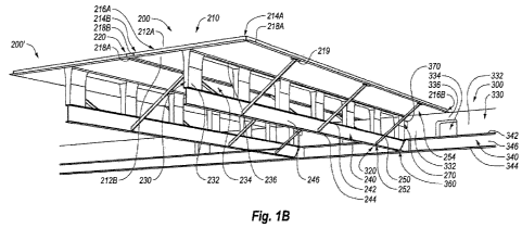
Figs. IA and lB illustrate a precast structural floor system 100 according to
one example. By way of introduction, the configuration of various aspects of
the
precast structural floor system will be introduced below, followed by a
discussion of
the formation of those components. Accordingly, the configuration of exemplary
composite floor panels will be discussed, followed by a discussion of the
configuration of exemplary composite girders. The structure of joints formed
between the composite floor panels will then be introduced as well as the
structure of
joints formed between composite floor panels and composite girders.
Thereafter, the
formation of a precast structural floor system will -be described which
includes a
discussion of an exemplary method of forming a precast structural floor
system, a
discussion of an exemplary method of forming a composite girder, a discussion
of an
exemplary method of forming a joint between adjacent composite floor panels
and
finally a discussion of forming a joint between a composite floor panel and a
composite girder.
As illustrated in Figs. IA and 1B, the example precast structural floor system
100 includes at least one composite floor panel, such as a composite floor
panel 200,
an adjacent composite floor panel 200', opposing composite floor panel 200",
and a
plurality of girders 300. Fig. 113 illustrates the composite floor panel 200
and the
adjacent composite floor panel 200' resting on the composite girder 300 in
which
intervening composite girder have been omitted for clarity. The labels
adjacent and
opposing are provided for ease of reference only. It will be appreciated that
the
composite floor panels within the precast structural floor system 100 can have
the
same or different configurations than discussed herein. For ease of reference,
similar
components in the composite floor panel 200 will be labeled with the same
reference
numbers as corresponding components in the adjacent composite floor panel
200'.
Accordingly, the composite floor panels 200, 200' are labeled for ease of
reference
only and the discussion of the composite floor panel 200 may be applicable to
the
CA 02798243 2012-11-02
WO 2011/139401 PCT/US2011/026751
7
composite floor panel 200' as well as other composite floor panels within the
precast
structural floor system 100.
As illustrated in Fig. 113, the example composite floor panel 200 may
generally include a concrete slab 210. A joint 220 maybe formed between
composite
floor panels 200, 200' and between the concrete slab 210 of the composite
floor
panels 200, 200' in particular. The joint 220 will be discussed in more detail
at an
appropriate point after a more complete description of the configuration of
the
example composite floor panel 200.
As illustrated in Fig. 1B, in addition to the concrete slab 210, the composite
floor panel 200 also includes a concrete stem wall 230, a steel panel beam
240, and a
plurality of braces 250. In at least one example, the concrete slab 210 maybe
formed
of a composite material, such as reinforced concrete, to thereby define upper
and
lower surfaces 212A, 212B, opposing sides 214A, 214B, and opposing ends 216A,
216B. One or more edge members 218A, 218B may also be embedded in the
concrete slab 210 to extend from the opposing sides 214A, 214B respectively.
As
shown in IB, each of the edge members 218A, 218B includes at least a generally
horizontal portion extending transversely from the concrete slab 210. Though
described as an edge member hereinafter, the edge members 218A, 218E may
include
only the horizontal portion shown. Further, as illustrated in Fig. 1B, each of
the
concrete slabs may also include weld plates 219 embedded in the concrete slab
210
adjacent the edge members 218A, 218B as desired. The example concrete slab 210
may be supported in any manner desired, one configuration of which will be
described in more detail below.
In the illustrated example, the concrete slab 210 may be supported by,
connected to, and/or integrally formed with the concrete stem wall 230. In
particular,
the stem wall 230 may extend downwardly and away from the lower surface 212B
of
the concrete slab 210. The stem wall 230 may include a plurality of stem
supports
232 with openings 234 (also referred to as blockouts) defined in the concrete
stein
wall 230 between the stem supports 232. The openings 234 may reduce the amount
of concrete utilized in the stem wall 230 relative to a continuous support,
which in
turn may reduce the dead load of the composite floor panel 200. In such a
configuration, the stem supports 232 provide the structure to transfer shear
loads
CA 02798243 2012-11-02
WO 2011/139401 PCT/US2011/026751
8
between the concrete slab 210 and the steel panel beam 240. Further, the
openings
234 may provide a convenient space to run HVAC ducts, piping and electrical
conduit.
In at least one example, the concrete stem wall 230 also includes a plurality
of
s ridges 236 that span the openings 234 between the stem supports 232. The
ridges 236
may be in contact with and/or integrally formed with the lower surface 212B of
the
concrete slab 210 as desired. In at least one example, the ridges 236 may have
a
thickness that is approximately 50 percent of the thickness of the concrete
slab 210.
Accordingly, the concrete stem wall 230 may vary in thickness along the
interface
to between the stem wall 230 and the concrete slab 210.
The concrete stem wall 230 is also connected to the steel panel beam 240. The
concrete stem wall. 230 may be connected to the steel panel beam 240 in any
suitable
manner, such as by welded studs and/or rebar. In the illustrated example, the
steel
panel beam 240 includes an I-Beam configuration. Accordingly, the steel panel
beam
15 240 may include an upper flange 242, a lower flange 244, and a web 246
between the
upper flange 242 and the lower flange 244. In the illustrated example, the
upper
flange 242 supports the stem supports 232.
The steel panel beam 240 may also serve as a base for the braces 250 to
provide additional support for the I-Beam and reduce vibration in the concrete
slab.
20 In the illustrated example, the braces 250 may include a lower end 252
secured to the
web 246 and/or the lower flange 244. An upper end 254 of the braces 250 may be
secured to the weld plates 219 embedded in the concrete slab 210. Such a
configuration can allow the steel panel beam 240 to support the concrete slab
210 by
way of the concrete stem wall 230 as well as the braces 250. The concrete slab
210,
25 the concrete stem wall 230, the openings 234, and the steel panel beam 240
can have
any desired dimensions.
In at least one example, the concrete slab 210 is about eight feet wide,
between
about five and 40 feet long, and about three inches thick. The concrete stem
wall 230
may be between, but not limited to, 12 and 36 inches in height. The openings
234 in
30 the concrete stem wall 230 may be located adjacent the concrete stem wall
230, and
may occupy the entire height of the concrete stem wall 230 as desired.
Further, in at
least one example, a 24 inch concrete stem wall 230 can be provided in which
the
CA 02798243 2012-11-02
WO 2011/139401 PCT/US2011/026751
9
openings 234 may be about 24 inches wide and 24 inches tall while the stem
supports
232 may be approximately twelve inches wide and be placed between the
openings.
In at least one example, the steel panel beam 240 may be about twelve inches
high
overall. Further, the upper flange 242 and/or the lower flange 244 may be
between
about four and eight inches wide.
In general, when a beam supported at both ends is loaded the top half of the
beam is under compression while the bottom half of the beam is under tension.
Concrete has relatively high compressive strength but relatively low tensile
strength,
while steel has high tensile and compressive strength. Steel beams, however,
may be
expensive relative to concrete. In the example composite floor panel 200, the
relative
position of the concrete slab 210 causes the concrete slab 210 to be under
compression while the relative position of the steel panel beam 240 may cause
the
steel panel beam 240 to be under tension. As a result, the configuration of
materials
of the composite floor panel 200 may utilize the best structural properties of
concrete
while optimizing the use of relatively expensive structural steel components.
Further, the configuration of the composite floor panel 200 allows them to be
quickly installed at a building site. As will be' discussed in more detail
below, the
composite floor panels 200 can be precast at a separate location as desired,
brought to
the building site, and lowered into place through the use of a crane. Once in
place, the
joint 220 may be formed between composite floor panels 200, 200' using binder
materials, such as grout, reinforcing materials; such as welded wire mesh,
anchors,
shear studs and/or other reinforcing materials and fastening procedures such
as
welding or bolting.
As shown in Fig. 113, a joint 320 may also be formed between the composite
floor panel 200 and the girder 300. The configuration of the composite girder
300
will first be introduced in more detail, followed by discussion of the joint
220
between adjacent composite floor panels 200, 200' and a subsequent discussion
of the
joint 320 between composite floor panel 200 and the girder 300.
With continuing reference to Fig. 1B, the example composite girder 300 may
generally include a concrete stem wall 330 and an I-Beam Configuration similar
to
that of the composite floor panel 200. In the illustrated example, the
concrete stem
wall 330 includes stem support 332 with openings 334 defined therein. Ridges
336
CA 02798243 2012-11-02
WO 2011/139401 PCT/US2011/026751
are formed above the openings 334. The ridges 336 may include a sufficient
amount
of continuous concrete (preferably between 33 and 50 percent of the height of
the
stein wall 330) so as to provide desired compression strength.
The concrete stem wall 330 can be coupled to or supported by the flange beam
5 340 in any desired manner. In the illustrated example, the flange beam 340
may
include an upper flange 342, a lower flange 344, and a web 346 that extends
between
the upper flange 342 and the lower flange 344. The upper flange 342 may be
configured to support the concrete stem wall 330.
A saddle 360 may be fastened to the flange beam 340 to provide support for
10 the steel panel beam 240. Accordingly, the composite girder 300 is
configured to
provide support for the composite floor panels 200, 200'. The configuration
and
interaction of the saddle 360 will be described in more detail below in
connection
with the description of the joint 320 formed between the composite girder 300
and the
composite floor panel 200 after a discussion of the joint 220 between adjacent
composite floor panels 200, 200'.
The configuration of the example joint 220 will now be discussed in more
detail. Fig. 2A illustrates a cross sectional view of adjacent composite floor
panels
200, 200' taken along section 2A-2A of Fig. IA. As illustrated in Fig. 2A, the
joint
220 includes the edge member-218B associated with the composite floor panel
200
and the edge member 218A associated with the adjacent composite floor panel
200'.
In particular, the edge members 218A, 218B include transverse portions 215A,
215B
and lateral portions 217A, 217B. The transverse portions 215A, 215B are shown
as
being generally horizontal while the lateral portions 217A, 217B are shown as
being
generally vertical. It will be appreciated that the transverse portions 21SA,
215B can
extend away from the sides 214A, 214B at any desired angle relative to the
lateral
portions 217A, 217B. It will also be appreciated that the lateral portions
217A, 217B
can be omitted as desired.
When a junction, such as a weld 290, is formed that connects the edge
members 218A, 21813, and the transverse portions 215A, 215B in particular, a
channel
is formed between the edge members 21 8A, 218B. In the illustrated example,
anchors
221 may be secured to the edge members 218A, 218B. The anchors 221 may also be
embedded within the concrete slab 210. In at least one example, the anchors
221 are
CA 02798243 2012-11-02
WO 2011/139401 PCT/US2011/026751
11
shear studs or other similar types of anchors. In the illustrated example, the
edge
members 218A, 218B are generally L-shaped to thereby define a generally
vertical
portion and a generally horizontal portion. It will be appreciated that other
configurations are possible, including an inverted T-configuration or any
other
configuration desired.
The joint 220 also includes binder material 222, such as high strength and/or
non-shrink grout. In the illustrated example, various reinforcements are
embedded in
the binder material 222. These reinforcements may include welded wire mesh 224
and/or reinforcements 226A, 226B.
to In at least one example, the reinforcement 226A is embedded in the side
214A
of the concrete slab 210 and extends through the edge member 218A into the
binder
material 222. Similarly, the reinforcement 226B may be anchored in the side
214B of
the concrete slab 210 and extend through the edge member 218B into the binder
material 222.
Fig. 2B illustrates a further cross sectional view of the joint 220 taken
along
section 2B-2B of Fig. 2A. As illustrated in Fig. 2B, the reinforcements 226A,
226B
may include first portions 227A, 227B and second portions 228A, 228B. The
first
portions 227A, 227B may be embedded in the composite floor panels 200' 200 and
extend into the binder material 222 as described above. As shown in Fig. 2B,
the
second portions 228A, 228B may be disposed at an angle relative to the first
portions
227A, 227B, thereby defining a bend therebetween.
In the illustrated example, the second portions 228A, 228B are generally
oriented parallel to the edge members 218B, 218A respectively. Further, the
second
portions 228A, 228B may be oriented to face each other. In addition, the first
portions 227A, 227B may extend sufficiently into the binder material 222 to
result in
overlap of the first portions 227A, 227B within the binder material 222. The
configuration of the reinforcements 226A, 226B can allow for rapid formation
of the
joint 220 as the composite floor panels 200, 200' (Fig. 1B) are lowered into
place on
the composite girder 300 (Fig. 1B). An exemplary configuration of the
interaction
between the example composite floor panels 200, 200' and the girder 300 will
first be
introduced with reference to Fig. 113. Thereafter, the example configuration
shown in
Fig. I B will be discussed in more detail with reference to Figs. 3A-3C.
CA 02798243 2012-11-02
WO 2011/139401 PCT/US2011/026751
12
As illustrated in Fig. I B, a joint 320 may be formed between the composite
floor panel 200 and the composite girder 300. The joint 320 may include
several
aspects. As illustrated in Fig. 1B, exemplary aspects of the joint 320 may
include a
saddle 360 secured to the flange beam 340, a girder joint plate 370 secured to
the
concrete stem wall 330, and a binder material 380 (Fig. 3C). By way of
introduction,
the joint 320 may be formed by placing the lower flange 244 of the steel panel
beam
240 in the saddle 360, fastening the lower flange 244 to the saddle 360,
fastening a
panel joint plate 270 to the girder joint plate 370, and applying the binder
material 380
(Fig. 3C), which can allow the joint 320 to be formed rapidly.
to Fig. 3A illustrates a partial cross-sectional view of the joint 320 taken
along
section 3A-3A of Fig. IA. As illustrated in Figs. 3A and 3B, the saddle 360
generally
includes opposing side plates 362A, 362B and a bottom plate 364. The bottom
plate
364 may be fastened to and extend between the opposing side plates 362A, 362B
to
define a recess configured to receive at least a portion of the steel panel
beam 240.
As particularly shown in Fig. 3B, the lower flange 244 can be placed on the
lower plate 364 of the saddle 360. The lower flange 244 can also be secured in
place
relative to the saddle 360. In at least one example, the lower flange 244 can
be
secured to the lower plate 364 by fasteners 366 that pass through both the
lower
flange 244 and the lower plate 364. Accordingly, one aspect of the joint 320
may
include the securing of the steel panel beam 240 in place within the saddle
360.
Fig. 3C illustrates a partial cross-sectional view of the joint 320 taken
along
section 3C-3C of Fig. 3A. As illustrated in Fig. 3C, another aspect of the
joint 320
includes securing the girder joint plate 370 to the panel joint plate 270. The
example
panel joint plate 270 may be secured to anchors 272, such as shear studs or
other
types of anchors. The anchors 272 may be embedded within the concrete stem
wall
230, thereby securing the panel joint plate 270 to the composite floor panel
200.
Similarly, the example girder joint plate 370 may be secured to anchors 372
embedded within the concrete stein wall 330, thereby securing the girder joint
plate
370 to the girder 300. In at least one example, the anchors 372 are shear
studs. The
panel joint plate 270 can be secured to the girder joint plate 370 in any
suitable
manner, such as by welding, fasteners, and/or in any other manner.
CA 02798243 2012-11-02
WO 2011/139401 PCT/US2011/026751
13
Another aspect of the joint 320 is also shown in Fig. 3C. In particular, when
the composite floor panel 200 is positioned on the composite girder 300, a
recess 352
is defined between the composite floor panel 200 and the composite girder 300.
Further, the second end 216B may include an edge angle 280B. The edge angle
280B
may be secured to one or more anchors 282, 283. In particular, anchor 282 may
be
secured to the edge angle 280B and be embedded in the end 216B while anchor
283
may be secured to the edge angle 280B and extend into the recess 352. The
anchors
282, 283 may be any desired type of anchor, such as shear studs. The opposing
edge
216A (Fig. 113) may also be similarly configured.
Reinforcements 382 may also be embedded within the concrete stem wall 330.
The reinforcements 382 may extend into the recess 352. As a result, when the
binder
material 380 is placed in the recess 352, the anchors 283 as well as the
reinforcements
382 may be embedded within the binder material 380. Further, additional
reinforcements, such as welded wire mesh 384, may also be embedded within the
binder material 380.
In at least one example, the binder material 380 may include a grout material,
such as a non-shrink grout material. Accordingly, the joint 320 may be formed
with
several aspects that secure the composite floor panel 200 to the composite
girder 300.
The joint 320 between the composite floor panel 200 and the composite girder
300 as
well as the joint 220 (Fig. IA) between the composite floor panels 200, 200'
can be
rapidly formed. Exemplary methods for forming the composite floor panel 200,
the
composite girder 300, the joint 220, and the joint 320 will now be discussed.
Fig. 4A illustrates various steps of an example method of forming a composite
floor panel. As illustrated in Fig. 4A, the method can include cutting the
steel panel
beam 240 to an appropriate length per shop drawings approved by the engineer
of
record. Holes 247 for securing the steel panel beam 240 to the saddle 360
(Figs. 3A-
3B) may then be drilled into the lower flange 244 of the steel panel beam 240.
The steel panel beam 240 may then be placed upright so as to rest on the lower
flange 244. Nelson studs 400 or similar connectors are then welded to the top
side of
the upper flange 242. Spacing of the Nelson studs 400 is per approved shop
drawings
at intervals less than or equal to the maximum spacing allowed by prevailing
building
codes. Vertical L-shaped reinforcing bars 410 may then be welded into place
adjacent
CA 02798243 2012-11-02
WO 2011/139401 PCT/US2011/026751
14
to the Nelson studs 400 which were previously welded to the upper flange 242
of the
beam. The vertical reinforcing bars 410 may project upward from the upper
flange
242 and then turn 90 degrees to thereby define short legs 412 and long legs
414. In
such a configuration, the short legs 412 of the L-shaped reinforcing bars 410
run
horizontally and perpendicular to a longitudinal axis 248 of the steel panel
beam 240.
The vertical reinforcing bars 410 are spaced according to the shop drawings
approved
by the engineer of record, typically with one vertical reinforcing bar 410 per
every
Nelson stud 400.
Lifting loops 420 made from reinforcing bar or other similar steel bar which
to have been bent into u-shapes may also be secured to the upper flange 242 of
the steel
panel beam 240 between the vertical reinforcing bars 410 where concrete will
be
poured to surround the lifting loops 420 and vertical reinforcing bars 410,
leaving the
tops of the lifting loops uncovered by concrete for lifting with a crane. The
length of
the lifting loops 420 may be approximately .25" less than the distance from
the top
side of the upper flange 242 to the top surface of the finished concrete slab
210 (Fig.
1B). Lifting loops 420 may be spaced at intervals determined by the overall
length of
the composite floor panel 200. In at least one example, three lifting loops
420 are
used per finished composite floor panel 200 (Fig. 1B).
The assembled steel panel beam 240, with the vertical L-shaped reinforcing
bar 410 and the lifting loops 420 secured thereto, is then moved to a floor-
mounted jig
(not shown) to hold the components steady while horizontal slab reinforcements
430,
440 are secured in place. In particular, the reinforcing bars 430 may be
oriented
parallel to the longitudinal axis 248 of the steel panel beam 240. The
reinforcing bars
430 may be tied into place using standard tie wire to the horizontal legs 412
of the L-
shaped reinforcing bars 410 or in any other suitable manner.
Reinforcing bars 440, which may be oriented perpendicular to the longitudinal
axis 248 of the steel panel beam 240, may then be tied to the previously
installed
reinforcing bars 430. In at least one example, the reinforcing bars 430, 440
may be
cut to a length about two inches shorter than the overall length or width of
final
concrete slab 210 (Fig. I B) in which they are to be cast. Further, the
reinforcing bars
430, 440 may be tied with tie wire at all intersections as desired. Additional
CA 02798243 2012-11-02
WO 2011/139401 PCT/US2011/026751
reinforcing bars 430, 440 may then be tied to the other reinforcements as
desired to
form a desired grid.
Blockout forms 450 may be secured to the upper flange 242 at any desired
point during the formation process. In at least one example, the blockout
forms 450
5 may be formed of metallic material secured to the steel panel beam 240. In
particular, the blockout forms 450 may be formed of steel plates that are bent
to a
desired shape. The blockout forms 450 may be secured to the steel panel beam
240 in
any desired manner, such as by welding, magnets, fasteners such as bolt,
and/or clips.
In another example, the blockout forms 450 may be made using a variety of
1o materials, including but not limited to, styrene foam, rubber, wood and
steel. In the
case that the blockout forms 450 are formed of styrene foam blocks, the
blockout
forms 450 may be secured to the steel panel beam 240 by use of an adhesive,
such as
tape or glue. The blockout forms 450 may also be coated in form release oil or
silicone to prevent the blockout forms 450 from bonding to the concrete of the
15 concrete stem wall 230 (Fig. 1B) that is poured around it.
The resulting assembly may then be placed into a form 460, as illustrated in
Fig. 4B. Fig. 4B illustrates a cross-sectional, view of the support surface 40
and the
form 460 and an end view of the components within the form 460. It will be
appreciated that the form 460 may be closed on either end.
The form 460 may be sprayed with form release oil prior to placing the
components in the form 460 as desired. In at least one example, forms 460 may
be
formed of steel. The structure of the forms 460 can vary in length and width
as well as
construction so long as the inside shape of the form is the correct profile
for the
finished concrete portion of the composite floor panel 200 (Fig. 1B). The form
460
may be of sufficient strength to allow for numerous repetitive uses while
maintaining
the correct shape and configuration.
The edge members 218A, 218B, weld plates 219, reinforcements 227A, 227B,
anchors 221, and other desired reinforcements are positioned in the form 460
and
secured by tie wire or small bolts and held in position until the concrete has
cured
sufficiently. Though not shown, the other edge angles 280A, 280B,
reinforcements
272, and anchors 282, 283 as well as the weld plate shown in Fig. 3C may also
be
CA 02798243 2012-11-02
WO 2011/139401 PCT/US2011/026751
16
placed into the form 460 and tied in place until the concrete has cured
sufficiently.
Welded wire mesh 435 may also be secured in place as desired.
Rebar chairs (not shown) may be placed under the reinforcing bars 430, 440 to
maintain a desired separation between the lower surface 212B (Fig. 1B) of the
concrete slab 210 and the underside of the reinforcing bars 430, 440. Rebar
chairs
may be spaced as desired, as determined by visual inspection once the beam
assembly
has been set in place and all the components described above have been tied
securely
to the reinforcing bars 430, 440. While one method of providing reinforcements
has
been described, it will be appreciated that any number of reinforcements
assembled in
any number of manners may also be provided.
Concrete (not shown) is placed in the forms in a manner to ensure that all
reinforcing bars 430, 440 are sufficiently covered to thereby form the
concrete slab
210 and concrete stem wall 230 (both seen in Fig. 1B). The upper surface of
the
concrete slab 210 may then be finished to industry standards for concrete
floors.
Thereafter, the concrete can be cured by any acceptable method as defined by
precast
concrete industry standards. Once the concrete has cured sufficiently the
panel 200
(Fig. 113) is lifted out of the forms by the lifting loops 420 attached to the
steel panel
beam 240. The panel 200 may then be set on a flat, level surface and held
level by
blocking, stands or other means acceptable to hold it level without putting
excessive
stresses on any one point in the panel 200.
The braces 250 shown in Fig. lB may then he secured to the weld plates 219
and the upper flange 242 of the steel panel beam 240, such as by welding. The
blockout forms 450 (Fig. 4A) may then be removed to thereby form the opening
234
previously discussed. Bolts or tie wire which were used to secure the
components in
place before the concrete was formed and which are projecting from the
concrete slab
210 may be cut off flush with the lower surface 212B of the concrete slab 210.
Figs. 5A and 5B illustrate an exemplary method of forming a composite
girder. As illustrated in Fig. 5A, the method may include cutting the flange
beam 340
to an appropriate length per shop drawings approved by the engineer of record.
Holes
390 used for connecting the flange beam 340 to columns (not shown) are then
drilled
into each end of the flange beam 340.
CA 02798243 2012-11-02
WO 2011/139401 PCT/US2011/026751
17
The flange beam 340 may then be oriented to rest on the lower flange 344.
Nelson studs 500 or similar connectors may then be secured to an upper surface
of the
upper flange 342. Spacing of the Nelson studs 500 is per approved shop
drawings at
intervals less than or equal to the maximum spacing allowed by prevailing
building
codes. Vertical L-shaped reinforcing bars 510 may then secured to the upper
flange
342 into place. In at least one example, the L-shaped reinforcing bars 510 are
positioned adjacent to Nelson studs 500 which were previously secured to the
upper
flange 342 of the flange beam 340.
In at least one example, the L-shaped reinforcing bar 510 projects upward
to from the upper flange 342 of the composite girder 300 and then turns ninety
degrees
to project horizontally and perpendicular to the longitudinal axis 348 of the
flange
beam 340. Asa result, the L-shaped reinforcing bars 510 include a short leg
512 and
a long leg 514. The L-shaped reinforcing bars 510 may be spaced according to
the
shop drawings approved by the engineer of record, typically with one L-shaped
reinforcing bar 510 per everyNelson stud 500.
Lifting loops 520, such as reinforcing bar which has been bent into a u-shape,
are also secured to the upper flange 342 of the flange beam 340. The length of
the
lifting loops 520 may be approximately .25" less than the distance from an
upper
surface of the upper flange 342 of the beam to a top surface of the completed
concrete
stem wall 330 (Fig. 1B). The lifting loops 520 may be spaced at desired
intervals
determined by the overall length of the composite girder 300 (Fig. IB). In at
least one
example, two or more lifting loops 520 may be used on any single composite
girder
300 (Fig. 1B).
The flange beam 340 with the lifting loops 520 and the L-shaped reinforcing
bars 510, is then moved to a floor-mounted jig (not shown) to hold it steady.
Reinforcing bars 530, which may be oriented generally parallel to the
longitudinal
axis 348 of the flange beam 340, may be tied to the short legs 512 of the L-
shaped
reinforcing bars 510. Reinforcing bars 540, which may be oriented generally
perpendicular to the longitudinal axis 348 of the flange beam 340, may then be
positioned on the reinforcing bars 530 and tied into place. In at least one
example, the
reinforcing bars 530 may be tied in place using 16 gauge tie wire.
CA 02798243 2012-11-02
WO 2011/139401 PCT/US2011/026751
18
Blockout forms 550 may be secured to the upper flange 342 at any desired
point during the formation process. In at least one example, the blockout
forms 550
may be formed of metallic material secured to the flange beam 340. In
particular, the
blockout forms 550 may be formed of steel plates that are bent to a desired
shape.
The blockout forms 550 may be secured to the flange beam 340 in any desired
manner, such as by welding, magnets, fasteners such as bolts, and/or clips.
In another example, the blockout forms 550 may be formed of a foam material
that are secured to the upper flange 342 of the flange beam 340, such as by
adhesives
such as glue and/or tape. The flange beam 340 with the reinforcements
described
above are then placed into a form 560 as shown in Fig. 5B. Though not shown in
Fig.
5B, the girder joint plate 370 and the anchor 372, as well as anchors 272
shown in
Fig. 3C may also be placed in the forms and maintained in desired positions in
any
suitable manner.
Concrete is placed in the form 560 in a manner to ensure that all the
reinforcing bars 510, 530, 540 are sufficiently covered, typically leaving the
tops of
the lifting loops 520 not covered in concrete. One or more of the surfaces may
then be
finished to industry standards for concrete floors. The resulting girder may
be cured
by industry accepted methods. Once the concrete has cured sufficiently the
composite
girder 300 is lifted out of the form 560 by the lifting loops 520.
The forms 560 may have any configuration. In at least one example, the
form560 are formed from a metallic material, such as steel. Further, the
structure of
the form 560 can have any inside shape to provide a desired profile for the
finished
composite girder 300. The forms may also be of sufficient strength to allow
for
numerous repetitive uses while maintaining the correct shape and
configuration.
The saddles 360 described above (Fig. 113) may be secured to the lower flange
344 of the flange beam 340 at any desired point during or after the formation
of the
composite girder 300. As illustrated in Fig. 3B, the saddle 360 may be secured
to the
flange beam 340. In the example shown in Fig. 3A, the opposing side plates
362A,
362B may he secured to the lower flange 344 and/or the web 346, such as by
welding
and/or fastening. The lower plate 364 of the saddle 360 may be secured to the
opposing side plates 362A, 362B and/or the lower flange 344, such as by
welding
and/or fastening. A stiffener plate 368 may be secured to an opposing side of
the
CA 02798243 2012-11-02
WO 2011/139401 PCT/US2011/026751
19
flange beam 340 as desired. In the illustrated example, the stiffener plate
368 is
secured to the lower flange 344, the web 346, and the upper flange 342 (not
shown in
Fig. 3B).
Once the composite girders 300 and the composite floor panels are completed,
the precast structural floor system 100 as shown in Fig. 1A may be assembled.
In at
least one example method, the composite girders 300 may be positioned by a
crane by
way of cables or straps attached to the lifting loops 520 (Fig. 5A). In such
an
example, the crane may lift the composite girder 300 into place relative to a
column
110. The composite girder 300 can then be secured in place. In particular, the
flange
to beam 340 can be fastened to the column 110 through the use of fasteners
passed
through the column holes 390 (Fig. 5A). Welded connections can be specified by
the
engineer of record as desired.
Once the composite girders 300 are in place, the composite floor panels 200,
200', 200" may be installed. In at least one example, the composite floor
panel 200
may be positioned by a crane via a cable secured to the lifting loops 420
(Fig. 4A).
In particular, as shown in Fig. 3C, the composite floor panel 200 may be set
into place
such that the steel flange beam 240 is positioned within the saddle 360, the
edge
angles 280B, 280A (not shown in Fig. 3C) are attached to the concrete stem
wall 330,
and the panel joint plates 270 are proximate the girder joint plates 370. Any
number
of composite floor panels 200 can be placed on the composite girder 300. The
joints
220 may then be formed between the composite panels 200, 200' and the joints
320
may be formed between the composite panels 200, 200" and the composite girder
300. The formation of the joints 220 between the composite floor panels 200,
200'
will now be discussed.
As illustrated in Fig. 2A, the joint 220 may be formed by positioning the edge
members 218A, 218B in proximity with one another and then securing the edge
members 218A, 218B together. In the illustrated example, a weld 290 may be
used,
but is not required to join the edge members 218A, 218B. Once the edge members
218A, 218B are secured together, the binder material 222 may be added and the
wire
mesh 224 embedded in the binder material 222. The binder material 222 may then
be
cured to provide the resulting joint 220 shown in Fig. 2A. Accordingly, the
joint 220
CA 02798243 2012-11-02
WO 2011/139401 PCT/US2011/026751
may be formed rapidly once composite panels 200, 200' are in place using the
preformed composite floor panels 200.
Similarly, the joint 320 between the composite floor panel 200 and the
composite girder 300 may also be formed rapidly. In particular, once the
composite
5 floor panel 200 is positioned relative to the composite girder 300 as
described above
and as shown in Fig. 3C, the joint 320 may be formed by securing the lower
flange
244 of the steel panel beam 240 to the saddle 360, securing the panel joint
plate 270 to
the girder joint plate 370, and placing the binder material 380 on top of the
concrete
stem wall 330 and the edge angle 280B to cover the anchors 282, 283 and then
10 placing the wire mesh 384 within the binder material 380. The resulting
joint 320 can
then be cured and finished as desired. Accordingly, the joint 320 may be
rapidly
formed once the composite panel 200 is in place.
While example joints 220 between composite floor panels 200 and between
composite floor panels 200 and composite girder 300 have been described, it
will be
15 appreciated that other configurations are possible. For example, Figs. 6A-
6D
illustrate additional exemplary joints 610, 620, 630, and 640 respectively.
For ease of
reference, the following elements are similar to those described above with
reference
to Figs. 1A-5B.
For example, in Fig. 6A the joint 610 includes a junction formed by a
20 continuous pour stop 612 that is placed between the edge members 218A,
218B. Fig.
6B illustrates the joint 620 including edge members 218A, 218B that include
shear
studs 622, 624 secured to the edge members 218A, 218B. In particular, shear
studs
622 extend into the concrete slab 210 while shear studs 624 extend into the
binder
material 222. Fig. 6C illustrates that the joint 630 may include a junction
formed by
high-strength thru-bolts 632 and square washers 634 that secure the edge
members
218A, 218B. As illustrated in Fig. 6D, integral shear studs 622, 624 may also
be used
in conjunction with the thru-bolts 632 and square washer 634 as desired.
Further, it
will be appreciated that any number of reinforcements and fastening methods
may be
used in any number of combinations in addition to those described above.
In addition, a joint 710 may be between the composite floor panel 200, the
composite girder 300, and an opposing composite floor panel 200" in addition
to
CA 02798243 2012-11-02
WO 2011/139401 PCT/US2011/026751
21
between a composite floor panel 200 and the composite girder 300 as previously
described, as shown in Fig. 7.
Further, Figs. 8A-8C illustrate an alternative embodiment of a composite floor
panel 800. In particular, Fig. 8A is a bottom plan view of the composite floor
panel
800. The composite floor panel 800 can include a frame assembly 805 that is
coupled
to and supports a concrete portion 810. The configuration of the frame
assembly 805
will first be introduced with reference to the concrete portion 810 generally,
after
which the configuration of the concrete portion 810 will be discussed in more
detail.
Thereafter, the structural relationships between the frame assembly 805 and
the
concrete portion 810 will be discussed in more detail.
As illustrated in Fig. 8A, the frame assembly 805 includes a first lateral set
of
support members 815, a second lateral set of support members 820, and a base
plate
825 that is offset from the concrete portion 810. Each of the first and second
sets of
lateral support members 815, 820 can have a first end coupled to the concrete
portion
t5 810 and a second end coupled to the base plate 825. The base plate 825
could also be
a steel tension member, steel bottom cord or steel bottom flange. The first
set of
lateral support members 815 can include a plurality of supports, such as
supports
830A-830H that extend from the concrete portion 810 to the base plate 825.
In at least one example, the supports 830A-830H are oriented such that the
supports 830A-830H are positioned in a common plane as shown more clearly in
Fig.
SC. For example, Fig. 8C illustrates at least a portion of the first set of
lateral support
members 815 being aligned in at least one common plane with support 830G shown
and supports 830A-830F positioned behind support 830G and thus hidden from
view
in Fig. 8C. Further, the supports 830A-830H can be secured to the base plate
825 in
any suitable manner at any number of desired locations. In at least one
example, the
supports 830A-830H are secured to the base plate 825 in such a manner that
connections between the supports 830A-830H and the base plate 825 lie in a
line.
As also shown in Fig. 8A, the second set of lateral support members 820 can
include a plurality of supports, such as supports 835A-835H. In the
illustrated
example, the supports 835A-835H can be oriented and positioned such that the
supports 830A-830H lie in a common plane that is different than the common
plane
with respect to supports 830A-8301-1, as shown more clearly in Fig. 8C. For
example,
CA 02798243 2012-11-02
WO 2011/139401 PCT/US2011/026751
22
Fig. 8C illustrates at least a portion of the second set of lateral support
members 820
being aligned in at least one plane with support 835G shown and supports 835A-
835F
positioned behind support 835G and thus hidden from view in Fig. 8C. In the
illustrated example, the supports 835A-835H lie in a plane that is oriented at
an angle
to the plane in which supports 830A-830H lie.
The supports 835A-835H can be secured to the base plate 825 in any suitable
manner at any number of desired locations. In at least one example, the
supports
835A-835H are secured to the base plate 825 in such a manner that connections
of the
supports 835A-835H and the base plate 825 lie in a line on the base plate 825.
In at
least one example, the connections between the base plate 825 and the supports
835A-
835H and the connections between the base plate 825 and the supports 830A-830H
all
lie in a common plane on the base plate 825. It will be appreciated that other
configurations are also possible.
In addition, one or more of the supports 830A-830H of the first set of lateral
support members 815 can be joined at substantially the same location on the
base
plate 825 as one or more of the supports 835A-835H of the second set of
lateral
support members 820. In particular, as shown in Fig. 8A, supports 830A and
835A
can be secured to the base plate 825 at a common location. Similarly, supports
830B,
830C, 835B, and 835C can also be secured to the base plate 825 at another
common
location. Supports 830D, 830E, 835D, and 835E can also be secured to the base
plate
825 at yet another common location, supports 830F, 830G, 835F, and 835G can be
secured to the base plate 825 at yet another common location, and supports
830H and
835H can also be secured to the base plate 825 at still another common
location.
As shown in Fig. 8A, the configuration and relative orientation of first and
seconds sets of lateral support members 815, 820 can cause the frame assembly
805 to
form a plurality of trusses with the concrete portion 810. For example, a
group or
web of trusses can be formed that include a truss formed by supports 830B and
830C
and the concrete portion 810, another truss by supports 830C,835C and the
concrete
portion 810, yet another truss between supports 835C, 835B and the concrete
portion
810, and still yet another truss between supports 835B and 830B. Similar
groups or
webs of trusses can also be formed with supports 830D, 830E, 835D, and 835E as
well as with 830F, 830G, 835F, and 835G. Accordingly, supports 830B-830G
CA 02798243 2012-11-02
WO 2011/139401 PCT/US2011/026751
23
cooperate with supports 835B-835G to form truss webs on an interior portion of
the
composite floor panel 800 relative to end edges 840, 845 of the concrete
portion 810.
According to one embodiment of the invention, the first and second sets of
lateral support members 815, 820 can be secured to the concrete portion 810 so
as to
have substantially similar distances between first ends of adjacent supports.
For
example, in one embodiment, the distance between the first end of support 830A
and
the first end of support 835A is substantially equal to the distance between
the first
end of support 830A and the first end of support 830B, which can be
substantially
equal to the distance between the first end of support 835A and the first end
of
to support 835B, which can be substantially the same distance between the
first end of
support 830B and the first end of support 830C, and so forth. In another
embodiment,
the distance between the first end of support 830B and the first end of
support 830C is
substantially equal to the distance between the first end of support 835B and
the first
end of support 835C.
As also shown in Fig. 8A, supports 830A, 835A can extend toward the end
edge 840 while supports 830H, 835H extend toward the end edge 845. In the
illustrated example, a girder connection plate 846 is provided which can be
secured to
concrete portion 810 and to the first end of support 830A, and another girder
connection plate 847 is provided which can be secured to concrete portion 810
and to
the first end of support 835A. Similarly, another girder connection plate 848
is
provided which can be secured to concrete portion 810 and to the first end of
support
830H, and yet another girder connection plate 849 is provided which can be
secured
to concrete portion 810 and to the first end of support 835H.
In at least one example, the supports 830A-830H, 835A-835H, can be formed
of a high-strength material, such as steel. For example, the supports 830A-
830H,
835A-835H, can be formed from rolled steel angle members and/or heavy gauge
bent
shapes. The girder connection plates 846-849 can also be formed of a high-
strength
material, such as steel, including rolled steel angle members and/or heavy
gauge bent
shapes.
In at least one example, the base plate 825 can be a steel plate with a
thickness
of between about 3/8 inch and about 5/8 inch or more. Further, as shown in
Fig. 8A,
the base plate 825 can be shaped such that the base plate 825 is relatively
narrower at
CA 02798243 2012-11-02
WO 2011/139401 PCT/US2011/026751
24
end portions 825A, 825B and wider near a central portion 825C of the base
plate 825.
For example, the base plate 825 can have center width of between about five
inches
and about eight inches and end widths of between about four inches and about
six
inches. Such a configuration can provide relatively more material, such as
steel, near
the center of the composite floor panel 800 thereby increasing the section
modulus
and the moment of inertia at the center of the span where the greater capacity
may be
desirable, which in turn can allow for better performance for a given amount
of
material. In other examples, the base plate 825 can have a constant width or
can have
a relatively narrower central portion 825C than at end portions 825A, 825B.
to Accordingly, the base plate 825 can be configured as desired to provide a
base for the
supports 830A-830H, 835A-835H. The base plate 825 can also provide a base for
additional supports.
Fig. 8B illustrates a cross sectional view of the composite floor panel 800
taken along section 8B-8B of Fig. 8A. As shown in Fig. 8B, the frame assembly
805
also includes end supports 850A, 850B coupled at a first end to the concrete
portion
810 and coupled at a second end to the base plate 825. In the example shown in
Fig.
813, the end supports 850A, 850B can extend from the concrete portion 810 to
the
base plate 825. According to one embodiment, end support 850A can be
positioned
relative to base plate 825 and concrete portion 810 such that support 835A is
positioned directly behind end support 850A as illustrated. In this
orientation, end
support 850A and support 835A, and likewise support 830A, can all share a
common
plane. Similarly, end support 850B and supports 83511, 830H can be aligned and
thus
share a common plane, as partially illustrated in Fig. 8B.
As shown in the illustrated embodiment, a girder connection plate 851 is
provided which can be secured to end support 850A, and another girder
connection
plate 852 is provided which can be secured to a similar end support 850B
positioned
on the opposing end of the composite floor panel 800. In the illustrated
example, the
girder connection plate 851 is positioned beneath the end edge 840 of the
concrete
portion while girder connection 852 is positioned beneath the opposing end
edge 845
of the concrete portion 810. Such configuration can allow the girder
connection
plates 851, 852 to thereby support opposing ends of the concrete portion 810.
Referring again briefly to Fig. 8A, girder connection plates 846-849 can be
secured to
CA 02798243 2012-11-02
WO 2011/139401 PCT/US2011/026751
concrete portion 810 in a similar manner such that the girder connection
plates 846-
849 are positioned beneath the corresponding end edges 840, 845.
Support members 815 can be positioned in a corresponding manner with the
position of support members 820, such that adjacent supports can share a
common
s plane. For example, Fig. 8B illustrates support members 820 being connected
to base
plate 825 and extending toward concrete portion 810 at an angle with respect
to base
plate 825. Support members 820 can have a corresponding angle with respect to
base
plate 825. According to one embodiment, support 830A and support 835A have a
substantially similar angle from the base plate 825 such that support 830A and
1o support 835A share a common plane. Similarly, end support 850A can have a
substantially similar angle from the base plate 825 as support 830A and
support 835A,
thus rendering supports 830A, 835A and end support 850A to be substantially
aligned
in a common plane. Similarly, support 830B can share a common plane with
support
835B as a result of a substantially similar angle between support 830B and
base plate
15 825 and between support 835B and base plate 825. Likewise, supports 830C,
835C
can share a common plane, supports 830D, 835D can share a common plane,
supports
830E, 835E can share a common plane, supports 830F, 835F can share a common
plane, supports 830G, 835G can share a common plane, and supports 830H, 835H
and
end support 850B can share a common plane, each resulting from a similar angle
20 between corresponding supports and the base plate 825.
Fig. 8C is a cross sectional view of the composite floor panel 800 taken along
section 8C-8C of Fig. 8A and illustrates the structure of the concrete portion
810 in
more detail. As illustrated in Fig. 8C, the concrete portion 810 generally
includes a
concrete slab 860, a first beam portion 865A, and a second beam portion 865B.
The
25 concrete slab 860 shown includes a generally planar top surface 867, a
first lateral
portion 870A and a second lateral portion 870B. In the illustrated example, an
edge
angle 880A is embedded in the first lateral portion 870A while another edge
angle
880B is embedded in the second lateral portion 870B.
As shown in Fig. 8C, the first beam portion 865A and the second beam portion
865B extend downwardly and away from the concrete slab 860. In particular, the
first beam portion 865A and the second beam portion 865B can be integrally
formed
with the concrete slab 860. Further, the first beam portion 865A and the
second beam
CA 02798243 2012-11-02
WO 2011/139401 PCT/US2011/026751
26
portion 865B can extend longitudinally along the length of the composite floor
panel
800. In at least one example, a center of the first beam portion 865A and a
center of
the second beam portion 865B can be separated by a distance of between about
four
feet and about five feet or more, but preferably the spacing between the first
beam
portion 865A and the second beam portion 865B is approximately five feet. The
first
and second beam portions 865A, 865B can have a width of between about four
inches
and about eight inches and a height of between about six inches and about
eight
inches. Accordingly, the first beam portion 865A and the second beam portion
865B
can be thicker than the rest of the concrete portion 810, including the
concrete slab
860. The increased thickness of the first and second beam portions 865A, 865B
can
allow the first and second beam portions 865A, 865B to provide additional
support for
the remainder of the concrete portion 810. In at least one example, the frame
assembly 805 is coupled to the concrete portion 810 by way of the first and
second
beam portions 865A, 865B, as will be described in more detail below.
Referring again to Fig. 8A, the first set of lateral support members 815 is
coupled to the concrete portion 810 by way of the first beam portion 865A and
the
second set of lateral support members 820 is coupled to the concrete portion
810 by
way of the second beam portion 865B. In particular, supports 830A-830H can
couple
to the first beam portion 865A and supports 835A-835H can couple to the second
beam portion 865B. According to one embodiment, reinforcements, such as
plates,
rebar, anchors, and/or any other desired reinforcements can be placed within
the
concrete portion 810 to anchor the supports 830A-830H, 835A-835H, 850A-850B to
the concrete portion 810 (collectively shown in Figs. 8A-8C). As also shown
collectively in Figs. 8A-8C, supports 830A-830H, 835A-835H, 850A-850B can
space
the base plate 825 at a distance of between about four and five feet from a
bottom
surface 869 (best seen in Fig. 8C) of the concrete slab 860. As will be
appreciated,
supports 815, 820 can be modified to offset base plate 825 from concrete slab
860 a
desired distance.
As shown particularly in Figs. 8B and SC, the composite floor panel 800 can
3o also include a layer of material 895 to facilitate, among other things,
formation of the
concrete portion 810 as well as provide an insulation layer to dampen sound
and/or
reduce unwanted transfer of heat. In one embodiment, the layer of material 895
is a
CA 02798243 2012-11-02
WO 2011/139401 PCT/US2011/026751
27
foam insulation form. Foam insulation form 895 was omitted from Fig. 8A to
focus
on the configuration of the frame assembly 805. It will be appreciated that
the foam
insulation form 895 can be an integral part of the composite floor panel 800
that abuts
the concrete portion 810 shown in Fig. 8A.
In at least one example, the foam insulation form 895 can have a shape that is
the negative or inverse of the concrete portion 810, including any desired
part of the
concrete slab 860 and/or the first and second beam portions 865A, 865B. Such a
configuration can also provide a layer of floor insulation for both sound and
temperature. Further, the foam insulation form 895 can also be used to house
and
otherwise preinstall a radiant floor heating and cooling system as desired.
The foam
insulation form 895 can be provided separately or can be used during the
formation of
the concrete slab 860 and the first and second beam portions 865A, 865B. One
exemplary method of forming the composite floor panel 800 will now be
discussed in
more detail. Though various steps will be described in an exemplary order, it
will be
appreciated that the steps described below can be performed in a different
order and
some steps can be omitted entirely as appropriate or desired. Further, steps
can be
combined and/or split as desired.
Referring collectively to Figs. 8A-8C, forming the composite floor panel 800
can include securing the second ends of supports 815, 820 and end supports
850A,
850B to the base plate 825, forming a concrete portion 810 and securing the
first ends
of supports 815, 820 and end supports 850A, 850B to the concrete portion 810.
Supports 815, 820 and end supports 850A, 850B can be secured to base plate 825
by
various securing methods, such as welding or through a traditional fastener
such as a
threaded coupling (i.e. bolt).
After supports 815, 820 and end supports 850A, 850B are secured to base
plate 825, the foam insulation form 895 is then positioned relative to the
supports
830A-830H, 835A-835H, 850A, 850B. The foam insulation form 895 can be
supported in any suitable manner to maintain the foam insulation form 895 at a
desired position and orientation relative to the base plate 825 and the
supports 830A-
830H, 835A-835H, 850A-850B.
Though not shown, reinforcements such as nelson studs, reinforcing rebar,
shear studs, and any other reinforcement and/or intermediate supports can be
CA 02798243 2012-11-02
WO 2011/139401 PCT/US2011/026751
28
positioned as desired relative to the foam insulation form 895. The
reinforcements
and/or intermediate members can be secured to each other and maintained in
their
position relative to the foam insulation form 895 in any manner desired,
including
through the use of wire, rcbar chairs, and/or any other components as desired.
In at
least one example, lifting loops can also be provided as desired. Such
reinforcements
can also be used to tie the first ends of supports 815, 820, 850A, 850B
together or to
simply position the first ends of supports 815, 820, 850A, 850B in appropriate
positions with respect to each other.
In one embodiment, securing the first ends of the supports 815, 820, 850A,
850B to the concrete portion 810 can include forming a beam around at least a
portion
of the first end of a support. In an alternative embodiment, securing the
first end of a
support to the concrete portion can include securing at least a portion of the
first end
of the support to a reinforcement member, such as rebar or a metal plate or
some other
type of fixture designed to be enclosed within the beam. In this manner, the
support is
coupled or otherwise connected to the beam and ultimately to the concrete
portion.
Thereafter, the first and second beam portions 865A, 865B and at least a
portion of the concrete slab 860 can be formed by pouring concrete into the
foam
insulation form 895. Thereafter, the concrete can be cured and the composite
floor
panel 800 can be ready for assembly with other composite floor panels 200 to
form a
precast structural floor system 900 (Figs. 9A-9B), as will be described in
more detail
below.
Figs. 9A and 9B illustrate a precast structural floor system 900. In
particular,
Fig. 9A illustrates a top view of a precast structural floor system 900 while
Fig. 9B
illustrates a cross sectional view of the pre-cast structural floor system
taken along
section 9B-9B of Fig. 9A. In order to form the pre-cast structural floor
system 900,
girders 300 are placed at appropriate positions. One such example is shown in
Fig.
9A in which girders 300 similar to those described above with reference to
Figs. 1A-
IB have been provided. It will be appreciated that other girder configurations
can
also be used. As previously discussed, the composite floor panels 800 can
include
girder connection plates 846-849, 851-852 (best seen in Figs. 8A and 8B) that
are
positioned beneath end edges 840, 845. The girder connection plates 846-849,
851-
852 are secured to the rest of the frame assembly (Fig. 8A) in such a manner
that
CA 02798243 2012-11-02
WO 2011/139401 PCT/US2011/026751
29
allows the frame assembly 805 (Fig. 8A) to counter the tensile forces that
would
otherwise act on the end edges 840, 845 of the concrete portion 810. By
directing the
tensile forces to metallic portions of the composite floor panel, the
composite floor
panel 800 can thus be placed directly on the girders 300.
Accordingly, as shown in Fig. 9A, the end edges 840, 845 are overlappingly
placed directly on the girders 300. Such a configuration can allow the
composite
floor panel 800 to be easily set onto the top of the girders 300. This in turn
can allow
for a crane to set the composite floor panels 800 quickly as each composite
floor
panel 800 can be positioned over the girders 300 and be lowered into place
since the
to girder connection plates 846-849, 851-852 will engage the girders 300
directly while
the rest of the composite floor panel 800 is positioned in the space between
the girders
300.
Fig. 9B illustrates cross sectional view of the precast structural floor
system
900 taken along section 9B-9B of Fig. 9A. As shown in Fig. 9B, various other
components can allow the precast floor system 900 to be readily assembled. As
shown in Fig. 9B, several composite floor panels 800 can be positioned next to
each
other such that the second lateral portion 870B of one composite floor panel
800 is
mated to the first lateral portion 870A of an adjacent composite floor panel
800. The
composite floor panels 800 can then be connected in any suitable manner.
In particular, the edge angles 880A, 880B may be secured together in any
suitable manner, including those described above. Binder material 890 may then
be
introduced between the edge angles 880A, 880B to form a joint 892. Further,
though
not illustrated in Fig. 9B, any number of reinforcing members, such as rebar,
bent
rebar, wire mesh, shear studs, and other reinforcing members can be embedded
within
the concrete portion 810 and/or the edge angles 880A, 880B to reinforce the
concrete
portion 810 and/or the joint 892.
Fig. 10 illustrates an end view of a composite floor panel 800' according to
one example that includes a concrete portion 810' having an alternative
configuration.
In the example shown in Fig. 10, girder connection plates and end supports
have been
omitted to focus on the shape of the concrete portion 810', though it will be
appreciate
that such components can be included as part of the composite floor panel
800'.
CA 02798243 2012-11-02
WO 2011/139401 PCT/US2011/026751
Accordingly, the composite floor panel 800' can be similar to the composite
floor panel 800 described above except that an arch 1000 is formed in the
concrete
slab 860' between first and second beam portions 865A', 865B'. Such a
configuration can provide a smooth transition between the first and second
beam
5 portions 865A', 865B', which can reduce stress risers within the concrete
slab 860' by
reducing sharp corners.
The present invention may be embodied in other specific forms without
departing from its spirit or essential characteristics. The described
embodiments are
to be considered in all respects only as illustrative and not restrictive. The
scope of
10 the invention is, therefore, indicated by the appended claims rather than
by the
foregoing description. All changes which come within the meaning and range of
equivalency of the claims are to be embraced within their scope.