Note: Descriptions are shown in the official language in which they were submitted.
CA 02798341 2012-12-07
TITLE: SYSTEM AND METHOD FOR TESTING FLUID SEALS FOR LEAKS
SPECIFICATION
CROSS REFERENCE TO RELATED APPLICATIONS
[0001] The present application is a continuation in part of co-pending US
Patent Application
Serial No.: 12/700,374 filed on February 04, 2010, entitled "METHOD FOR
TESTING CONNECTORS" and co-pending US Patent Application Serial No.:
12/700,390 filed on February 04, 2010, entitled "TESTING SYSTEM FOR
CONNECTORS", both of which are continuation in parts of US Patent Application
Serial No.: 12/248,558 filed on June 21, 2007, entitled "High Pressure
Energizable
Tube Connector for a Well and Method of Energizing the Connector", which is
now
US Patent No. 7,784,838 issued on October 18, 2011 and US Patent Application
Serial No.: 11/766,541 filed on October 09, 2008, entitled "Externally
Testable
Redundant Seal Connector", which is now US Patent No. 8,037,933 issued on
August
31, 2010. These applications are incorporated in their entirety.
FIELD
[0002] The present embodiments generally relate to a system and method
for determining
leaks in fluid seals, such as seal connectors, blow out preventer (BOP) seals
and high
pressure energizable tube connectors, for use in an oil well or natural gas
well.
BACKGROUND
[0003] A need exists for a system and method to quickly evaluate fluid
seals that is capable of
providing results in less than about 5 minutes.
[0004] A further need exists for a system and method for ascertaining small
leaks, such as leaks
of less than 1 x 10⁻⁶cm3.
1
CA 02798341 2012-12-07
[0005] A further need exists for a system and method for ascertaining
leaks that is highly
reliable, easy to use, and requires little or no training.
[0006] A further need exists for a leak test system and method for small
volumes that can test
at high pressures, such as over 10,000 psi, without requiring cumbersome
testing
equipment and calibration techniques.
[0007] The present embodiments meet these needs.
BRIEF DESCRIPTION OF THE DRAWINGS
[0008] The detailed description will be better understood in conjunction
with the
accompanying drawings as follows:
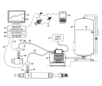
[0009] Figure 1 depicts an embodiment of a system that can be used to
implement the
method.
[00010] Figure 2 depicts an embodiment of the data storage having a plurality
of computer
instructions stored therein.
[00011] Figure 3 depicts a raw pressure data plot, showing raw pressure data
plotted over
time, according to one or more embodiments.
[00012] Figure 4 depicts a plot of test response minus control response,
according to one or
more embodiments.
[00013] Figure 5 depicts an embodiment of the plot of test response minus
control response
with the change in pressure and a change in temperature plotted with respect
to the
change in time.
[00014] Figure 6 depicts a flow diagram of the method for testing the device
for a fluid leak,
according to one or more embodiments.
[00015] The present embodiments are detailed below with reference to the
listed Figures.
2
CA 02798341 2012-12-07
DETAILED DESCRIPTION OF THE EMBODIMENTS
[00016] Before explaining the present system and method in detail, it is to be
understood that
the system and method is not limited to the particular embodiments and that
they can
be practiced or carried out in various ways.
[00017] The present embodiments relate to a system and method for testing
fluid seals, such
as those in connectors or blow out preventers, which can be used for oil
wells, natural
gas well, subsea wells, land based wells, or the like.
[00018] The system and method can help the American economy by reducing the
time and
expense required to begin producing hydrocarbons, thereby lowering the cost of
gasoline and similar petrochemical products, and saving rig time, which can be
about
$50,000 an hour. The system and method can save as much as 30 minutes per
analysis. Analysis of a rig can be performed about 10 times a month; therefore
the
system and method can be used to save about 5 hours a month in analysis time.
As
such, the system and method can be used to save about $250,000 a month in
production costs and about $500,000 a month in production time, based on
current
projected costs.
[00019] The method can include using a pump to simultaneously pump a fluid
from a
reservoir to a control device and a device for testing the device.
[00020] The pump can be a small hand pump, an ENERPAC pump, or any pump
capable of
flowing from about 1 milliliter to about 10 milliliters of gas or fluid into a
test conduit
and adapted to reach a test pressure ranging from about 1000 psi to about
20000 psi.
[00021] The pump can be an electric pump, and the electric pump can be
connected to a
power supply, such as batteries, a 110 volt power supply, generator, or
combinations
thereof.
[00022] The device and the control device can be pressurized. In one or more
embodiments,
the device and the control device can have similar pressures, identical
pressures, or
different pressures.
3
CA 02798341 2012-12-07
[00023] The method can include using a computer program to permit a user to
test at two
different pressures, and then to adjust the pressures to provide a "normal",
thereby
allowing for correct and highly accurate comparisons.
[00024] The method to deteimine leak rates for a fluid in a device can include
determining a
control volume for fluid in the control device at an initial pressure.
[00025] In one or more embodiments, the method can be provide highly accurate
comparisons
for fluid leak rates as low as 1 x 10 -6 cm3/minute or less.
[00026] The control volume can be expanded in the control device by allowing
the control
volume to increase in size by a known volume change, such that pressure
changes
from the initial pressure to an analysis pressure. The known volume change can
range
from only a few microliters to gallons.
[00027] The method can include inserting a valve in a flow line between the
pump and the
control device. The valve can have a stem that can be configured to be rotated
to
provide the known volume change. In operation, the expansion of the control
volume
can be achieved by turning the stem on the valve. For example, a quarter turn
of the
stem on the valve can correlate to a known volume change of 10-6 gallons.
[00028] The increase in volume can cause the pressure drop. An example of the
change from
initial pressure to analysis pressure for the control device can be 200 psi.
[00029] The method can include using a processor with a data storage which can
have
computer instructions stored therein. The data storage can be in communication
with
a pressure transducer on the device being tested and a pressure transducer on
the
control device.
[00030] Information on the fluid can be stored in the data storage. For
example, the fluid can
be water, oil, nitrogen, air, compressed air, compressed nitrogen, compressed
helium,
another compressed inert gas, another liquid, another gas, or combinations
thereof
Also, the fluid can be at a pressure ranging from about 14 psi to about 40,000
psi.
[00031] Information on the test pressure can be stored in the data storage.
For example, the
4
CA 02798341 2012-12-07
test pressure can be 10,600 psi.
[00032] Information on the initial control pressure can be stored in the
data storage. For
example, the initial control pressure can be 10,325 psi.
[00033] Information on the analysis control pressure can be stored in the data
storage. For
example, the analysis control pressure can be 9,500 psi.
[00034] A value for the known volume change can be stored in the data storage.
For example,
the know volume change can range from about 1 milliliter to about 5 barrels.
[00035] Values representing the known volume change can be stored in the data
storage.
Values representing the known value change can vary depending upon the valve
disposed between the pump and the control device, for example the value can
range
from about 1 x 10⁻⁶ gallons to about 1 barrel.
[00036] The method can include simultaneously pressurizing the control device
and the
device that is being tested with fluid. The control device and the device can
be
pressurized at substantially similar initial pressures, such as within a
deviation of +1-
5 percent.
[00037] During pressurization, the fluid used to test the device can be
substantially similar to,
identical to, or different from the fluid used to apply pressure to the
control device.
[00038] The method can include using computer instructions in the data storage
to calculate a
leak calculation ratio by: using the known volume change for the fluid in the
control
device, and dividing the known volume change by a difference between the
initial
pressure and the analysis pressure.
[00039] The method can include providing a determination that no leak is
present in the fluid
seal of the device being tested when the pressure of the device imitates the
control
pressure. For example, testing equipment can provide the determination that no
leak
is present.
[00040] The method can include calculating the difference between the pressure
in the control
5
CA 02798341 2012-12-07
device and the pressure in the device being tested over a defined period of
time to
form a calibration set point.
[00041] The method can include continually calculating the difference between
the pressure in
the control device and the pressure in the device being tested, and comparing
the
calculated difference to the calibration set point.
[00042] If the pressure of the device being tested does not imitate the
pressure of the control
device, then computer instructions in the data storage can be used to
calculate the
difference to form the calibration set point.
[00043] If the difference between the test response and the control response
changes, then a
leak volume can be calculated using the leak calculation ratio.
[00044] For example, if the control device is determined to be at 10,200 psi
and the device
being tested is determined to be at 10,000 psi, the initial difference will be
200 psi,
which forms the calibration set point.
[00045] The method can include comparing the calculated initial difference
over time. The
method can include determining that a leak is present when the calculated
difference
deviates from the calibration set point. Computer instructions in the data
storage can
be used to compare the calculated difference over time and detelinine that
there is a
leak present.
[00046] The method can include multiplying the calculated calibration set
point difference
times the leak calculation ratio to determine a leak volume, such as by using
computer instructions stored in the data storage.
[00047] The method can include dividing the leak volume by the defined period
of time to
provide a leak rate of the device being tested, such as by using computer
instructions
stored in the data storage.
[00048] In one or more embodiments, the method can include using a means for
communicating with the data storage, such as a cell phone, laptop, or computer
monitor. The means for communicating can link to computer instructions in the
data
6
CA 02798341 2012-12-07
storage for comparing the pressure of the device being tested to the pressure
of the
control device.
[00049] The control device can be tested using the fluid with a first test
pressure ranging from
about 5000 psi to about 20,000 psi, while simultaneously testing the device
with the
fluid at a test pressure ranging from about 5000 psi to about 20,000 psi.
[00050] A pressure of the control device can also be referred to as a control
response, and a
pressure of the device being tested, also referred to as a test response, can
be
simultaneously obtained. The pressure transducer on the control device can be
used to
measure and record the control response to the data storage, and the pressure
transducer on the device being tested can be used to measure and record the
test
response to the data storage.
[00051] The test response and the control response can be compared, forming
compared
results which can be presented immediately from the time that the fluid is
pumped to
the control device and the device being tested.
[00052] The computer instructions in the data storage can form compared
results, and can
present the compared results to a user on the means for communicating. Also,
the
means for communicating can form the compared results. In one or more
embodiments, the compared results can be formed immediately from the time of
pumping the fluid to the device being tested and the control device.
[00053] The compared results can be presented to the user on a client device.
The compared
results can be transmitted to a network by the means for communicating, which
can
be in communication with the client device.
[00054] The client device can be a cell phone, laptop, desktop computer,
personal digital
assistant, global positioning system with a display and the processor, or
similar device
with the processor that can be connected to the network.
[00055] The network can be a cellular network, satellite network, local area
network, global
positioning system network, or the internet.
7
CA 02798341 2012-12-07
[00056] Turning now to the Figures, Figure 1 depicts a system that can be used
to implement
the method according to one or more embodiments.
[00057] The system can include a fluid 34 contained in a reservoir 30 or a
secondary source.
[00058] The system can include a pump 50 that can be used to simultaneously
pump the fluid
34 from the reservoir 30 to a device 48 being tested which can have a fluid
seal, while
pumping the fluid 34 from the reservoir 30 to a control device 49. The fluid
34 can be
pumped at the same or similar pressures through flow lines, such as a test
conduit 28
and a control conduit 29.
[00059] The pump 50 can be powered by a power supply 51, such as batteries, a
110 volt
supply from a generator, or an additional power supply.
[00060] The system can include a valve 31 with an integral valve stem 33 that
can be installed
in the control conduit 29. For example, the valve 31 can be a 1/4 inch high
pressure
stem valve, such as those available from Autoclave Engineers of Pennsylvania.
The
integral valve stem 33 can be configured to be rotated to provide known volume
changes of the fluid 34 to the control device 49.
[00061] The pump 50 can pump the fluid 34 into the device 48 through a port
53. The pump
50 can pressure the device 48 to up to about 20,000 psi. In one or more
embodiments,
the device 48 can be a connector, blow out preventer or other device with a
fluid seal.
[00062] The system can include a test pressure transducer 52 and control
pressure transducer
54. The fluid 34 can pass through the test pressure transducer 52 in the test
conduit 28
before passing into the device 48 and through the control pressure transducer
54 in
the control conduit 29 before passing into the control device 49.
[00063] The test pressure transducer 52 can detect pressures in the test
conduit 28, forming a
test pressure signal 56. The test pressure transducer 52 can transmit the test
pressure
signal 56 to a processor 59 in communication with the test pressure transducer
52.
[00064] The control pressure transducer 54 can detect pressures in the
control conduit 29,
forming a control signal 58. The control pressure transducer 54 can transmit
the
8
CA 02798341 2012-12-07
control signal 58 to the processor 59 in communication with the control
pressure
transducer 54.
[00065] The processor 59 can be configured to receive the test pressure signal
56 and control
signal 58 for storage in a data storage 60.
[00066] The processor 59 can store the test pressure signal 56 and the control
signal 58 in the
data storage 60.
[00067] The data storage 60 and the processor 59 can be in communication with
a means for
communicating 74, which can be in communication with a network 72 for
communicating with a client device 70 for remote monitoring.
[00068] The means for communicating 74 can also be in communication with a
display 67,
which can depict an executive dashboard 65 of the testing results for local
monitoring. In one or more embodiments, the executive dashboard 65 can also be
presented on the client device 70.
[00069] Figure 2 depicts an embodiment of the data storage 60 having a
plurality of computer
instructions stored therein.
[00070] The data storage 60 can include computer instructions to instruct the
processor to
determine a difference between the test response and the control response to
form a
pressure difference 200.
[00071] The data storage 60 can include computer instructions to instruct the
processor to
determine a drop in the pressure difference associated with the known volume
202.
[00072] The data storage 60 can include computer instructions to instruct the
processor to
form a leak test ratio by dividing the known volume by the drop in the
pressure
difference 204.
[00073] The data storage 60 can include computer instructions to instruct the
processor to
determine if the test response imitates the control response by determining if
a change
in the pressure difference occurs 206.
9
CA 02798341 2012-12-07
[00074] In operation, if imitation is determined, the processor can be
configured to use
computer instructions to provide a determination that no leak in the fluid
seal of the
device is present 208.
[00075] In operation, if imitation is not determined, the processor can
be configured to use
computer instructions to determine a leak volume by multiplying a pressure
drop
associated with the change in the pressure difference by the leak test ratio,
and to
provide a determination that a leak in the fluid seal of the device is present
210.
[00076] The data storage 60 can include computer instructions to instruct the
processor to
determine a time period associated with the leak volume and dividing the leak
volume
by the time period to form a leak rate 212.
[00077] The data storage 60 can include computer instructions to instruct the
processor to
form a plot of the pressure difference over time 214.
[00078] The data storage 60 can include computer instructions to instruct the
processor to
present the plot of the pressure difference over time as the executive
dashboard to the
user on the client device, the display, or combinations thereof 216.
[00079] The data storage 60 can include information about the fluid 218, a
value for the
known volume 220, and a value representing the known volume 222 stored
therein.
[00080] The data storage 60 can include computer instructions to
simultaneously pressurize
the control device and device being tested with the fluid at substantially
similar initial
pressures 224.
[00081] For example, the initial pressures can be within a deviation of
about +/- 5 percent.
During simultaneously pressurization, the fluid used to pressurize the device
being
tested and the fluid used to pressurize the control device can be identical,
substantially similar, or different.
[00082] Figure 3 depicts a raw pressure data plot 112, showing raw pressure
data plotted over
time, according to one or more embodiments.
CA 02798341 2012-12-07
[00083] The raw pressure data plot 112 can include a plot of detected pressure
of the device
being tested as a test line 110.
[00084] The raw pressure data plot 112 can include a plot of detected pressure
of the control
device as a control line 114.
[00085] The control line 114 can have a pressure reduction at about halfway
through a
pressure test at a point 116, which can be due to a volume increase. The
volume
increase can be initiated by a 1/4 inch turn on the stem of the valve in the
control
conduit. The diameter of the stem on the valve and the pitch of the thread
connecting
the stem to the valve can be known; therefore the volume increase can be
calculated
using computer instructions in the data storage.
[00086] The test line 110 can be depicted imitating the control line 114,
which can indicate
that there is no leak in the device being tested.
[00087] Figure 4 depicts a plot of test response minus control response 104,
according to one
or more embodiments.
[00088] The plot of test response minus control response 104 can include a
change in pressure
99 and a change in time 101. The change in pressure 99 can be plotted with
respect to
the change in time 101.
[00089]
A first portion of the curve 100 represents a start of the test for fluid
leaks, with the
initial pressure of both being the same and remaining substantially the same
until a
midpoint of the curve 102, which can be about halfway through the test for
fluid
leaks. A 1/4 inch turn of the stem of the valve in the control conduit can
initiate the
pressure difference depicted at the midpoint of the curve 102.
[00090] Turning the stem of the valve can open the valve and cause the fluid
to flow through
the valve, thereby increasing the volume of fluid in the control device. The
difference
in the volume of fluid before and after turning the stem of the valve can be
referred to
as a control volume.
11
CA 02798341 2012-12-07
[00091] The control volume can be calculated based on the valve stem diameter
and valve
stem thread pitch. For example, the control volume can be 1 x 10⁻⁶ gallons,
which can
result in a pressure difference of 60 psi, which is indicated at a pressure
drop point of
the curve 103.
[00092] In one or more embodiments, the plot of test response minus control
response 104 can
be formed using computer instructions stored in the data storage.
[00093] The plot of test response minus control response 104 can make evident
whether or not
there is a fluid leak in the fluid seal of the device being tested.
[00094] The plot of test response minus control response 104 is depicted with
no leak present,
which is evident due to the lack of a change in pressure difference except for
at the
midpoint of the curve 102 where a 1/4 inch turn of the stem of the valve in
the control
conduit was initiated.
[00095] Figure 5 depicts an embodiment of the plot of test response minus
control response
104 with the change in pressure 99 and a change in temperature 98 plotted with
respect to the change in time 101.
[00096] The first portion of the curve 100 represents a start of the test
for fluid leaks, with the
initial pressure of both remaining substantially the same until the midpoint
of the
curve 102, at which a 1/4 inch turn of the stem of the valve in the control
conduit has
been initiated to cause the depicted pressure difference.
[00097] Turning the stem of the valve in the control conduit can cause the
change in pressure
to drop to the pressure drop point of the curve 103.
[00098] After the pressure drop point of the curve 103, the change in pressure
99 can be
shown dropping slowly over the change in time 101, as indicated by a leak
portion of
the curve 105, which is indicative of a fluid leak in the fluid seal of the
device being
tested.
[00099] In operation, the known volume change can be introduced halfway
through the test,
allowing a leak rate to be defined.
12
CA 02798341 2012-12-07
[000100] The leak rate can be calculated using the change in volume and the
change in time in
which the change in volume occurred can be determined, such as by using
computer
instructions in the data storage. For example, a 1 x 10⁻⁶ gallon reduction in
volume
over five minutes can be equated with a leak rate of 0.00029 gallons per day.
[000101] In the depicted embodiment, a 1/4 inch turn of the stem of the valve
was initiated at
about 150 seconds into the test, and he fluid leaking stopped at about 400
seconds
into the test. The leak volume can be estimated. For example, if 60 psi is a
known
leak volume of 1 x 10⁻⁶ gallons, and the actual leak volume is 90 psi over
about 250
second, it can be estimated that the leak rate is about 0.00045 gallons per
day.
[000102] Environmental effects, such as weather, 0-ring extrusion, and the
like can be
cancelled out because the difference between the test response and the control
response is measured. Also, the control device can be visually inspected for
fluid
leaks to ensure accurate test results. As such, deviations on the plot of test
response
minus control response 104 can be determined to be due to leaks, unless the
control
device is not in under the same environmental conditions as the device being
tested.
[000103] A temperature line 107 for the change in temperature 98 can be
plotted along with the
change in pressure 99. In operation, if the change in temperature 98 rises and
the
change in pressure 99 rises, this can be indicative that the device being
tested is being
heated relative to the control device. If the change in temperature 98 rises
and the
change in pressure 99 drops, this can be indicative of a fluid leak in the
device being
tested.
[000104] In operation, multiple devices can be stacked or connected together,
such that
multiple fluid seals can be tested simultaneously. For example, a 3/8 inch and
two 1/4
inch connections can be tested by screwing together the connectors.
[000105] Figure 6 depicts a flow diagram of the method for testing the device
for a fluid leak,
according to one or more embodiments. The fluid leak can have a rate of less
than 1 x
10-6 cm3 per minute.
13
CA 02798341 2012-12-07
[000106] The method can include connecting the device to the pump connected to
the reservoir
of fluid, wherein the device has a fluid seal, as illustrated by box 600.
[000107] The device can be a blowout preventer, a connector, a plurality of
connectors, or
multiple devices stacked or connected together for a well. Multiple devices
can be
simultaneously tested.
[000108] For example, the fluid can be: water, compressed air, oil, compressed
nitrogen,
compressed helium, another compressed inert gas, another gas, another fluid,
and
combinations thereof The fluid can be at a pressure ranging from 14 psi to
40,000
psi.
[000109] The method can include connecting the control device to the pump, as
illustrated by
box 602.
[000110] The method can include simultaneously pumping the fluid into the
device and the
control device, as illustrated by box 604.
[000111] The fluid can be pumped to the device and the control device at a
pressure ranging
from 5000 psi to 20,000 psi. In operation, identical pressures can be provided
to the
device and the control device using the fluid.
[000112] The method can include detecting a pressure of the fluid flowing to
the control
device, forming a control response, as illustrated by box 606.
[000113] The method can include detecting a pressure of the fluid flowing to
the device,
forming a test response, as illustrated by box 608.
[000114] For example, the pressures can be detected using pressure transducers
in
communication with the processor, the processor can be in communication with
the
data storage, and the data storage can have computer instructions for storing
the
detected pressures.
[000115] For example, computer instructions in the data storage can be used to
form the test
response and the control response.
14
CA 02798341 2012-12-07
[000116] The method can include determining a difference between the test
response and the
control response, forming a pressure difference, as illustrated by box 610.
[000117] For example, computer instructions in the data storage can be used to
form the
pressure difference.
[000118] The method can include adjusting a volume of the fluid in the control
device by a
known volume, as illustrated by box 612.
[000119] For example, the volume of the fluid in the control device can be
adjusted using a
stem of the valve. The valve can be in fluid communication between the pump
and
the control device, and the stem can be configured to be rotated to provide
the known
volume. The known volume can range from about 1 x 10⁻⁶ gallons to about 1
barrel.
[000120] The method can include determining a drop in the pressure difference
associated with
the known volume, as illustrated by box 614.
[000121] For example, computer instructions in the data storage can be used to
determine the
drop in the pressure difference associated with the known volume.
[000122] The method can include forming a leak test ratio by dividing the
known volume by
the drop in the pressure difference, as illustrated by box 616.
[000123] For example, computer instructions in the data storage can be used to
form the leak
test ratio.
[000124] The method can include determining if the test response imitates the
control response
by determining if a change in the pressure difference occurs, as illustrated
by box
618.
[000125] For example, computer instructions in the data storage can be used to
determine if the
test response imitates the control response.
[000126] The method can include providing a determination that no leak in the
fluid seal of the
device is present if imitation is determined, as illustrated by box 620.
CA 02798341 2012-12-07
[000127] The method can include determining a leak volume by multiplying a
pressure drop
associated with the change in the pressure difference by the leak test ratio,
and
providing a determination that a leak in the fluid seal of the device is
present if
imitation is not determined, as illustrated by box 622.
[000128] For example, computer instructions in the data storage can be used to
provide the
determination that no leak in the fluid seal of the device is present, or
determine the
leak volume and provide the determination that the leak in the fluid seal of
the device
is present.
[000129] The method can include determining a time period associated with the
leak volume
and dividing the leak volume by the time period, forming a leak rate, as
illustrated by
box 624.
[000130] The method can include storing in the data storage: information about
the fluid, a
value for the known volume, and a value representing the known volume, as
illustrated by box 626.
[000131] For example, the value representing the known volume can be a degree
of turn
associated with a known volume.
[000132] The method can include forming a plot of the pressure difference over
time, as
illustrated by box 628.
[000133] The method can include using a means for communication to transfer
the plot of the
pressure difference over time to a user, as illustrated by box 630.
[000134] For example, the means for communication can be in communication with
the
processor, the data storage, or combinations thereof.
[000135] The method can include presenting the plot of the pressure difference
over time as the
executive dashboard to the user on the client device, the display, or
combinations
thereof, as illustrated by box 632.
16
CA 02798341 2012-12-07
[000136] For example, the client device and the display can each be: a cell
phone, a laptop, a
desktop computer, a personal digital assistant, a global positioning system,
or similar
device that is connectable to the network.
[000137] While these embodiments have been described with emphasis on the
embodiments, it
should be understood that within the scope of the appended claims, the
embodiments
might be practiced other than as specifically described herein.
17