Note: Descriptions are shown in the official language in which they were submitted.
CA 02798414 2012-12-12
1
Method for operating a machine located in choppy waters
Description
The present invention relates to a method for operating a
machine, in particular a wave energy converter, located in
choppy waters, for converting energy from a wave movement of
a fluid into another form of energy, a computing unit for
carrying out said method and a correspondingly operated wave
energy converter.
Prior art
Wave power plants (wave energy converters) utilize the
energy from sea waves to acquire electric current.
Relatively new design approaches use rotating units here
which convert the wave movement into a torque. In said
units, inter alia hydro-dynamic floating bodies, (i.e.
bodies which generate lift when there is a flow around them)
are used as coupling bodies by means of which a lift moment
is generated from the incoming wave, which lift moment can
be converted into a rotational movement of a rotor. The
corresponding coupling bodies are arranged, for example, on
a crank drive. Lift forces are produced at the coupling
bodies by a superimposed incoming flow from the orbital flow
of the wave movement and the coupling bodies own rotation,
which lift forces cause a torque to be introduced into the
crank drive.
The lift of a hydrodynamic lift body can be changed by means
of its pitch angle with respect to the medium which is
flowing against them, for example air or water. In
particular, for such rotating wave power plants with
hydrodynamic floating bodies reliable adjustment is
important since desynchronization of the rotor from the
orbital flow as a result of vortex breakdown can lead to
complete decoupling from the shaft.
CA 02798414 2012-12-12
2
In particular, owing to the multichromatic wave states of
sea waves it is necessary to perform open-loop and/or
closed-loop control of a corresponding system in such a way
that there is always an optimum flow against the flow bodies
and that the flow bodies are operated as close as possible
to the conversion optimum. As a result, a maximum energy
yield can be achieved. Actuation variables are here, in
particular, the generator torque and the adjustment of the
pitch angle of the coupling bodies. This results in
corresponding angles of flow against the coupling bodies and
a phase angle between the rotation of the system and the
wave orbital flow.
US 7,686,583 B2 proposes determining an incoming flow angle
of a fluid flowing against a coupling body, on the basis of
a measured lift in conjunction with the flow speed. For this
purpose, different measuring means, including pressure
sensors, are provided. On this basis, it is then possible to
perform a control which comprises, for example, adjustment
or torsion of the coupling bodies in order to adapt them to
an oblique incoming flow or a corresponding re-alignment of
the total system. However, in particular local differences
at a coupling body cannot be detected by the method
disclosed in said document. The method also permits no
conclusions to be drawn about an imminent or already
occurred vortex breakdown.
Therefore, there is still the need for improved
possibilities for operating a wave energy converter.
Disclosure of the invention
According to the invention, a method for operating a
machine, in particular a wave energy converter, located in
choppy waters, for converting energy from a wave movement of
a fluid into another form of energy, a computing unit for
carrying out said method and a correspondingly operated wave
CA 02798414 2012-12-12
3
energy converter having the features of the independent
patent claims are proposed. Advantageous refinements are the
subject matter of the dependent claims and of the following
description.
Advantages of the invention
Within the scope of the invention, on the basis of
measurement variables of a first, relatively early time a
prediction of a wave movement at a second, relatively late
time is made, as a result of which the operation of the
machine can be significantly improved, in particular pilot
control can take place with the result that control errors
which occur are reduced. As a result, the control
interventions can be reduced and the control becomes more
robust. The operation becomes less reactive.
The invention proposes a method and a measuring system which
can be used to determine a three-dimensional speed potential
from which, inter alia, a speed field can then be derived.
As a result, the current flow conditions are known, which
can be used for particularly efficient pilot control of the
machine. In particular, a measuring method for cost-
effective and robust 3D data acquisition is proposed.
Various prediction possibilities are specified with which
the measurement data which are obtained can be extrapolated
chronologically and spatially.
According to one aspect of the invention, a wave energy
converter is operated. The invention proposes a method which
permits pilot control of the manipulated variables (in
particular generator torque and/or pitch angle of the
coupling bodies). The operation preferably comprises a
control process, wherein the controlled variable can be a
phase angle between a rotational movement of a rotor of the
wave energy converter and an orbital flow of the wave
movement. With respect to further details relating to
CA 02798414 2012-12-12
4
engagement possibilities and/or control possibilities for
the energy conversion reference
is made to
DE 10 2011 105 177 which was published after the priority
date of the present document and whose disclosure is made
part of the present invention. As a result, the control
interventions can be reduced and the control process becomes
more robust. The operation of the wave energy converter is
improved since there is less need to react to changes which
have already occurred (which leads to worsening of the
energy acquisition) and instead of which, by way of pilot
control, the wave energy converter is already set to
expected changes (which reduces or even prevents worsening
of the energy acquisition). The conversion efficiency is
increased. This applies, in particular, to multichromatic
wave states which make particularly stringent requirements
of the open-loop/closed-loop control of wave energy
converters. Furthermore,
particularly advantageous
possibilities are provided in respect of protective
measures.
In particular for wave energy converters which utilize the
hydrodynamic lift principle, very good knowledge of the flow
field is decisive since in the case of incorrect open-loop
and/or closed-loop control decoupling of the machine from
the local incoming flow and therefore the wave movement can
occur. In this case, the efficiency of the system would
decrease significantly. In addition, the mechanical loading
of the machine would increase significantly. Within the
scope of the invention, the flow field which is induced at
the wave energy converter by the waves is calculated in
order to permit the machine to be controlled.
Furthermore, flow which is superimposed on the orbital flow
can be detected with the presented system and integrated
into the calculation. Since this flow is superimposed on the
orbital flow of the wave movement, inclusion in the
CA 02798414 2012-12-12
calculation is advantageous in order to increase the
conversion efficiency.
A preferred predictable variable which characterizes the
5 wave movement expected at the second, relatively late time,
is a speed field or flow field or a speed potential. In this
context, the invention advantageously utilizes the property
of sea waves in that within the scope of the inventive
application they can be modeled very well as a speed
potential since viscous effects have little influence within
the scope of the described application of the invention. A
speed field is in a vector field which assigns a speed
vector to every location in the space.
According to another aspect, the invention can also be used
in areas in which a prediction of the wave movement provides
advantages for the operation or the safety of a technical
sea design. The operation can comprise, for example, placing
in a position of rest (for example vane position in the case
of coupling bodies of wave energy converters). Furthermore,
offshore operations can be carried out more efficiently (for
example the depositing of a load from a moving ship onto an
oil platform or onto the seabed). However, in particular the
invention can be used in wave power plants in order to
increase the conversion efficiency. In this context, the
invention can be particularly advantageously utilized for
the concerted control of multiple power plants (parks). This
applies, in particular, to the case in which the absorption
characteristic and/or irradiation characteristic of the
individual power plants is known and can be described by
suitable models.
An initial speed field or initial speed potential is
preferably determined at a first location at a first,
relatively early time on the basis of measured values, and
on the basis of the initial speed field or initial speed
potential a result speed field or result speed potential is
CA 02798414 2012-12-12
6
determined at a second location at a second, relatively late
time. The second location is expediently the location of the
respective wave energy converter, and the first location can
be the same location, but it is preferably on the side
facing the incoming wave, at a certain distance from the
wave energy converter or the park.
In the paper "Direct Simulation and Deterministic Prediction
of Large-Scale Nonlinear Ocean Wave-field" by Guangyu Wu,
Department of Ocean Engineering,
MIT,
(http://hdl.hand1e.net/1721.1/33450), a method is described,
for example in the context of shipping, with which on the
basis of measurement variables an initial wave field is
determined and the initial wave field is developed further
over time in order to predict an expected wave field. The
orders of magnitude which are considered comprise several
100 km there. The determination of the initial wave field
uses Stokes equations (cf. for example Schwartz, L.W., 1974,
Computer extension and analytic continuation of Stokes'
expansion for gravity waves, J. Fluid Mech., Vol. 62, 553-
578) of a low order (up to the 2nd) for waves with a small
height and in addition a nonlinear spectral analysis of a
relatively high order (HOS; cf. for example Dommermuth, D.G.
& Yue, D.K.P., 1987, A high-order spectral method for the
study of nonlinear gravity waves, J. of Fluid Mech. 184) for
waves with a relatively large height. The development over
time likewise uses an HOS method.
The HOS method is capable of efficiently calculating the
development over time of, for example, speed potentials with
high accuracy. In order to be able to perform a development
over time, it is necessary to know the current speed
potential (initial potential) in order to be able to use
this as initial conditions in the HOS. In the paper by Wu, a
systematic generation of these initial conditions is carried
out for the first time. The generation is based on the
measurement data of a sensor system. By suitable correlation
CA 02798414 2012-12-12
7
of the sensors it is possible to determine the initial
potential.
Within the scope of the invention it has been realized that
this method can surprisingly also be used on much smaller
scales (the orders of magnitude which are relevant for wave
energy converters comprise only up to a few 100 m) and are
therefore very well suited for actuating or operating wave
energy converters. Within the scope of the invention,
preferably both the initial speed potential and the result
speed potential are now determined on the basis of the
method described there. This predetermined result speed
potential can be used, in particular, for pilot control of
the wave energy converter, for example for the generator
torque control and/or pitch control.
In a further advantageous refinement, the reaction of a wave
energy converter to the speed potential is determined in
order, for example, to be able to efficiently use wave
energy converter parks. The described HOS method can also be
used for this purpose.
A computing unit according to the invention, for example a
control device of one or more wave energy converters is
configured, in particular in programming terms, to carry out
a method according to the invention.
The implementation of the invention in the form of software
is also advantageous since this permits particularly low
costs, in particular if an executing computing unit is still
being used for other tasks and is therefore present in any
case. Suitable data carriers for making available the
computer program are, in particular, disks, hard disks,
flash memories, EEPROMs, CD-ROMs, DVDs etc. It is also
possible to download a program via computer networks
(Internet, Intranet etc.).
CA 02798414 2012-12-12
8
Further advantages and refinements of the invention can be
found in the description and the appended drawing.
Of course, the features which are mentioned above and which
are to be explained further below can be used not only in
the respectively specified combination but also in other
combinations or alone without departing from the scope of
the present invention.
The invention is illustrated schematically with reference to
exemplary embodiments in the drawing and is described in
detail below with reference to the drawing.
Description of figures
In the drawing:
Figure 1 shows a wave energy converter having a rotor with
two coupling bodies in a side view and illustrates
the pitch angle y and the phase angle between
the rotor and the orbital flow,
Figure 2 shows resulting incoming flow angles al and a2 and
resulting forces at the coupling bodies of the
rotor from Figure 1, and
Figure 3 illustrates, in a side view,
a possible
arrangement of sensors on and around a wave energy
converter for converting energy from a wave
movement.
Detailed description of the figures
In the figures, identical or identically acting elements are
indicated with identical reference symbols. For the sake of
clarity, a repeated explanation will not be given.
CA 02798414 2012-12-12
9
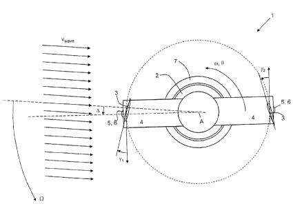
Figure 1 illustrates a wave energy converter 1 such as can
be used as a basis for the present invention, having a
housing 7 and a rotor 2, 3, 4 which is rotatably mounted
thereon and has a rotor base 2 and two coupling bodies 3
which are each attached in a rotationally fixed fashion to
the rotor base 2 by means of lever arms 4. The rotor 2, 3, 4
is assumed to be arranged underneath the water surface of a
body of water with wave action - for example an ocean. In
this context, there will preferably be deep water conditions
present in which the orbits of the water molecules run in a
largely circular fashion. The rotational axis A of said
rotor will be assumed to be oriented largely horizontally
and largely perpendicularly with respect to the current
propagation direction of the waves of the rippled body of
water. The coupling bodies 3 are embodied in the example
shown as hydrodynamic lift bodies. The rotating components
of the wave energy converter are preferably provided with a
largely neutral lift in order to avoid a preferred position.
This applies, in particular to components of the rotor which
are asymmetrical with respect to the rotational axis and do
not have any "corresponding part" which is arranged with
point symmetry.
The coupling bodies 3 are arranged at an angle of
approximately 1802 with respect to one another. The coupling
bodies are preferably secured in the vicinity of the
pressure point thereof in order to reduce rotational torques
which occur during operation and act on the coupling bodies,
and in this way to reduce the requirements made of the
mounting means and/or the adjustment devices.
The radial distance between the suspension point of a
coupling body and the rotor axis is 1 m to 50 m, preferably
2 m to 40 m, particularly preferably 4 m to 30 m and quite
particularly preferably 5 m to 20 m.
CA 02798414 2012-12-12
Two adjustment devices 5 for adjusting the pitch angles yl
and y2 of the coupling bodies 3 between the vane chord and
the tangent are additionally illustrated. The two pitch
angles yi and y2 are preferably oriented in opposite
5 directions and preferably have values of
-202 to +202. However, in particular when starting up the
machine larger pitch angles can also be provided. The pitch
angles yi and y2 can preferably be adjusted independently of
one another. The adjustment devices can preferably be
10 electromotive adjustment devices, preferably with stepping
motors, and/or can be hydraulic and/or pneumatic components.
The two adjustment devices 5 can additionally each be
assigned a sensor system 6 for determining the current pitch
angles yl and y2. A further sensor system (not illustrated)
can determine the rotational angle of the rotor base 2 with
respect to the housing 7.
The orbital flow flows against the wave energy converter 1
with an incoming flow speed of vw ave. This incoming flow is
the orbital flow of sea waves whose direction changes
continuously. In the illustrated case, the rotation of the
orbital flow is oriented in the counterclockwise direction,
and the associated wave therefore propagates from right to
left. In the monochromatic case, the incoming flow direction
changes here with the angular speed Q = 2nf = const., where
f is the frequency of the monochromatic wave. In contrast,
in multichromatic waves, Q is subject to a change over time,
= f(t) since the frequency f is a function of time, f =
f(t). There is provision that the rotor 2, 3, 4 rotates
synchronously with the orbital flow of the wave movement
with an angular speed co, wherein the term synchronicity is
to be understood as averaged over time. In this context, for
example Q co. A value or a value range for an angular speed
co of the rotor is therefore predefined on the basis of an
angular speed Q of the orbital flow or adapted thereto. In
CA 02798414 2012-12-12
11
this context, constant control or brief or short-term
adaptation can take place.
As is explained in more detail below, a first torque which
acts on the rotor 2, 3, 4 is generated as a result of the
effect of the flow with the incoming flow speed vwave against
the coupling bodies.
Furthermore there is provision that a preferably variable
second torque in the form of a resistance, that is to say
breaking torque, or an acceleration torque, can be applied
to the rotor 2, 3, 4. Means for generating the second torque
are arranged between the rotor base 2 and the housing 7.
There is preferably provision here that the housing 7 is the
stator of a directly driven generator and the rotor base 2
is the rotor of this directly driven generator whose
bearing, windings, etc. are not illustrated; here, the
second torque is determined by the generator torque.
However, as an alternative to this, other drive train
variants can also be provided in which the means for
generating the second torque comprise, in addition to a
generator, also a transmission and/or hydraulic components
such as, for example, pumps. The means for generating the
second torque can additionally or else exclusively comprise
a suitable brake.
Between the rotor orientation, which is illustrated by a
lower dashed line which runs through the rotor axis and the
center of the two adjustment devices 5, and the direction of
the orbital flow which is illustrated by an upper dashed
line which runs through one of the speed arrows vwave I there
is a phase angle L whose absolute value can be influenced by
adjusting the first and/or second torques. In this context,
a phase angle from -452 to 452, preferably from -252 to 252
and particularly preferably from -152 to 152, appears
particularly advantageous for generating the first torque
since here the orbital flow vwave and the incoming flow are
ak 02798414 2012-12-12
12
largely perpendicularly oriented with respect to one another
owing to the intrinsic rotation vrotor (see Figure 2), which
leads to a maximization of the rotor torque. Maintaining the
required synchronicity means A
const., wherein oscillation
about a mean value of A is also understood to be
synchronous. The illustration of the coupling bodies in
Figure 1 and in the further figures is then given merely by
way of example for the definition of the different machine
parameters. During operation, the pitch angles of the two
coupling bodies are preferably embodied in an opposed
fashion to that in the illustration. The coupling body on
the left in Figure 1 would then be adjusted toward the
inside and the right-hand coupling body in Figure 1 toward
the outside. In this context, in contrast to this schematic
illustration with uncurved symmetrical profiles it is also
possible, in particular, to provide for the use of other
profile geometries which can also be adapted and/or
transformed with respect to the circular path.
Within the scope of the invention, it is possible to
determine, in particular, vw ave and Q(t) in advance on the
basis of the previously determined result speed potential,
and pilot control of the first and/or second torque can
therefore be carried out correspondingly. In this context,
in the case of small rotor diameters it may be sufficient to
determine the flow vector at the center point of the rotor.
In contrast, in the case of relatively large rotor diameters
knowledge of the local flow vector at the coupling bodies is
advantageous. The first torque is influenced substantially
by means of the pitch angles yi and y2 as well as by means of
the phase angle A between the rotation co and orbital flow Q
and the resulting incoming flow speed, and the second torque
is influenced by means of the torque which is tapped from
the generator and which can be influenced, for example, by
predefining the exciter current of the rotor.
CA 02798414 2012-12-12
13
Figure 2 is a schematic illustration of the resulting
incoming flow ratios and the forces which occur at the
coupling bodies which give rise to a rotor torque. In this
context, it is assumed in a simplifying fashion that the
flow is embodied uniformly over the entire rotor cross
section and has the same absolute value and the same
direction. However, in particular for rotors with large
radial extents, in particular in the case of the illustrated
horizontal orientation of the lever arms 4 the various
coupling bodies 3 of the rotor 2, 3, 4 may be located at
different positions relative to the wave, which gives rise
to a locally different incoming flow direction. However,
this may be compensated, for example, using an individual
setting of the respective pitch angle y.
Figure 2 illustrates, on both coupling bodies, the local
incoming flows as a result of the orbital flow (vwave,i) and
as a result of the intrinsic rotation (vrotor,i), the incoming
flow speed (Vresulting, ) resulting from these two incoming
flows, and the resulting incoming flow angles al and a2.
Furthermore, the lift forces and resistance forces Flift,, and
Fresisti which occur at the two coupling bodies are also
derived and are dependent both on the absolute value of the
incoming flow speed and on the incoming flow angles al and a2
and therefore also on the pitch angles yi and y2 and are
oriented perpendicularly or parallel with respect to the
direction of Vresulting,i=
For the illustrated case, the two lift forces Flift,i result
in a rotor torque in the counterclockwise direction, and the
two resistance forces Fresist,i result in a rotor torque which
is relatively small in terms of absolute value and is in the
opposite direction (that is to say in the clockwise
direction). The sum of the two rotor torques brings about a
rotation of the rotor 2, 3, 4 whose speed can be set by the
adjustable second torque.
ak 02798414 2012-12-12
14
If synchronicity where A const. is reached, from Figure 2
it is immediately apparent that for monochromatic cases in
which the absolute value of the flow vwave,i and the angular
speed Q remain constant, the incoming flow conditions of the
two coupling bodies 3 do not change over the rotation of the
rotor. This means that at constant pitch angles y a largely
constant rotor torque is generated which can be tapped with
a constant second torque of a corresponding generator. In
contrast, in the case of multichromatic waves, changes occur
in the angular speed Q and in the absolute value vwave which
can be taken into account by adapting the pitch angles
and/or the second torque. This is particularly
advantageously achieved by means of pilot control on the
basis of the present invention.
From the forces which act on the coupling bodies, there is,
in addition to a rotor torque, also a resulting rotor force
as a result of vectorial addition of Flift,li Fresist,lr Flift,2
and Fresist,2= The latter acts as a bearing force on the
housing and must be correspondingly supported if
displacement of the housing is undesired. While the rotor
torque remains constant when identical incoming flow
conditions are assumed (vwave, 1 r A,Qr (Or a2,Yl, Y2
const.), this applies to the resulting rotor force only in
terms of absolute value. The direction of the rotor force
also changes correspondingly owing to the constantly
changing direction of flow of the orbital flow and the
synchronous rotor rotation. In the case of multichromatic
waves, the absolute value of the rotor force also changes
continuously in addition to the direction.
In addition to the rotor torque being influenced by an
adjustment of the rotor angles y and/or an adjustment of the
phase angle 4, the absolute value and direction of this
rotor force can also be influenced by changing the pitch
angles y (as a result of which the incoming flow angles a
change), by changing the rotor angle speed co and/or the
CA 02798414 2012-12-12
phase angle - for example by changing the generator torque
which is applied as a second torque (as a result of which
vrotor changes), and/or by means of a combination of these
changes. In this context, the synchronicity which is
5 described in the introduction is preferably maintained.
Figure 3 shows different preferred sensor positions for
mounting sensors for determining the flow conditions on a
wave energy converter 20, and particularly preferably for
10 determining the local incoming flow conditions at the
coupling bodies of a wave energy converter. Furthermore, the
movement behavior of the wave energy converter 1 can also be
determined with sensors mounted thereon. A wave propagation
direction is denoted by W. The wave energy converter 20 is
15 equipped with a frame for positional stabilization, the
frame is in turn equipped with a mooring for maintaining the
position and together with a hydrostatic lift system for
supporting the second torque.
In order to selectively influence the rotor forces,
knowledge of the incoming flow ratios at the coupling
bodies, and in particular the local flow speed and flow
direction, is advantageous. For this purpose, sensors can be
arranged on the rotor (position 101, 20) and/or on the
coupling bodies (position 102) and/or on the frame (position
103) and/or floating under the surface of the water in the
vicinity of the machine (position 104) and/or on the surface
of the water in the vicinity of the machine (position 105)
and/or on the seabed underneath the machine (position 106)
and/or floating under the surface of the water mounted
(position 107) ahead of the machine (or of a park composed
of a plurality of machines) and/or mounted (position 108)
ahead of the machine (or of a park composed of a plurality
of machines) on the seabed, and/or mounted (position 109) in
a floating fashion ahead of the machine (or of a park
composed of a plurality of machines) and/or above the
surface of the water (position 110), for example in a
CA 02798414 2012-12-12
16
satellite. Additional sensors 105' to 109' can be arranged
on the leeside with respect to the wave propagation
direction. Such leeside sensors permit interaction of the
wave energy converter with entered waves to be determined.
On the basis of this knowledge, the result of the
interaction can be checked and, if appropriate, the
interaction can be changed in a targeted fashion by means of
a machine control process.
In this context, sensors and corresponding combinations,
inter alia from the following classes, can be used:
= pressure sensors (for determining the difference
and/or absolute pressure) for determining hydrostatic
(wave height) and/or hydrodynamic (incoming flow)
pressures; in particular in the case of a different
geometric orientation for sensing different,
preferably orthogonal, measuring directions it is
possible to acquire a complete measuring image. This
is converted from a punctiform system into a 3D
system by superimposition of a plurality of measuring
points.
= ultrasound sensors for determining flow rates (for
example by means of particles carried along in the
fluid), advantageously in a plurality of dimensions.
= laser sensors for determining flow rates and/or a
geometry of a water surface in order to determine a
propagation direction and the wave height, and the
propagation speed derived therefrom.
= radar sensors for determining the surface geometry.
= acceleration sensors for determining flow ratios
and/or movements of the entire system and/or of the
rotor and/or of the surface speeds of the body of
water and/or for determining the orientation of a
body, in particular of the rotor, by detecting the
earth's gravitational field;
(for example acceleration sensors which are carried
CA 02798414 2012-12-12
17
along in floating bodies with neutral lift such as,
for example, balls, which acceleration sensors can
sense the flow speed and direction by means of the
current acceleration values; the transmission of the
measurement signals can occur, for example, by radio.
In addition to a "free swimming" body it is also
possible for the latter to be suspended from a joint;
the movements can also be evaluated with acceleration
sensors, wherein the movements are restricted to 2D
unless the connecting rod is of telescopic design).
= inertial sensors for measuring different
translational and/or rotational acceleration forces.
= mass flow meter/flow sensors and hot wire
anemometers for determining a flow speed.
= Bending transducers for determining a flow speed (by
means of the degree of deformation).
= Expansion sensors for determining the deformation of
the coupling bodies.
= Anemometers for determining a flow speed.
= Angle sensors (absolute or incremental), tachometers
for determining pitch angles of the coupling bodies
and/or of the rotational angle of the rotor.
= Torque sensors for determining the adjustment forces
and/or holding forces of the coupling body adjustment
system.
= Force sensors for determining the rotor force in
terms of absolute value and direction.
= Satellites for determining the surface geometry of
the ocean region.
= GPS data for determining machine position and/or
movement.
= Gyroscopes for determining a rotational rate.
= Measuring bodies floating on the surface, such as
for example buoys (up and down movement, rocking
movement); the movements here can also be sensed in
all spatial directions with acceleration sensors (for
example gyroscopically suspended ones).
CA 02798414 2012-12-12
18
The instantaneous local incoming flow conditions of the
coupling bodies and/or the flow field around the machine
and/or the flow field running into the machine/park composed
of a plurality of machines and/or the natural oscillations
of the machine can, in particular, be determined
predictively from these sensor signals with the result that
the second braking torque and/or the pitch angles y of the
coupling bodies 3 can be suitably set in order to achieve
the open-loop/closed-loop control objectives. This can be
done, in particular, by using the HOS method explained at
the beginning.
The open-loop/closed-loop control objectives include not
only optimizing the rotor torque but also, in particular,
maintaining synchronicity and/or avoiding a vortex breakdown
at the coupling bodies and/or influencing the rotor forces
in order to stabilize them and/or shift them and/or
selective excitation of oscillations and/or rotation of the
system in order to bring about positionally correct
orientation with respect to the incoming wave. In addition,
by means of the open-loop/closed-loop control together with
changing of the at least one lift system it is also possible
to influence the immersion depth and the supporting torque.
By adapting the damping plate resistance it is also possible
to influence the machine oscillation behavior. The open-loop
and closed-loop control within the scope of the invention is
advantageously carried out by taking into account the
previously determined result speed potential. In this
context, within the scope of this application the term
synchronicity is considered to be fulfilled when the rotor
rotates synchronously with the flow vector of at least one
main component of the wave.
In this context, measurements of the flow field which
already take place ahead of the machine or a park composed
of a plurality of machines, and from which the flow field
CA 02798414 2012-12-12
19
which is present at the machine or machines at a relatively
late time can be calculated, appear particularly
advantageous. Together with a virtual model of the machine,
pilot control of the manipulated variables can be derived
therefrom and then adapted by means of an adjustment
process. By means of such a procedure, in multichromatic
states of the sea it is possible, in particular, to acquire
the significant energy-carrying wave
portions
computationally and to match the open-loop/closed-loop
control of the energy converter suitably thereto.
If the sensor system is arranged spatially around the
system/the park of systems to be controlled, the further
propagation can then be determined spatially and
chronologically by suitable computational models, as a
result of which very good pilot control of the system is
possible. This applies, in particular, to multichromatic
wave states. The reconstruction of the existing speed
potential at a given time ("initial speed potential") is
included in the method as a starting condition. The
determination of the initial speed potential itself is
formulated as an optimization problem. The sensors which are
arranged spatially in a suitable way supply a time series of
the measurement variables which serve as input data for the
optimization problem. For the purpose of reconstruction of
the speed potential, an HOS calculation is run through
iteratively with the objective of generating a speed
potential whose data correspond as precisely as possible to
the sensor data. A suitable quality criterion is, for
example, an RMS method which compares the deviation of the
data generated by the reconstructed wave field with the real
measurement data and combines them to form a comparison
value which is to be minimized in the iteration steps. Since
in the HOS calculation it is possible to calculate not only
pressure data but also particle speeds and wave heights in
the entire fluid domain, in principle all of the
abovementioned types of sensor are suitable for
CA 02798414 2012-12-12
reconstruction of the speed potential. The accuracy of the
reconstruction is highly significant for the accuracy of the
development over time of the speed potential since the
equations which describe the speed potential are nonlinear,
5 and therefore react sensitively to deviating starting
conditions.
Sensor types which have low noise and are installed in as
stationary a fashion as possible (seabed mounted) should be
10 selected. Possible movements of the sensors can also be
included in the calculation as long as the movement is
known. A reconstruction according to the linear wave theory
is applied as a starting point of the iteration schema.
Deviations of the simulation data from the measurement data
15 of the sensors are minimized iteratively in the
chronological profile by means of the iteration schema by
virtue of the fact that successive, relatively high order
terms in the HOS method are included in the calculation in
order to allow for the nonlinearities of the wave equation.
20 In order to be able to carry out a sufficiently large number
of iterations, it can be helpful to carry out the
computational steps in parallel.
The sensors can also be arranged on the actual system. In
this context, both arrangement on the machine housing and
arrangement on moving parts of the machine are possible. In
both cases, sensing of the housing movement is additional
expedient at least in systems with self-referencing housing
which responds to the wave movement. This can be done, for
example, by using acceleration sensors or other sensors. For
this case, there is preferably provision for a wave
prediction, with which the flow spectrum of the following
time period (for example for the next 5-6 seconds) can be
predicted, to be derived from the measurement data of the
current flow field at the machine using suitable models.
With this inventive embodiment it is also possible to carry
CA 02798414 2012-12-12
21
out very good pilot control of the machine behavior, even in
multichromatic bodies of water.