Note: Descriptions are shown in the official language in which they were submitted.
CA 02798570 2012-11-05
DESCRIPTION
RAILWAY VEHICLE
Technical Field
[0001]
The present invention relates to a railway vehicle,
particularly, a railway vehicle which can protect a cabin from
a shock caused by a collision, or derailment and overturn.
Background Art
[0002]
A vehicle body of a railway vehicle is configured by joining
side structures and end structures to the four side portions of
an underframe, respectively, joining a roof structure to the upper
portions of the side structures and the end structures, and
disposing outer plates, floor boards, interior materials, doors,
and windows, on the respective structures. In a conventional
railway vehicle, as countermeasures for collisions, the end
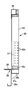
structures and the underframe portion are reinforced, and shock
absorption members are disposed, thereby protecting the cabin
(e.g., refer to Patent Literature 1).
Citation List
Patent Literature
[0003]
Patent Literature 1: Japanese Patent Application Laid-Open No.
2001-48016
1
CA 02798570 2012-11-05
Summary of Invention
Technical Problem
f n n n n l
Luuu'=J
However, when large external force is applied to the side
structures or the end structures due to a collision etc., the side
structures and the end structures may be greatly deformed or
damaged so that the cabin cannot be sufficiently protected.
[0005]
Then, the present invention is intended to provide a railway
vehicle having a configuration which can sufficiently protect the
cabin even when large external force is applied to the side
structure or the end structure.
Solution to Problem
[0006]
In order to achieve the above-mentioned object, the railway
vehicle of the present invention is configured by joining an
underf rame, side structures, end structures, and a roof structure,
so as to form a vehicle body, wherein a lower inner face of a post
member of the side structure or the end structure is joined to
an outer face portion of the underframe.
[0007]
Moreover, in the railway vehicle of the present invention,
the post member is a side post of the side structure which is joined
to a side beam of the underframe, or a post member of the end
structure which is joined to an end beam of the underframe.
2
CA 02798570 2012-11-05
[0008]
The post member is a post reinforcement member for
reinforcing the post member of the end structure which is joined
to the end beam of the underframe. The post reinforcement member
has height which is 1/2 with respect to the height of the post
member of the end structure.
[0009]
A projecting piece is disposed on the outer face side of
the underframe so as to project toward an outside of the vehicle
body. The lower end of the post member is joined to the upper
face portion of the projecting piece.
[0010]
A projecting piece is disposed so as to project from an
intermediate position in the vertical directions on the outer face
side of the underframe toward the outside of the vehicle body.
A slit is disposed in the projecting piece so as to penetrate into
the lower portion of the post member. The lower end portion of
the post member is joined to the outer face portion of the
underframe through the slit.
Advantageous Effects of Invention
[0011]
According to the railway vehicle of the present invention,
because the lower end portions of the post members of the side
structures and the end structures are joined to the outer face
portions of the side beams and the end beams of the underframe,
3
CA 02798570 2012-11-05
the joining strength between the lower ends of the post members
and the side beams or the end beams can be enhanced. Accordingly,
L1-
the _ _ i - _ _ n - l t - _ _ - - applied - t'- _ ~ - L _ _ _ _ - and
1.11C external 1V1C.;C to 1.11C side structure L1C end
structure can be surely born by the underframe through the lower
end portion of the post member, so that deformations of the side
structure and the end structure toward the inside of the vehicle
body can be suppressed.
[0012]
Moreover, a projecting piece projecting toward the outside
of the vehicle body may be disposed on the outer face side of the
underframe, and the lower end of the post member may be joined
to the upper face portion of the projecting piece. Or, the lower
end portion of the post member may be joined to the outer face
portion of the underframe through a slit formed in the projecting
piece. With this, the joining strength therebetween can be
further enhanced, and the external force applied from above to
the post member can be also born by the underframe.
Brief Description of Drawings
[0013]
FIG. 1 is a side view of a vehicle structure illustrating
an embodiment of the present invention.
FIG. 2 is a II-II cross-sectional view of FIG. 1.
FIG. 3 is an explanatory diagram of a main portion
illustrating a joining state between a side post and an underframe .
FIG. 4 is a IV-IV cross-sectional view of FIG. 3.
4
CA 02798570 2012-11-05
FIG. 5 is a front view of the vehicle structure.
FIG. 6 is a VI-VI cross-sectional view of FIG. 5.
FIG. 7 is a VII-VII cross-sectional view of FIG. 5.
FIG. 8 is a VIII-VIII cross-sectional view of FIG. 5.
FIG. 9 is an explanatory diagram illustrating a state of
assembling between an end post and a post reinforcement member,
and between a corner post and a post reinforcement member.
FIG. 10 is a front view of the underframe of the vehicle
structure.
FIG. 11 is a XI-XI cross-sectional view of FIG. 10.
FIG. 12 is a XII-XII cross-sectional view of FIG. 10.
FIG. 13 is a side view of a main portion of the vehicle
structure.
FIG. 14 is a XIV-XIV cross-sectional view of FIG. 13.
FIG. 15 is a XV-XV cross-sectional view of FIG. 13.
FIG. 16 is a XVI-XVI cross-sectional view of FIG. 13.
FIG. 17 is a cross-sectional view of a main portion of a
lower slide portion.
FIG. 18 is a perspective view of a shock absorption member.
FIG. 19 is a side view of a railway vehicle.
FIG. 20 is a front view of the railway vehicle.
Description of Embodiment
[0014]
A vehicle body 11 of a railway vehicle as described in the
present embodiment is provided with an underframe 20, a pair of
CA 02798570 2012-11-05
right and left side structures 30 disposed on both sides of the
underframe 20 in the longitudinal directions, end structures 50
disposed on the end portions of the vehicle body 11 Lhr-ough
crushable zones 40, and a roof structure 60 disposed so as to cover
the upper portions of the side structures 30 and the end structures
50. At both front and rear end portions of the side faces of the
vehicle body 11, vestibules 13 having passenger doors 12 are
respectively disposed, and a cabin 14 is disposed between the
vestibules 13 at both ends. A plurality of side window 15 are
disposed on the side walls of the cabin 14, and interior materials
and seats are disposed in the cabin 14.
[0015]
The underframe 20 includes a pair of right and left side
beams 21 disposed in the rail directions, center beams 23 and
transverse beams 24 for reinforcement, and a pair of front and
rear cap beams 22 disposed in the railroad tie directions at both
front and rear end portions of the center beams 23. At the lower
portion of the cap beam 22, a truck provided with wheels 16 is
disposed, and a floor board 17 is disposed at the upper portion
of the underframe 20. The side beam 21 is a member having a
Z-shaped cross-section, and includes a projecting piece 21a which
projects in the horizontal direction toward the outside of the
vehicle body from the lower end portion of the side beam 21.
[0016]
The side structure 30 is provided with a plurality of side
6
CA 02798570 2012-11-05
posts 31 in the vertical directions, a plurality of frame members
32 in the front and back directions of the vehicle body, door frame
portions 33 in which the passenger doors 12 are disposed, window
frame portions 34 in which the side windows 15 are disposed,
wainscot panels 35 disposed at the lower portions of the side
windows 15, skin panels 36 disposed at the upper portions of the
side windows 15, and door pocket portions 37 disposed on the cabin
sides of the door frame portions 33. The lower end of the side
post 31 is joined to the upper face portion of the projecting piece
21a which is disposed at the side beam 21 through a rocker rail
25, and the outer face portion 21b of the side beam 21 is joined
to the lower inner face of the side post 31.
[0017]
The roof structure 60 is formed by a pair of cant rails 61
which are respectively disposed on both sides in the rail
directions, a plurality of rafters 62 in the railroad tie
directions which are orthogonally joined to the cant rails 61,
and a shingle 63 joined to the outside of the rafters 62. Both
ends of the cant rail 61 are joined to the upper portions of the
end structures 50, and both ends of the rafter 62 are joined to
the upper ends of the side structures 30 through the cant rails
61. The shingle 63 is formed so as to have a curved face gently
projecting upward, and instruments, such as a horn 64, are disposed
on the roof as appropriate.
[0018]
7
CA 02798570 2012-11-05
The end structure 50 includes an opening frame portion for
door 51 for a connecting door 18 which is disposed at the center
in the width direction, and U~1Ci11ilt~ frame portions for windows
52 for front face windows (end face windows) 19 which are
respectively disposed on the right and left of the connecting door
18. A pair of end posts (central portion collision posts) 53 are
respectively disposed between the opening frame portion for door
51 and each of the opening frame portions for windows 52 . A pair
of corner posts (end portion collision posts) 54 are respectively
disposed at the outsides of the opening frame portions for windows
52 which are both end portions in the end structure width
directions. At the central portion in the vertical directions
of this corner post 54, a reinforcement member 52a is disposed
in order to enhance the rigidity of the side portion of the end
face window 19. The lower portion of the end structure 50 is
rigidly joined through the end post reinforcement members 57 and
corner post reinforcement members 58 to the end beam 26 disposed
at each of both front and rear ends of the underframe 20 and is
integrally formed therewith. Moreover, at the upper portion of
the end structure 50, an upper reinforcement beam 56 is disposed
in the railroad tie directions under a state of being independent
from the portion joined with the roof structure 60.
[0019]
A sweep-back angle toward the side is formed at the front
face window 19, and the planar view of the outer face (end face)
8
CA 02798570 2012-11-05
of the end structure 50 is formed in a triangle folded end shape
whose connecting door 18 portion projects. The side face upper
half portion of the end structure 50 is inclined toward the inside
of the vehicle body, similar to the side structures 30.
[0020]
The end beam 26 is formed in a Z-shaped cross-section. The
upper face portion thereof toward the inside of the vehicle body
is provided with an upper face plate 55. The distal end of the
lower projecting piece 26a horizontally projecting toward the
outside of the vehicle body is formed in a shape corresponding
to the triangle folded end shape of the end structure 50. With
this, there is no need to perform a process for folding the entire
end beam 26 so as to correspond to the shape of the end structure
50. In addition to this, the end post reinforcement member 57
and the corner post reinforcement member 58 can be rigidly fixed
by welding to the end beam 26 by the projecting piece 26a.
[0021]
At the positions of the end beam 26 corresponding to the
end posts 53, a pair of end post reinforcement members 57 each
having height of about 1/2 of that of the end post 53 are
respectively disposed. At the positions of both end portions of
the end beam 26 corresponding to the corner posts 54, a pair of
corner post reinforcement members 58 each having length reaching
the lower frame portion of the opening frame portion for window
52 are respectively disposed. At the lower portion of the end
9
CA 02798570 2012-11-05
beam 26, a coupler support frame 59a for supporting a coupler 59
is disposed.
[..U.0U22]
The lower portion 57a of the end post reinforcement member
57 is joined to the outer faces of the end beam 26 and the end
beam lower member 26c through the slits 26b which are formed in
the upper face plate 55 and the projecting piece 26a, respectively.
The lower end of the lower portion 58a of the corner post
reinforcement member 58 is joined to the upper face of the
projecting piece 26a, and the side face of the lower end portion
thereof is joined to the outer face of the end beam 26. Thus,
the end post reinforcement member 57 and the corner post
reinforcement member 58 are joined to the outer face of the end
beam 26 so that the end post reinforcement member 57 and the corner
post reinforcement member 58 can be rigidly joined to the end beam
26, and external force applied to the end post reinforcement member
57 and the corner post reinforcement member 58 can be born by the
end beam 26.
[0023]
Moreover, the end post reinforcement member 57 and the end
post 53 are joined to each other, and the corner post reinforcement
member 58 and the corner post 54 are joined to each other, so that
the end post 53 and the corner post 54 can be joined to the
underframe 20 with sufficient joining strength against shearing
force and bending moment caused at the respective joined portions
CA 02798570 2012-11-05
of the end post 53 and the corner post 54 by external force applied
to all vertical positions of the end post 53 and the corner post
54. Moreover, the height of each of the post reinforcement
members 57, 58 is set to the height of about 1/2 of the height
of the end post 53 or the corner post 54 so that loads applied
to all vertical positions of the end post 53 and the corner post
54 can be effectively born, and sufficient joining strength with
the underframe 20 can be held.
[0024]
At the vehicle body inner sides of the end post 53 and the
corner post 54, there are respectively provided openings 53a, 54a
through which the respective post reinforcement members 57, 58
can pass. The end post 53 and the corner post 54 are assembled
with the respective post reinforcement members 57, 58 by inserting
the respective post reinforcement members 57, 58 into the insides
of the end post 53 and the corner post 54 through the openings
53a, 54a of the end post 53 and the corner post 54 which have been
preliminary assembled into the end structure 50. The end post
53 and the corner post 54 are joined to the respective post
reinforcement members 57, 58 by welding the inner circumferences
of a plurality of joining holes 53b, 54b disposed on the side faces
of the end post 53 and the corner post 54 and the side faces of
the respective post reinforcement members 57, 58. Moreover,
reinforcement angle 53c, 54c are joined and connected between the
lower end potions of the end post 53 and the corner post 54 and
11
CA 02798570 2012-11-05
the upper face plate 55.
[0025]
T L i L ~ - i t_ - t _ _1_
At. the upper portions of L11C end post 53 and L1C LULL1er osL
54, the outer sides of the end post 53 and the corner post 54 are
extended upward, and these extended portions are disposed on the
outer face of the upper reinforcement beam 56 so as to be joined
thereto, respectively. Namely, the end beam 26 and the upper
reinforcement beam 56 are connected by the end posts 53 and the
corner posts 54 which are joined to their outer faces, so that
the overall rigidity of the end structure 50 is enhanced by
assembling in a frame the end beam 26, the upper reinforcement
beam 56, a pair of end posts 53, and a pair of corner posts 54.
Moreover, the post reinforcement members 57, 58 are respectively
disposed at the lower portions of the end post 53 and the corner
posts 54, and the lower portions of the respective post
reinforcement members 57, 58 are joined to the outer face of the
end beam 26, so that the rigidity of the end structure 50 is further
enhanced.
[0026]
The thus formed end structure 50 is joined to the end beam
26 and the upper face plate 55 connected to the slide center beam
43, and is disposed at the end portion of the vehicle body 11
through the crushable zone 40 which is disposed at the vestibule
13 portion. At the upper and lower sides of this crushable zone
40, a lower slide portion 41 and an upper slide portion 42 are
12
CA 02798570 2012-11-05
disposed.
[0027]
The lower slide portion 41 is connected to the central
portion in the width directions of the end beam 26. The slide
center beam 43, which is disposed so as to horizontally project
in a substantially T letter-shape in a planar view toward the
direction of the cap beam 22, is disposed so as to be slidable
in the vehicle body front and back directions through support
members 43a, 44a with respect to a guide center beam 44 projecting
horizontally toward the direction of the vehicle end from the cap
beam 22, and is connected by a lower fuse member which is designed
so as to be broken when the load exceeds a preliminary set value.
[0028]
The upper slide portion 42 is provided with slide bars 47
which horizontally project along lintel portions 33a of the door
frame portion 33 from both end portions of the upper reinforcement
beam 56, and guide frames 48 disposed at the upper portions of
the door pocket portions 37. The slide bar 47 is disposed so as
to be slidable in the vehicle body front and back directions with
respect to the guide frame 48, and similar to the lower slide
portion 41, the slide bar 47 and the guide frame 48 are connected
with each other by an upper fuse member which is designed so as
to be broken when the load exceeds a preliminary set value.
[0029]
Each of the fuse members is a member having strength for
13
CA 02798570 2012-11-05
bearing preliminary set tensile load and compressive load. The
strength of the fuse member is set such that the fuse member is
n_i _____Ld____ a_11C11L 1 Ly __ UC -Lr-_... ----'--_ i--- , - , -- 1 --
IIOL
~ICLLLULLLLCU UL 1JLURC1 I L)y L.11C lIULLLLd1 L.Ci1511C 1UdU UL
compressive load which is applied when a plurality of railway
vehicles are used by connecting with one another by the couplers
59, and is broken when an excessive load over the preliminary set
load is applied by a collision. Namely, when the fuse member is
broken due to an application of an excessive load, the slide center
beam 43 and the slide bar 47 become slidable with respect to the
guide center beam 44 and the guide frame 48 so that energy is
absorbed by crushing a plurality of shock absorption members 45
disposed in the underframe 20.
[0030]
The strength of respective members disposed at the vestibule
portion, for example, the strength at the vestibule portions of
the door frame portion 33, the floor board 17, and the roof
structure 60, is set at strength lower than the strength of the
fuse member, such that when the fuse member is broken by an
application of an excessive load, the vestibule portions of the
door frame portion 33, the floor board 17, and the roof structure
60 are deformed at the same time of the break of the fuse member.
[0031]
The shock absorption member 45 can be made by combining,
for example, four long shock absorbers 45a made of square pipes
each having the same shape of square cross-section and two short
14
CA 02798570 2012-11-05
shock absorbers 45b each having a length shorter than the length
of the long shock absorber 45a so as to make the axes of the
respective shock absorbers 45a, 45b parallel with each other. The
proximal end of each of the shock absorbers 45a, 45b is integrally
joined to a mounting plate 45c. The mounting plate 45c is mounted
on the end faces of the cap beam 22 and the guide center beam 44,
and the axes of the respective shock absorbers 45a, 45b are
disposed so as to be oriented in the vehicle body front and back
directions. At the distal end of each of the shock absorbers 45a,
45b, cutout portions 45d are respectively formed in the distal
edges of a set of opposing faces between two sets of opposing faces.
The respective shock absorbers 45a, 45b are combined such that
the respective cutout portions 45d themselves are not adjacent
to each other.
[0032]
Thus formed shock absorber 45 is deformed at the time of
collision first at the opposing edges of the long shock absorber
45a where the cutout portion 45d is not disposed. Subsequently,
the opposing edges of the short shock absorber 45b where the cutout
portion 45d is not disposed start to be deformed by an application
of collision. The deformations of the respective shock absorbers
45a, 45b are continuously repeated toward the proximal end side
while mutually influencing the wall face of adjacent shock
absorber. With this, a shock can be absorbed by continuously
making the wall faces of the respective shock absorbers 45a, 45b
CA 02798570 2012-11-05
buckled into a bellows-like state. Moreover, because a plurality
of shock absorbers are disposed and joined in the width directions
and L1-1e VeLLJ d1 UILtUL.Loi1S, L11e bending 119IUI y of LI1e 5ilocK
absorption member 45 is enhanced so that the intermediate portion
can be prevented from being bent, thereby the collision energy
can be surely absorbed.
[0033]
Thus, the end beam 26, to which the lower portion of the
end structure 50 is joined, is held so as to be slidable in the
vehicle body front and back directions by the lower slide portion
41 which is formed by the slide center beam 43 and the guide center
beam 44. The upper reinforcement beam 56 disposed at the upper
portion of the end structure 50 is held so as to be slidable in
the vehicle body front and back directions by the upper slide
portion 42 which is formed by the slide bar 47 and the guide frame
48 which are disposed on both sides of the vehicle body. The end
beam 26 and the upper reinforcement beam 56 are rigidly connected
with each other by the end post 53 and the corner post 54. Moreover,
at the lower portion of the end post 53 and the corner post 54,
the post reinforcement members 57, 58 are respectively disposed
for enhancing the rigidities of the end post 53 and the corner
post 54. Accordingly, the end beam 26, the upper reinforcement
beam 56, the end post 53, and the corner post 54 are rigidly joined
to one another, and the end post 53 and the corner post 54 are
disposed at the front faces of the end beam 26 and the upper
16
CA 02798570 2012-11-05
reinforcement beam 56, thereby the end structure 50 becomes a state
of being rigidly assembled in a frame.
[0034]
With this, even when large external force is applied from
the front direction to the end structure 50, large external force
is applied from an oblique direction to the end structure 50,
and/or large external force is applied to a part of the end
structure 50, the external force can be born by the entire end
structure 50, and the end structure 50 can be moved parallel to
the vehicle body backward direction by the lower slide portion
41 and the upper slide portion 42, thereby, the end structure 50
is prevented from falling down toward the cabin 14.
[0035]
Moreover, the end post 53 and the corner post 54 are joined
to the upper reinforcement beam 56 and the outer face of the end
beam 26 so that external force applied to the end post 53 and the
corner post 54 can be surely transmitted to the upper reinforcement
beam 56 and the end beam 26. The lower end of the lower portion
of the corner post reinforcement member 58 is joined to the upper
face of the projecting piece 26a, and the side face of the lower
end portion thereof is joined to the outer face of the end beam
26, so that the joining strength between the corner post
reinforcement member 58 and the end beam 26 can be enhanced,
compared with the case in which the corner post reinforcement
member 58 is disposed so as to stand on the upper face of the end
17
CA 02798570 2012-11-05
beam 26. Thereby, external force to the end face can be
effectively transmitted to the entire end structure 50 and the
L ---_
end UCdt1I 26.
[0036]
Therefore, regardless of the application direction of
external force applied to the end structure 50 and the application
position thereof, the end structure 50 can be moved parallel to
the vehicle body backward direction while the vestibule 13 portion,
which is a crushable zone, is being deformed. Therefore, external
force is applied to the shock absorption member 45 in the axial
directions of the respective shock absorbers 45a, 45b. Thereby,
as mentioned above, the respective shock absorbers 45a, 45b can
be surely deformed to be buckled so that the external force
absorbing effect by the shock absorption member 45 can be fully
used. Thus, the cabin 14 can be protected by deforming only the
vestibule 13 portion which is disposed at the vehicle end portion
so as to absorb collision energy.
[0037]
Moreover, the lower end of the side post 31 of the side
structure 30 is joined to the upper face portion of the projecting
piece 21a which is disposed at the side beam 21 of the underframe
20, and the lower inner face of the side post 31 is joined to the
outer face portion 21b of the side beam 21. Thereby, the external
force applied to the side structure 30 from the side of the vehicle
body can be born by the outer face portion 21b of the side beam
18
CA 02798570 2012-11-05
21 through the lower end portion of the side post 31 . Accordingly,
the joining strength between the side post 31 and the side beam
21 can be enhanced, compared with the case in which the lower end
of the side post 31 is joined to the upper face of the side beam
21, and the underframe 20 and the side structure 30 can be rigidly
joined to each other. Thereby, the deformation of the side
structure 30 toward the inside of the vehicle body can be
suppressed even when large external force is applied to the side
face portion of the vehicle body. Moreover, the external force
applied to the roof structure 60 from above can be born by the
projecting piece 21a of the side beam 21 through the side post
31, so that the deformation of the roof structure 60 toward the
inside of the vehicle body by external force from above can be
suppressed.
[0038]
The end post 53 and the corner post 54 are assembled with
the respective post reinforcement members 57, 58 by inserting the
respective post reinforcement members 57, 58 into the insides of
the end post 53 and the corner post 54 through the openings 53a,
54a which are formed at the vehicle body inner sides of the end
post 53 and the corner post 54, so that the end structure 50 can
be assembled by moving the same in the horizontal direction. With
this, the end structure 50 and the underframe 20 can be combined
under a state in which the end post 53 and the corner post 54 are
preliminary assembled into the end structure 50 which can have
19
CA 02798570 2012-11-05
various vehicle body cross-sections, so that the respective post
reinforcement members 57, 58 can be easily assembled with the end
post 53 and the corner post 54. MMloreover, all end strucUULe whose
end post 53 and corner post 54 are inclined can be addressed.
[0039]
Note that, at the front head portion of the vehicle body,
a driver's cab and a crew's room are disposed at the vestibule
13 portion, and a hood and a marker light, etc. are disposed at
the end face. The end post 53 can be disposed at a suitable
position according to the existence or non-existence of the
connection door 18 or the shape of the end face window 19, and
can be single. Moreover, suitable configurations can be adopted
for the configuration of the shock absorption member 45 and the
configurations of the respective connection members 46 and the
upper connection member 49.
Reference Signs List
[0040]
11... vehicle body, 12... passenger door, 13... vestibule, 14... cabin,
15... side window, 16... wheel, 17... floor board, 18... connecting door,
19... end face window, 20... underframe, 21... side beam, 21a... projecting
piece, 21b... outer face portion, 22... cap beam, 23... center beam,
24... transverse beam, 25... rocker rail, 26... endbeam, 26a...projecting
piece, 26b... slit, 30... side structure, 31... side post, 32... frame
member, 33... door frame portion, 33a... lintel portion, 34... window
frame portion, 35... wainscot panel, 36... skin panel, 37... door pocket
CA 02798570 2012-11-05
portion, 40... crushable zone, 41... lower slide portion, 42... upper
slide portion, 43... slide center beam, 44... guide center beam, 45...
shock absorption member, 45a... long shock absorber, 45b... short
shock absorber, 45c... mounting plate, 45d... cutout portion, 47...
slide bar, 48... guide frame, 50... end structure, 51... opening frame
portion for door, 52... opening frame portion for window, 52a...
reinforcement member, 53... end post, 54... corner post, 53a, 54a...
opening, 53b, 54b... joining hole, 53c, 54c... reinforcement angle,
55... upper face plate, 56... upper reinforcement beam, 57... end post
reinforcement member, 58... corner post reinforcement member, 59...
coupler, 59a... coupler support frame, 60... roof structure, 61... cant
rail, 62... rafter, 63... shingle, 64... horn
21