Note: Descriptions are shown in the official language in which they were submitted.
CA 02798632 2012-11-06
WO 2011/140468 PCT/US2011/035564
PROCESS FOR PRODUCING ETHANOL BY HYDROGENATION OF ACETIC ACID
PRIORITY CLAIM
[0001] This application claims priority to U.S. App. No. 13/078,727, filed on
April 1, 201.1,
and U.S. Provisional App. No. 61/332,696, filed on May 7, 2010, the entire
content and
disclosure of which is incorporated herein by reference.
FIELD OF THE INVENTION
[0002] The present invention relates generally to processes for producing
and/or purifying
ethanol and, in particular, to processes for controlling non-condensable gas
from the
hydrogenation of acetic acid.
BACKGROUND OF THE INVENTION
[0003] Ethanol for industrial use is conventionally produced from
petrochemical feed stocks,
such as oil, natural gas, or coal, from feed stock intermediates, such as
syngas, or from starchy
materials or cellulose materials, such as corn or sugar cane. Conventional
methods for producing
ethanol from petrochemical feed stocks, as well as from cellulose materials,
include the acid-
catalyzed hydration of ethylene, methanol homologation, direct alcohol
synthesis, and Fischer-
Tropsch synthesis. Instability in petrochemical feed stock prices contributes
to fluctuations in
the cost of conventionally produced ethanol, making the need for alternative
sources of ethanol
production all the greater when feed stock prices rise. Starchy materials, as
well as cellulose
material, are converted to ethanol by fermentation. However, fermentation is
typically used for
consumer production of ethanol. In addition, fermentation of starchy or
cellulose materials
competes with food sources and places restraints on the amount of ethanol that
can be produced
for industrial use.
[0004] Ethanol production via the reduction of alkanoic acids and/or other
carbonyl group-
containing compounds has been widely studied, and a variety of combinations of
catalysts,
supports, and operating conditions have been mentioned in the literature.
During the reduction
of alkanoic acid, e.g., acetic acid, other compounds are formed with ethanol
or are formed in side
reactions. These impurities limit the production and recovery of ethanol from
such reaction
mixtures. For example, during hydrogenation, esters are produced that together
with ethanol
1
CA 02798632 2012-11-06
WO 2011/140468 PCT/US2011/035564
and/or water form azeotropes, which are difficult to separate. In addition
when conversion is
incomplete, unreacted acid remains in the crude ethanol product, which must be
removed to
recover ethanol.
[0005] Excess of hydrogen is used to increase the yield of ethanol production
in converting
carbonaceous feedstock into low-molecular weight alcohols. Due to the use of
excess amounts
of hydrogen, it is beneficial to recycle the unreacted hydrogen back to the
reactor. However,
additional gases are also formed during the reaction, such as methane, ethane,
nitrogen, carbon
monoxide, and carbon dioxide, that would build-up reactor when hydrogen is
recycled.
EP2060555 describes purging the gas recycle stream to control the build up of
the gases in the
hydrogenation reactor. Purging the gas recycle stream results in the lost of
the reactants for the
reaction and reduces operating efficiencies.
[0006] However, a need remains for improving the processes for controlling non-
condensable
gas from the hydrogenation of acetic acid to increase production of ethanol.
SUMMARY OF THE INVENTION
[0007] In a first embodiment, the present invention is directed to a process
for producing
ethanol, comprising hydrogenating acetic acid from an acetic acid feed stream
in a reactor in the
presence of a catalyst to form a crude ethanol product comprising ethanol;
separating at least a
portion of the crude ethanol product to yield a vapor stream and a liquid
stream, wherein the
vapor stream comprises unreacted hydrogen and at least one by-product gas, and
wherein the
liquid stream comprises ethanol; purging less than 15% of the vapor stream in
a first purge
stream; returning at least a portion of the vapor stream directly or
indirectly to the reactor; and
recovering ethanol from the liquid stream.
[0008] In a second embodiment, the present invention is directed to a process
for producing
ethanol comprising hydrogenating acetic acid from an acetic acid feed stream
in a reactor in the
presence of a catalyst to form a crude ethanol product comprising ethanol;
separating at least a
portion of the crude ethanol product to yield a vapor stream and a liquid
stream, wherein the
vapor stream comprises unreacted hydrogen and carbon monoxide in an amount
less than 2
mol.%, and wherein the liquid stream comprises ethanol; returning at least a
portion of the vapor
stream directly or indirectly to the reactor; and recovering ethanol from the
liquid stream.
2
CA 02798632 2012-11-06
WO 2011/140468 PCT/US2011/035564
[0009] In a third embodiment, the present invention is directed to a process
for producing
ethanol comprising hydrogenating acetic acid from an acetic acid feed stream
and a hydrogen
feed stream in a reactor system in the presence of a catalyst to form a crude
ethanol product
comprising ethanol; separating at least a portion of the crude ethanol product
to yield a vapor
stream and a liquid stream, wherein the vapor stream comprises unreacted
hydrogen, and
wherein the liquid stream comprises ethanol; returning at least a portion of
the vapor stream
directly or indirectly to the reactor; measuring a pressure of the vapor
stream or a pressure of the
at least a portion of the vapor stream; controlling pressure in the reactor
system by regulating the
feed of fresh hydrogen to the reactor in response to the measured pressure;
and recovering
ethanol from the liquid stream.
[0010] In a fourth embodiment, the present invention is directed to a process
for producing
ethanol comprising hydrogenating acetic acid from an acetic acid feed stream
in a reactor in the
presence of a catalyst to form a crude ethanol product comprising ethanol;
separating the crude
ethanol product to yield a vapor stream and a liquid stream, wherein the vapor
stream comprises
unreacted hydrogen and at least one by-product gas, and wherein the liquid
stream comprises
ethanol; withdrawing a slip stream from the vapor stream; purging a portion of
the slip stream
when the concentration of one of the at least one by-product gases is greater
than 5 mol.%; and
recovering ethanol from the liquid stream.
[0011] In a fifth embodiment, the present invention is directed to a process
for producing
ethanol comprising hydrogenating acetic acid from an acetic acid feed stream
in a reactor in the
presence of a catalyst to form a crude ethanol product comprising ethanol;
separating at least a
portion of the crude ethanol product to yield a vapor stream and a liquid
stream, wherein the
vapor stream comprises unreacted hydrogen and at least one by-product gas, and
wherein the
liquid stream comprises ethanol and at least one dissolved by-product gas;
purging the at least
one dissolved by-product gas from the liquid stream; and recovering ethanol
from the liquid
stream.
BRIEF DESCRIPTION OF DRAWINGS
[0012] The invention is described in detail below with reference to the
appended drawings,
wherein like numerals designate similar parts.
[0013] FIG. 1 is a schematic diagram of the reaction zone in accordance with
one embodiment
3
CA 02798632 2012-11-06
WO 2011/140468 PCT/US2011/035564
of the present invention.
[0014] FIG. 2 is a schematic diagram of the reaction zone in accordance with
one embodiment
of the present invention.
[0015] FIG. 3 is a schematic diagram of the reaction zone in accordance with
one embodiment
of the present invention.
[0016] FIG. 4 is a schematic diagram of the reaction zone and recycling of gas
in accordance
with one embodiment of the present invention.
[0017] FIG. 5 is a schematic diagram of a hydrogenation system in accordance
with one
embodiment of the present invention.
[0018] FIG. 6 is a graph showing the build up of gaseous by-products over a 24-
hour period in
the recycle loop of hydrogenation process.
[0019] FIG. 7 is a graph showing the build up of gaseous by-products over a 3-
day period at
300 C in the recycle loop of hydrogenation process.
[0020] FIG. 8 is a graph showing the build up of gaseous by-products over a 3-
day period at
250 C in the recycle loop of hydrogenation process.
[0021] FIG. 9 is a graph showing the build up of gaseous by-products over a 3-
day period at
275 C in the recycle loop of hydrogenation process.
DETAILED DESCRIPTION OF THE INVENTION
[0022] The present invention relates to processes for recovering ethanol
produced by a
hydrogenation process comprising hydrogenating acetic acid in the presence of
a catalyst. In
particular, the present invention relates to recovering and/or purifying
ethanol from a crude
ethanol product preferably produced by the hydrogenation process. The process
includes a step
of recycling unreacted hydrogen gas in a recycled vapor stream from the crude
reaction mixture
by returning it to the reaction process, preferably to the reactor. The
returned hydrogen may be
reacted under hydrogenation conditions to make additional ethanol. In one
embodiment,
portions of the unreacted hydrogen and the non-condensable gaseous byproducts
are purged from
the crude ethanol product and the lost volume may be replaced by fresh
hydrogen gas. This may
dilute harmful gaseous by-products in the recycled vapor stream for the
hydrogenation process.
In another embodiment, the system pressure may be maintained at a steady level
by controlling
the fresh hydrogen level, such that fresh hydrogen may be added to replenish
the hydrogen
4
CA 02798632 2012-11-06
WO 2011/140468 PCT/US2011/035564
consumed during the hydrogenation process or to replace the volume of the
purged gas.
Embodiments of the present invention beneficially may be used in applications
for recovering
and/or purifying ethanol on an industrial scale.
[0023] The hydrogenation of acetic acid forms equal molar ratios of ethanol
and water.
Although the reaction consumes two moles of hydrogen per mole of acetic acid
to produce one
mole of ethanol, the actual molar ratio of hydrogen to acetic acid in the feed
stream may vary
from about 100:1 to 1:100, e.g., from 50:1 to 1:50, from 20:1 to 1:2, or from
12:1 to 1:1. Most
preferably, the molar ratio of hydrogen to acetic acid is greater than 2:1,
e.g., greater than 4:1 or
greater than 8:1.
[0024] When excess of hydrogen is used, thermal decomposition of acetic acid,
water-gas shift
reaction and ethanol dehydration occur and form undesirable by-products, such
as methane,
ethane, carbon monoxide and carbon dioxide (Formulas I-IV):
[0025] CH3COOH -* CH4 + CO2 I
[0026] CO2 + H2 H CO + H2O II
[0027] CH3CH2OH -* CH2=CH2 + H2O III
[0028] CH2=CH2 + H2 - CH3CH3 IV
[0029] The by-product gases may be harmful to certain types of hydrogenation
catalysts and
may lead to the formation of further impurities in the ethanol.
Conventionally, it is understood to
purge the gas recycle line to remove the by-product gases. Surprisingly and
unexpectedly, the
inventors have found that the levels of by-product gases in the reactor reach
a steady state when
the gas recycle line is recycled without a purge. Without being bound by
theory, the by-product
gases are dissolved in the liquid phase and may be vented after separation in
one or more
columns. Thus, hydrogen may be effectively recycled while by-product gases may
be removed
from the process. In addition, a smaller purge may be used to remove by-
product gases from the
gas recycle line.
[0030] The process of the present invention may be used with any ethanol
production,
preferably with ethanol produced by acetic acid hydrogenation. The materials,
catalyst, reaction
conditions, and separation are described further below.
[0031] The raw materials, acetic acid and hydrogen, used in connection with
the process of this
invention may be derived from any suitable source including natural gas,
petroleum, coal,
biomass, and so forth. As examples, acetic acid may be produced via methanol
carbonylation,
CA 02798632 2012-11-06
WO 2011/140468 PCT/US2011/035564
acetaldehyde oxidation, ethylene oxidation, oxidative fermentation, and
anaerobic fermentation.
Methanol carbonylation processes suitable for production of acetic acid are
described in U.S. Pat.
Nos. 7,208,624; 7,115,772; 7,005,541; 6,657,078; 6,627,770; 6,143,930;
5,599,976; 5,144,068;
5,026,908; 5,001,259 and 4,994,608, the entire disclosures of which are
incorporated herein by
reference. Optionally, the production of ethanol may be integrated with such
methanol
carbonylation processes.
[0032] As petroleum and natural gas prices fluctuate becoming either more or
less expensive,
methods for producing acetic acid and intermediates such as methanol and
carbon monoxide
from alternate carbon sources have drawn increasing interest. In particular,
when petroleum is
relatively expensive, it may become advantageous to produce acetic acid from
synthesis gas
("syngas") that is derived from more available carbon sources. U.S. Patent No.
6,232,352, the
entirety of which is incorporated herein by reference, for example, teaches a
method of
retrofitting a methanol plant for the manufacture of acetic acid. By
retrofitting a methanol plant,
the large capital costs associated with CO generation for a new acetic acid
plant are significantly
reduced or largely eliminated. All or part of the syngas is diverted from the
methanol synthesis
loop and supplied to a separator unit to recover CO, which is then used to
produce acetic acid. In
a similar manner, hydrogen for the hydrogenation step may be supplied from
syngas.
[0033] In some embodiments, some or all of the raw materials for the above-
described acetic
acid hydrogenation process may be derived partially or entirely from syngas.
For example, the
acetic acid may be formed from methanol and carbon monoxide, both of which may
be derived
from syngas. The syngas may be formed by partial oxidation reforming or steam
reforming, and
the carbon monoxide may be separated from syngas. Similarly, hydrogen that is
used in the step
of hydrogenating the acetic acid to form the crude ethanol product may be
separated from
syngas. The syngas, in turn, may be derived from variety of carbon sources.
The carbon source,
for example, may be selected from the group consisting of natural gas, oil,
petroleum, coal,
biomass, and combinations thereof. Syngas or hydrogen may also be obtained
from bio-derived
methane gas, such as bio-derived methane gas produced by landfills or
agricultural waste.
[0034] In another embodiment, the acetic acid used in the hydrogenation step
may be formed
from the fermentation of biomass. The fermentation process preferably utilizes
an acetogenic
process or a homoacetogenic microorganism to ferment sugars to acetic acid
producing little, if
any, carbon dioxide as a by-product. The carbon efficiency for the
fermentation process
6
CA 02798632 2012-11-06
WO 2011/140468 PCT/US2011/035564
preferably is greater than 70%, greater than 80% or greater than 90% as
compared to
conventional yeast processing, which typically has a carbon efficiency of
about 67%.
Optionally, the microorganism employed in the fermentation process is of a
genus selected from
the group consisting of Clostridium, Lactobacillus, Moorella,
Thermoanaerobacter,
Propionibacterium, Propionispera, Anaerobiospirillum, and Bacteriodes, and in
particular,
species selected from the group consisting of Clostridium formicoaceticum,
Clostridium
butyricum, Moorella thermoacetica, Thermoanaerobacter kivui, Lactobacillus
delbrukii,
Propionibacterium acidipropionici, Propionispera arboris, Anaerobiospirillum
succinicproducens, Bacteriodes amylophilus and Bacteriodes ruminicola.
Optionally in this
process, all or a portion of the unfermented residue from the biomass, e.g.,
lignans, may be
gasified to form hydrogen that may be used in the hydrogenation step of the
present invention.
Exemplary fermentation processes for forming acetic acid are disclosed in US
Pat. Nos.
6,509,180; 6,927,048; 7,074,603; 7,507,562; 7,351,559; 7,601,865; 7,682,812;
and 7,888,082,
the entireties of which are incorporated herein by reference. See also U.S.
Pub. Nos.
2008/0193989 and 2009/0281354, the entireties of which are incorporated herein
by reference.
[0035] Examples of biomass include, but are not limited to, agricultural
wastes, forest
products, grasses, and other cellulosic material, timber harvesting residues,
softwood chips,
hardwood chips, tree branches, tree stumps, leaves, bark, sawdust, off-spec
paper pulp, corn,
corn stover, wheat straw, rice straw, sugarcane bagasse, switchgrass,
miscanthus, animal manure,
municipal garbage, municipal sewage, commercial waste, grape pumice, almond
shells, pecan
shells, coconut shells, coffee grounds, grass pellets, hay pellets, wood
pellets, cardboard, paper,
plastic, and cloth. See, e.g., U.S. Pat. No. 7,884,253, the entirety of which
is incorporated herein
by reference. Another biomass source is black liquor, a thick, dark liquid
that is a byproduct of
the Kraft process for transforming wood into pulp, which is then dried to make
paper. Black
liquor is an aqueous solution of lignin residues, hemicellulose, and inorganic
chemicals.
[0036] U.S. Pat. No. RE 35,377, also incorporated herein by reference,
provides a method for
the production of methanol by conversion of carbonaceous materials such as
oil, coal, natural gas
and biomass materials. The process includes hydrogasification of solid and/or
liquid
carbonaceous materials to obtain a process gas which is steam pyrolized with
additional natural
gas to form synthesis gas. The syngas is converted to methanol which may be
carbonylated to
acetic acid. The method likewise produces hydrogen which may be used in
connection with this
7
CA 02798632 2012-11-06
WO 2011/140468 PCT/US2011/035564
invention as noted above. U.S. Pat. No. 5,821,111, which discloses a process
for converting
waste biomass through gasification into synthesis gas, and U.S. Pat. No.
6,685,754, which
discloses a method for the production of a hydrogen-containing gas
composition, such as a
synthesis gas including hydrogen and carbon monoxide, are incorporated herein
by reference in
their entireties.
[0037] The acetic acid fed to the hydrogenation reaction may also comprise
other carboxylic
acids and anhydrides, as well as acetaldehyde and acetone. Preferably, a
suitable acetic acid feed
stream comprises one or more of the compounds selected from the group
consisting of acetic
acid, acetic anhydride, acetaldehyde, ethyl acetate, and mixtures thereof.
These other
compounds may also be hydrogenated in the processes of the present invention.
In some
embodiments, the presence of carboxylic acids, such as propanoic acid or its
anhydride, may be
beneficial in producing propanol. Water may also be present in the acetic acid
feed.
[0038] Alternatively, acetic acid in vapor form may be taken directly as crude
product from the
flash vessel of a methanol carbonylation unit of the class described in U.S.
Patent No. 6,657,078,
the entirety of which is incorporated herein by reference. The crude vapor
product, for example,
may be fed directly to the ethanol synthesis reaction zones of the present
invention without the
need for condensing the acetic acid and light ends or removing water, saving
overall processing
costs.
[0039] The acetic acid may be vaporized at the reaction temperature, following
which the
vaporized acetic acid can be fed along with hydrogen in an undiluted state or
diluted with a
relatively inert carrier gas, such as nitrogen, argon, helium, carbon dioxide
and the like. For
reactions run in the vapor phase, the temperature should be controlled in the
system such that it
does not fall below the dew point of acetic acid. In one embodiment, the
acetic acid may be
vaporized at the boiling point of acetic acid at the particular pressure, and
then the vaporized
acetic acid may be further heated to the reactor inlet temperature. In another
embodiment, the
acetic acid is transferred to the vapor state by passing hydrogen, recycle
gas, another suitable
gas, or mixtures thereof through the acetic acid at a temperature below the
boiling point of acetic
acid, thereby humidifying the carrier gas with acetic acid vapors, followed by
heating the mixed
vapors up to the reactor inlet temperature. Preferably, the acetic acid is
transferred to the vapor
state by passing hydrogen and/or recycle gas through the acetic acid at a
temperature at or below
125 C, followed by heating of the combined gaseous stream to the reactor inlet
temperature.
8
CA 02798632 2012-11-06
WO 2011/140468 PCT/US2011/035564
[0040] Some embodiments of the process of hydrogenating acetic acid to form
ethanol may
include a variety of configurations using a fixed bed reactor or a fluidized
bed reactor. In many
embodiments of the present invention, an "adiabatic" reactor can be used; that
is, there is little or
no need for internal plumbing through the reaction zone to add or remove heat.
In other
embodiments, a radial flow reactor or reactors may be employed, or a series of
reactors may be
employed with or with out heat exchange, quenching, or introduction of
additional feed material.
Alternatively, a shell and tube reactor provided with a heat transfer medium
may be used. In
many cases, the reaction zone may be housed in a single vessel or in a series
of vessels with heat
exchangers therebetween.
[0041] In preferred embodiments, the catalyst is employed in a fixed bed
reactor, e.g., in the
shape of a pipe or tube, where the reactants, typically in the vapor form, are
passed over or
through the catalyst. Other reactors, such as fluid or ebullient bed reactors,
can be employed. In
some instances, the hydrogenation catalysts may be used in conjunction with an
inert material to
regulate the pressure drop of the reactant stream through the catalyst bed and
the contact time of
the reactant compounds with the catalyst particles.
[0042] The hydrogenation reaction may be carried out in either the liquid
phase or vapor phase.
Preferably, the reaction is carried out in the vapor phase under the following
conditions. The
reaction temperature may range from 125 C to 350 C, e.g., from 200 C to 325 C,
from 225 C to
300 C, or from 250 C to 300 C. The pressure may range from 10 kPa to 3000 kPa,
e.g., from 50
kPa to 2300 kPa, or from 100 kPa to 1500 kPa. The reactants may be fed to the
reactor at a gas
hourly space velocity (GHSV) of greater than 500 hr 1, e.g., greater than 1000
hr 1, greater than
2500 hr i or even greater than 5000 hr 1. In terms of ranges the GHSV may
range from 50 hr -1 to
50,000 hr 1, e.g., from 500 hr -1 to 30,000 hr-1, from 1000 hr -1 to 10,000 hr
1, or from 1000 hr -1 to
6500 hr-1.
[0043] The hydrogenation optionally is carried out at a pressure just
sufficient to overcome the
pressure drop across the catalytic bed at the GHSV selected, although there is
no bar to the use of
higher pressures, it being understood that considerable pressure drop through
the reactor bed may
be experienced at high space velocities, e.g., 5000 hr -1 or 6,500 hr 1.
[0044] Although the reaction consumes two moles of hydrogen per mole of acetic
acid to
produce one mole of ethanol, the actual molar ratio of hydrogen to acetic acid
in the feed stream
may vary from about 100:1 to 1:100, e.g., from 50:1 to 1:50, from 20:1 to 1:2,
or from 12:1 to
9
CA 02798632 2012-11-06
WO 2011/140468 PCT/US2011/035564
1:1. Most preferably, the molar ratio of hydrogen to acetic acid is greater
than 2:1, e.g., greater
than 4:1 or greater than 8:1.
[0045] Contact or residence time can also vary widely, depending upon such
variables as
amount of acetic acid, catalyst, reactor, temperature and pressure. Typical
contact times range
from a fraction of a second to more than several hours when a catalyst system
other than a fixed
bed is used, with preferred contact times, at least for vapor phase reactions,
of from 0.1 to 100
seconds, e.g., from 0.3 to 80 seconds or from 0.4 to 30 seconds.
[0046] The hydrogenation of acetic acid to form ethanol is preferably
conducted in the
presence of a hydrogenation catalyst. Suitable hydrogenation catalysts include
catalysts
comprising a first metal and optionally one or more of a second metal, a third
metal or any
number of additional metals, optionally on a catalyst support. The first and
optional second and
third metals may be selected from Group IB, IIB, IIIB, IVB, VB, VIB, VIIB,
VIII transition
metals, a lanthanide metal, an actinide metal, or a metal selected from any of
Groups IIIA, IVA,
VA, and VIA. Preferred metal combinations for some exemplary catalyst
compositions include
platinum/tin, platinum/ruthenium, platinum/rhenium, palladium/ruthenium,
palladium/rhenium,
cobalt/palladium, cobalt/platinum, cobalt/chromium, cobalt/ruthenium,
cobalt/tin,
silver/palladium, copper/palladium, copper/zinc, nickel/palladium,
gold/palladium,
ruthenium/rhenium, and ruthenium/iron. Exemplary catalysts are further
described in U.S. Pat.
Nos. 7,608,744 and 7,863,489 and U.S. Pub. No. 2010/0197485, the entireties of
which are
incorporated herein by reference. In another embodiment, the catalyst
comprises a Co/Mo/S
catalyst of the type described in U.S. Pub. No. 2009/0069609, the entirety of
which is
incorporated herein by reference.
[0047] In one embodiment, the catalyst comprises a first metal selected from
the group
consisting of copper, iron, cobalt, nickel, ruthenium, rhodium, palladium,
osmium, iridium,
platinum, titanium, zinc, chromium, rhenium, molybdenum, and tungsten.
Preferably, the first
metal is selected from the group consisting of platinum, palladium, cobalt,
nickel, and ruthenium.
More preferably, the first metal is selected from platinum and palladium. In
embodiments of the
invention where the first metal comprises platinum, it is preferred that the
catalyst comprises
platinum in an amount less than 5 wt.%, e.g., less than 3 wt.% or less than 1
wt.%, due to the
high commercial demand for platinum.
CA 02798632 2012-11-06
WO 2011/140468 PCT/US2011/035564
[0048] As indicated above, in some embodiments, the catalyst further comprises
a second
metal, which typically would function as a promoter. If present, the second
metal preferably is
selected from the group consisting of copper, molybdenum, tin, chromium, iron,
cobalt,
vanadium, tungsten, palladium, platinum, lanthanum, cerium, manganese,
ruthenium, rhenium,
gold, and nickel. More preferably, the second metal is selected from the group
consisting of
copper, tin, cobalt, rhenium, and nickel. Most preferably, the second metal is
selected from tin
and rhenium.
[0049] In certain embodiments where the catalyst includes two or more metals,
e.g., a first
metal and a second metal, the first metal is present in the catalyst in an
amount from 0.1 to 10
wt.%, e.g., from 0.1 to 5 wt.%, or from 0.1 to 3 wt.%. The second metal
preferably is present in
an amount from 0.1 to 20 wt.%, e.g., from 0.1 to 10 wt.%, or from 0.1 to 5
wt.%. For catalysts
comprising two or more metals, the two or more metals may be alloyed with one
another, or may
comprise a non-alloyed metal solution or mixture.
[0050] The preferred metal ratios may vary depending on the metals used in the
catalyst. In
some exemplary embodiments, the mole ratio of the first metal to the second
metal is from 10:1
to 1:10, e.g., from 4:1 to 1:4, from 2:1 to 1:2, from 1.5:1 to 1:1.5 or from
1.1:1 to 1:1.1.
[0051] The catalyst may also comprise a third metal selected from any of the
metals listed
above in connection with the first or second metal, so long as the third metal
is different from
both the first and second metals. In preferred embodiments, the third metal is
selected from the
group consisting of cobalt, palladium, ruthenium, copper, zinc, platinum, tin,
and rhenium. More
preferably, the third metal is selected from cobalt, palladium, and ruthenium.
When present, the
total weight of the third metal is preferably from 0.05 to 4 wt.%, e.g., from
0.1 to 3 wt.%, or
from 0.1 to 2 wt.%.
[0052] In addition to one or more metals, in some embodiments of the present
invention, the
catalysts further comprise a support or a modified support. As used herein,
the term "modified
support" refers to a support that includes a support material and a support
modifier, which
adjusts the acidity of the support material.
[0053] The total weight of the support or modified support, based on the total
weight of the
catalyst, preferably is from 75 to 99.9 wt.%, e.g., from 78 to 97 wt.%, or
from 80 to 95 wt.%. In
preferred embodiments that utilize a modified support, the support modifier is
present in an
amount from 0.1 to 50 wt.%, e.g., from 0.2 to 25 wt.%, from 0.5 to 15 wt.%, or
from 1 to 8 wt.%,
11
CA 02798632 2012-11-06
WO 2011/140468 PCT/US2011/035564
based on the total weight of the catalyst. The metals of the catalysts may be
dispersed
throughout the support, layered throughout the support, coated on the outer
surface of the support
(i.e., egg shell), or decorated on the surface of the support.
[0054] As will be appreciated by those of ordinary skill in the art, support
materials are
selected such that the catalyst system is suitably active, selective and
robust under the process
conditions employed for the formation of ethanol.
[0055] Suitable support materials may include, for example, stable metal oxide-
based supports
or ceramic-based supports. Preferred supports include silicaceous supports,
such as silica,
silica/alumina, a Group IIA silicate such as calcium metasilicate, pyrogenic
silica, high purity
silica, and mixtures thereof. Other supports may include, but are not limited
to, iron oxide,
alumina, titania, zirconia, magnesium oxide, carbon, graphite, high surface
area graphitized
carbon, activated carbons, and mixtures thereof.
[0056] As indicated, the catalyst support may be modified with a support
modifier. In some
embodiments, the support modifier may be an acidic modifier that increases the
acidity of the
catalyst. Suitable acidic support modifiers may be selected from the group
consisting of: oxides
of Group IVB metals, oxides of Group VB metals, oxides of Group VIB metals,
oxides of Group
VIIB metals, oxides of Group VIIIB metals, aluminum oxides, and mixtures
thereof. Acidic
support modifiers include those selected from the group consisting of Ti02,
Zr02, Nb205, Ta205,
A1203, B203, P205, and Sb203. Preferred acidic support modifiers include those
selected from
the group consisting of Ti02, Zr02, Nb205, Ta205, and A1203. The acidic
modifier may also
include W03, M0O3, Fe203, Cr203, V205, Mn02, CuO, Co203, or Bi203.
[0057] In another embodiment, the support modifier may be a basic modifier
that has a low
volatility or no volatility. Such basic modifiers, for example, may be
selected from the group
consisting of: (i) alkaline earth oxides, (ii) alkali metal oxides, (iii)
alkaline earth metal
metasilicates, (iv) alkali metal metasilicates, (v) Group IIB metal oxides,
(vi) Group IIB metal
metasilicates, (vii) Group IIIB metal oxides, (viii) Group IIIB metal
metasilicates, and mixtures
thereof. In addition to oxides and metasilicates, other types of modifiers
including nitrates,
nitrites, acetates, and lactates may be used. The basic support modifier may
be selected from the
group consisting of oxides and metasilicates of any of sodium, potassium,
magnesium, calcium,
scandium, yttrium, and zinc, as well as mixtures of any of the foregoing. More
preferably, the
basic support modifier is a calcium silicate, and even more preferably calcium
metasilicate
12
CA 02798632 2012-11-06
WO 2011/140468 PCT/US2011/035564
(CaSiO3). If the basic support modifier comprises calcium metasilicate, it is
preferred that at
least a portion of the calcium metasilicate is in crystalline form.
[0058] A preferred silica support material is SS61138 High Surface Area (HSA)
Silica Catalyst
Carrier from Saint Gobain NorPro. The Saint-Gobain NorPro SS61138 silica
exhibits the
following properties: contains approximately 95 wt.% high surface area silica;
surface area of
about 250 m2/g; median pore diameter of about 12 nm; average pore volume of
about 1.0 cm3/g
as measured by mercury intrusion porosimetry; and packing density of about
0.352 g/cm3 (22
lb/ft).
[0059] A preferred silica/alumina support material is KA-160 silica spheres
from Sud-Chemie
having a nominal diameter of about 5 mm, a density of about 0.562 g/ml, an
absorptivity of
about 0.583 g H20/g support, a surface area of about 160 to 175 m2/g, and a
pore volume of
about 0.68 mug.
[0060] The catalyst compositions suitable for use with the present invention
preferably are
formed through metal impregnation of the modified support, although other
processes such as
chemical vapor deposition may also be employed. Such impregnation techniques
are described
in U.S. Pat. Nos. 7,608,744 and 7,863,489 and U.S. Pub. No. 2010/0197485
referred to above,
the entireties of which are incorporated herein by reference.
[0061] In particular, the hydrogenation of acetic acid may achieve favorable
conversion of
acetic acid and favorable selectivity and productivity to ethanol. For
purposes of the present
invention, the term "conversion" refers to the amount of acetic acid in the
feed that is converted
to a compound other than acetic acid. Conversion is expressed as a mole
percentage based on
acetic acid in the feed. The conversion may be at least 10%, e.g., at least
20%, at least 40%, at
least 50%, at least 60%, at least 70% or at least 80%. Although catalysts that
have high
conversions are desirable, such as at least 80% or at least 90%, in some
embodiments, a low
conversion may be acceptable at high selectivity for ethanol. It is, of
course, well understood
that in many cases, it is possible to compensate for conversion by appropriate
recycle streams or
use of larger reactors, but it is more difficult to compensate for poor
selectivity.
[0062] Selectivity is expressed as a mole percent based on converted acetic
acid. It should be
understood that each compound converted from acetic acid has an independent
selectivity and
that selectivity is independent from conversion. For example, if 60 mole % of
the converted
acetic acid is converted to ethanol, we refer to the ethanol selectivity as
60%. Preferably, the
13
CA 02798632 2012-11-06
WO 2011/140468 PCT/US2011/035564
catalyst selectivity to ethoxylates is at least 60%, e.g., at least 70%, or at
least 80%. As used
herein, the term "ethoxylates" refers specifically to the compounds ethanol,
acetaldehyde, and
ethyl acetate. Preferably, the selectivity to ethanol is at least 80%, e.g.,
at least 85% or at least
88%. Preferred embodiments of the hydrogenation process also have low
selectivity to
undesirable products, such as methane, ethane, and carbon dioxide. The
selectivity to these
undesirable products preferably is less than 4%, e.g., less than 2% or less
than 1%. More
preferably, these undesirable products are present in undetectable amounts.
Formation of
alkanes may be low, and ideally less than 2%, less than 1%, or less than 0.5%
of the acetic acid
passed over the catalyst is converted to alkanes, which have little value
other than as fuel.
[0063] The term "productivity," as used herein, refers to the grams of a
specified product, e.g.,
ethanol, formed during the hydrogenation based on the kilograms of catalyst
used per hour. A
productivity of at least 100 grams of ethanol per kilogram of catalyst per
hour, e.g., at least 400
grams of ethanol per kilogram of catalyst per hour or at least 600 grams of
ethanol per kilogram
of catalyst per hour, is preferred. In terms of ranges, the productivity
preferably is from 100 to
3,000 grams of ethanol per kilogram of catalyst per hour, e.g., from 400 to
2,500 grams of
ethanol per kilogram of catalyst per hour or from 600 to 2,000 grams of
ethanol per kilogram of
catalyst per hour.
[0064] Operating under the conditions of the present invention may result in
ethanol
production on the order of at least 0.1 tons of ethanol per hour, e.g., at
least 1 ton of ethanol per
hour, at least 5 tons of ethanol per hour, or at least 10 tons of ethanol per
hour. Larger scale
industrial production of ethanol, depending on the scale, generally should be
at least 1 ton of
ethanol per hour, e.g., at least 15 tons of ethanol per hour or at least 30
tons of ethanol per hour.
In terms of ranges, for large scale industrial production of ethanol, the
process of the present
invention may produce from 0.1 to 160 tons of ethanol per hour, e.g., from 15
to 160 tons of
ethanol per hour or from 30 to 80 tons of ethanol per hour. Ethanol production
from
fermentation, due the economies of scale, typically does not permit the single
facility ethanol
production that may be achievable by employing embodiments of the present
invention.
[0065] In various embodiments of the present invention, the crude ethanol
product produced by
the hydrogenation process, before any subsequent processing, such as
purification and
separation, will typically comprise unreacted acetic acid, ethanol and water.
As used herein, the
term "crude ethanol product" refers to any composition comprising from 5 to 70
wt.% ethanol
14
CA 02798632 2012-11-06
WO 2011/140468 PCT/US2011/035564
and from 5 to 35 wt.% water. In some exemplary embodiments, the crude ethanol
product
comprises ethanol in an amount from 5 wt.% to 70 wt.%, e.g., from 10 wt.% to
60 wt.%, or from
15 wt.% to 50 wt.%, based on the total weight of the crude ethanol product.
Preferably, the
crude ethanol product contains at least 10 wt.% ethanol, at least 15 wt.%
ethanol or at least 20
wt.% ethanol. The crude ethanol product typically will further comprise
unreacted acetic acid,
depending on conversion, for example, in an amount of less than 90 wt.%, e.g.,
less than 80 wt.%
or less than 70 wt.%. In terms of ranges, the unreacted acetic acid optionally
is present in the
crude ethanol product in an amount from 0 to 90 wt.%, e.g., from 5 to 80 wt.%,
from 15 to 70
wt.%, from 20 to 70 wt.% or from 25 to 65 wt.%. As water is formed in the
reaction process,
water will generally be present in the crude ethanol product, for example, in
amounts ranging
from 5 to 35 wt.%, e.g., from 10 to 30 wt.% or from 10 to 26 wt.%.
[0066] Ethyl acetate may also be produced during the hydrogenation of acetic
acid, or through
side reactions and may be present, for example, in amounts ranging from 0 to
20 wt.%, e.g., from
0 to 15 wt.%, from 1 to 12 wt.% or from 3 to 10 wt.%. In addition,
acetaldehyde may be
produced through side reactions, and may be present, for example, in amounts
ranging from 0 to
wt.%, e.g., from 0 to 3 wt.%, from 0.1 to 3 wt.% or from 0.2 to 2 wt.%. Other
components,
such as, for example, alcohols, esters, ethers, aldehydes, ketones, alkanes,
and carbon dioxide, if
detectable, collectively may be present in amounts less than 10 wt.%, e.g.,
less than 6 wt.% or
less than 4 wt.%. In terms of ranges, these other components may be present in
an amount from
0.1 to 10 wt.%, e.g., from 0.1 to 6 wt.%, or from 0.1 to 4 wt.%. Exemplary
component ranges
for the crude ethanol product are provided in Table 1.
TABLE 1
CRUDE ETHANOL PRODUCT COMPOSITIONS
Conc. Conc.
Component (wt.%) Conc. (wt.%) Conc. (wt.%) (wt.%)
Ethanol 5 to 70 10 to 60 15 to 50 25 to 50
Acetic Acid 0 to 90 5 to 80 15 to 70 20 to 70
Water 5 to 35 5 to 30 10 to 30 10 to 26
Ethyl Acetate 0 to 20 0 to 15 1 to 12 3 to 10
Acetaldehyde 0 to 10 0 to 3 0.1 to 3 0.2 to 2
Others 0.1 to 10 0.1 to 6 0.1 to 4 --
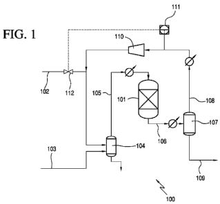
[0067] FIGS. 1-3 show a reaction zone 100 of a hydrogenation system suitable
for the
hydrogenation of acetic acid to form ethanol according to one embodiment of
the present
CA 02798632 2012-11-06
WO 2011/140468 PCT/US2011/035564
invention. Reaction zone 100 comprises a reactor 101, hydrogen feed line 102
and acetic acid
feed line 103. Hydrogen and acetic acid are fed to a vaporizer 104 via lines
102 and 103,
respectively, to create a vapor feed stream in line 105 that is directed to
reactor 101. Trace
amount of nitrogen also may be present in one or both of the feed streams. In
one embodiment,
lines 102 and 103 may be combined and jointly fed to the vaporizer 104. The
temperature of the
vapor feed stream in line 105 is preferably from 100 C to 350 C, e.g., from
120 C to 310 C or
from 150 C to 300 C. Any feed that is not vaporized is removed from vaporizer
104, as shown
in FIG. 1, and may be recycled thereto. In addition, although FIG. 1 shows
line 105 being
directed to the top of reactor 101, line 105 may be directed to the side,
upper portion, or bottom
of reactor 101.
[0068] Reactor 101 contains the catalyst that is used in the hydrogenation of
the carboxylic
acid, preferably acetic acid. During the hydrogenation process, a crude
ethanol product is
withdrawn, preferably continuously, from reactor 101 via line 106. The crude
ethanol product
may be condensed and fed to flasher 107, which, in turn, provides a vapor
stream 108 and a
liquid stream 109. The flasher 107 in one embodiment preferably operates at a
temperature from
20 C to 250 C, e.g., from 30 C to 225 C or from 60 C to 200 C. In one
embodiment, the
pressure of flasher 107 preferably is from 50 kPa to 2000 kPa, e.g., from 75
kPa to 1500 kPa or
from 100 to 1000 kPa. In one preferred embodiment the temperature and pressure
of the flasher
107 is similar to the temperature and pressure of the reactor 101.
[0069] Vapor stream 108 exiting the flasher 107 may comprise hydrogen, and by-
product
gases, such as methane, ethane, nitrogen, carbon monoxide and carbon dioxide.
The vapor
stream contains unreacted hydrogen in an amount between 90 to 100 mol. %,
e.g., between 92 to
98 mol. %, or between 93 to 97 mol.% and contains by-product gases in an
amount less than 10
mol.%, e.g., less than 5 mol. %, less than 3 mol. %, or less than 1 mol.%. In
one embodiment,
the by-product gases are selected from the group consisting of methane,
ethane, carbon dioxide,
carbon monoxide, nitrogen, and mixtures thereof. Methane concentration may be
less than 3
mol. %, e.g., less than 1.5 mol. % or less than 1.2 mol. %. Ethane
concentration may be less than
3 mol. %, e.g., less than 1 mol. % or less than 0.8 mol. %. Carbon dioxide
concentration may be
less than 3 mol. %, e.g., less than 0.8 mol. % or less than 0.5 mol. %. Carbon
monoxide
concentration may be less than 2 mol. %, e.g., less than 0.3 mol. %, or less
than 0.2 mol. %.
16
CA 02798632 2012-11-06
WO 2011/140468 PCT/US2011/035564
Nitrogen concentration may be less than 2 mol. %, e.g., less than 0.4 mol. %,
or less than 0.3
mol. %.
[0070] In an embodiment of the invention, unreacted hydrogen, along with by-
product gases, is
recycled and is returned to reactor 101 via recycle line 108, preferably
without a purge.
Furthermore, recycle line 108 may be combined with fresh hydrogen 102 before
being fed to
vaporizer 104. The pressure of recycle line 108 generally is lower than the
reactor 101, and
recycle line 108 is passed through a compressor 110. To maintain constant
pressure in reactor
103, a pressure analyzer 111 may measure the pressure of recycle line 108 and
control the
amount of fresh hydrogen 102 via valve 112. Pressure analyzer 111 may operate
continuously.
Generally, the pipeline pressure of fresh hydrogen 102 may be sufficient to
supply the pressure
for the reactor 101. As indicated above, the pressure of the reactor 101 may
be from 10 kPa to
3000 kPa, and constant pressure refers to maintaining a pressure that varies
by less than 5%, e.g.,
less than 3% or less than 1%. For example, if the reactor pressure is 100 kPa,
the constant
pressure is within 95 to 105 kPa. Although pressure analyzer 111 is shown
before compressor
110 in FIG. 1, in some embodiments, pressure analyzer may be after compressor
110.
[0071] As stated above, by-product gases, such as methane, ethane, carbon
monoxide, carbon
dioxide, and/or nitrogen, may be dissolved in the liquid stream 109 exiting
flasher 107.
Depending on the solubility limit of the by-product gas or mixtures of gases,
the concentration of
the dissolved by-product gases may vary. The solubility of a gas in a liquid
depends on
temperature, the partial pressure of the gas over the liquid, the nature of
the liquid and the nature
of the gas. As used herein, the term "dissolved by-product gas" or "dissolved
by-product gases"
refers to a dissolved material that is a gas at 1 atmospheric pressure and
room temperature.
[0072] In one embodiment, the dissolved by-product gases, such as methane,
ethane, carbon
monoxide, carbon dioxide and/or nitrogen, in a concentration from 0.00001 to
0.1 wt. %, e.g.,
0.0001 to 0.01 wt. % or 0.001 to 0.005 wt. %. Liquid stream 109 may be further
separated to
recover ethanol. The dissolved by-product gases may be vented from liquid
stream 109. In FIG.
2, the dissolved by-product gases are vented in a second flasher 113. In FIG.
3, the dissolved by-
product gases are vented from the overhead of a distillation column 114. In
some embodiments,
there may be purge of by-product gases in both a second flasher 113 as shown
in FIG. 2 and
from the overhead of distillation column 114. As used herein, the term "purge"
may mean
purging of a substance in either a liquid or a vapor form.
17
CA 02798632 2012-11-06
WO 2011/140468 PCT/US2011/035564
[0073] In an embodiment of the invention shown in FIG. 2, liquid stream 109 is
fed to a second
flasher 113, which, in turn, provides a second vapor stream 115 and a second
liquid stream 116.
As a result, light-weight, by-product gases, i.e., methane, carbon monoxide
and carbon dioxide,
may be purged from the system. Second flasher 113 may operate at a lower
temperature and/or
pressure than flasher 107. In one embodiment, the temperature of second
flasher 113 preferably
is from 20 C to 100 C, e.g., from 30 C to 85 C or from 40 C to 70 C. In one
embodiment, the
temperature of second flasher 113 preferably is at least 50 C lower than first
flasher 107, e.g., at
least 75 C lower or at least 100 C lower. The pressure of second flasher 107
preferably is from
0.1 kPa to 1000 kPa, e.g., from 0.1 kPa to 500 kPa or from 0.1 kPa to 100 kPa.
In one
embodiment, the pressure of second flasher 107 preferably is at least 50 kPa
lower than first
flasher 107, e.g., at least 100 kPa lower or at least 200 kPa lower.
[0074] Second vapor stream 115 may comprise at least 1 mol.% by-product gases,
e.g., at least
mol.% or at least 10 mol.%. Preferably these by-product gases are vented from
the system.
Second liquid stream 116 may be further separated to recover ethanol.
Preferably, second liquid
stream 116 contains less dissolved by-product gases than liquid stream 109.
[0075] In another embodiment of the invention shown in FIG. 3, liquid stream
109 is fed to a
distillation column 114. In distillation column 114, liquid stream is
separated to recover ethanol.
Depending on the acetic acid conversion and operation of column 114, unreacted
acetic acid,
water, and other heavy components, if present, are removed from the
composition in line 117 and
are withdrawn, preferably continuously, as residue. In some embodiments,
especially with
higher conversions of acetic acid of at least 80%, or at least 90%, it may be
beneficially to
remove a majority of water in line 117 along with substantially all the acetic
acid in residue
stream 117. Residue stream 117 may be recycled to reaction zone 100. In
addition, a portion of
the water in residue stream 117 may be separated and purged with the acid rich
portion being
returned to reaction zone 100. In other embodiments, the residue stream 117
may be a dilute
acid stream that may be treated in a weak acid recovery system or sent to a
reactive distillation
column to convert the acid to esters.
[0076] Column 114 also forms an overhead distillate, which is withdrawn in
line 118, and
which may be condensed and collected in an overhead receiver 119. A vent
stream 120 may be
withdrawn from receiver 119 to remove by-product gases, such as methane,
ethane, carbon
monoxide, carbon dioxide, nitrogen and mixtures thereof. Vent stream 120 may
comprise at
18
CA 02798632 2012-11-06
WO 2011/140468 PCT/US2011/035564
least 1 mol.% by-product gases, e.g., at least 5 mol.% or at least 10 mol.%.
The liquid stream
121 from receiver 119 may be refluxed, for example, at a ratio of from 10:1 to
1:10, e.g., from
3:1 to 1:3 or from 1:2 to 2:1. Preferably, ethanol may be recovered from the
liquid stream 121.
[0077] In FIGS. 1-3, vapor stream 108 is recycled to reactor 101 preferably
without a purge.
Preferably, by-product gases are purged from the dissolved gases in the liquid
stream 109. In
some embodiments, there may be a smaller purge from vapor stream 108, e.g.,
less than 5% of
vapor stream 108 is purged, e.g., less than 1% or less than 0.5%. Generally,
when smaller purges
are taken it is still preferable to purge a majority of the by-products
through the second flasher in
FIG. 2 or from the overhead in FIG. 3. However, in some embodiments a larger
purge of less
than 15% of vapor stream, e.g. less than 10% or less than 8%, may be taken.
Thus, at least 85%
of the gases separated from the crude ethanol product are returned to the
reactor via vapor stream
108 and more preferably at least 90%, e.g., at least 92% or at least 99%.
[0078] In FIG. 4, there is provided a reaction zone 100 having analyzers 150
and/or 151 for
measuring the composition of vapor stream 108 that exits flasher 109.
Analyzers 150 measures
the composition of vapor stream 108 directly. Analyzers 151 measure the
content of a slipstream
152 of vapor stream 108. In some embodiments, a reaction zone may comprise
either analyzer
150 or analyzer 151. When any of the by-product gases exceeds a threshold
value, analyzers 150
or 151 communicate with a control system to operate valve 153 to release a
purge stream 154. A
pressure analyzer 155 may monitor the purge stream 154 to control the amount
of fresh hydrogen
102 via valve 112, and thus maintain a constant pressure reaction zone 100.
[0079] Analyzers are widely used to monitor vapor streams by on-line gas
chromatography,
GC/MS, on-line infrared spectroscopy, NIR, FTNIR, UV, Visible light, LED,
laser or mass
spectrometry. An on-line gas chromatography or infrared spectroscopy may be
used to analyze
the vapor stream 108 for one of the by-product gases, e.g., methane, ethane,
carbon monoxide, or
carbon dioxide. The on-line techniques may be backed up by daily samples to
cross check on-
line analysis. A mass spectrometric analyzer may required a sample from vapor
stream 108 and
may be used with slipstream 152 to detect the concentration of the by-product
gases. In one
embodiment, analyzer 150 may be an on-line analyzer and analyzer 151 may be an
on-line
analyzer or a mass spectrometric analyzer. In a preferred embodiment, on-line
techniques are
used to monitor the concentration of the by-product gases.
[0080] Once the concentration of one or more of the by-product gases exceeds a
threshold
19
CA 02798632 2012-11-06
WO 2011/140468 PCT/US2011/035564
value, the analyzer communicates with the controller to release a purge stream
154 by opening
valve 153. As shown in FIG. 4, purge stream 154 is taken from slipstream 151.
In other
embodiments, purge stream may be taken directly from vapor stream 108. The
threshold value is
a preset or controllable value that may be monitored to release by-products
from vapor stream
108. The threshold value may be different for each by-product gas. In
addition, there may a
total threshold value for all the by-product gases. For example, the threshold
value for all the by-
product gases may be at least 5 mol.%, e.g., at least 8 mol.%, or at least 10
mol.%. Also, the
threshold value for any of the by-product gases may at least 5 mol.%, e.g., at
least 8 mol.%, or at
least 10 mol.%. In some embodiments, the amount for individual gases may be
lower When the
analyzers 150 or 151 detect a concentration of by-product gases that exceeds
at least 1 mol.%,
the valve is opened to release a purge stream 154. The amount of vapor stream
108 that is
purged may depend on the concentration of the by-product gases in vapor
stream. Thus, in some
embodiments, more than 1% of the vapor stream is purged, e.g., more than 3% or
more than 5%.
Preferably, less than 15% of vapor stream is purged when a by-product gas
exceeds a threshold
value, e.g. less than 10% or less than 8%.
[0081] Suitable threshold values for each of the by-product gases are as
follows. It is
understood, that depending on the operation of the reaction system 100, other
threshold values
may be selected. For methane, suitable threshold values include greater than
1.2 mol.%, e.g.,
greater than 1.5 mol.% or greater than 3 mol.%. For ethane, suitable threshold
values include
greater than 0.8 mol.%, e.g., greater than 1 mol.% or greater than 3 mol.%.
For carbon
monoxide, suitable threshold values include greater than 0.5 mol.%, e.g.,
greater than 0.8 mol.%
or greater than 3 mol.%. For carbon dioxide, suitable threshold values include
greater than 0.2
mol.%, e.g., greater than 0.3 mol.% or greater than 2 mol.%. Carbon monoxide
is a known
catalyst poison and monitoring carbon monoxide concentrations may be
advantageous to prevent
recycling large amounts of carbon monoxide that may cause reactor
inefficiencies.
[0082] An advantage to using analyzers 150 or 151 is that vapor stream 108 is
purged when
by-product gases are present in larger concentrations. This allows a majority
of the hydrogen to
be recycled without a substantially lose of reactants. In an embodiment of the
present invention,
preferably, less than 15 mol.% of the by-product gases is purged from the
system. More
preferably, there is substantially no purge in the system.
[0083] A hydrogenation system 200 suitable for the hydrogenation of acetic
acid and
CA 02798632 2012-11-06
WO 2011/140468 PCT/US2011/035564
separating ethanol from the crude reaction mixture according to one embodiment
of the present
invention is shown in FIG. 5. The system 200 comprises reaction zone 201 and
distillation zone
202. The exemplary system in FIG. 5 is shown with the reaction zone from FIG.
4, but it should
be appreciated that any of the reactor zones from FIGS. 1-3 may be used in the
hydrogenation
system.
[0084] Hydrogen and acetic acid are fed to a vaporizer 210 via lines 204 and
205, respectively,
to create a vapor feed stream in line 211 that is directed to reactor 203. In
one embodiment, lines
204 and 205 may be combined and jointly fed to the vaporizer 210, e.g., in one
stream containing
both hydrogen and acetic acid. The temperature of the vapor feed stream in
line 211 is
preferably from 100 C to 350 C, e.g., from 120 C to 310 C or from 150 C to 300
C. Any feed
that is not vaporized is removed from vaporizer 210, as shown in FIG. 2, and
may be recycled
thereto. In addition, although FIG. 2 shows line 211 being directed to the top
of reactor 203, line
211 may be directed to the side, upper portion, or bottom of reactor 203.
Further modifications
and additional components to reaction zone 201 are described below.
[0085] Reactor 203 contains the catalyst that is used in the hydrogenation of
the carboxylic
acid, preferably acetic acid. In one embodiment, one or more guard beds (not
shown) may be
used to protect the catalyst from poisons or undesirable impurities contained
in the feed or
return/recycle streams. Such guard beds may be employed in the vapor or liquid
streams.
Suitable guard bed materials are known in the art and include, for example,
carbon, silica,
alumina, ceramic, or resins. In certain embodiments of the invention, the
guard bed media is
functionalized to trap particular species such as sulfur or halogens. During
the hydrogenation
process, a crude ethanol product is withdrawn, preferably continuously, from
reactor 203 via line
212.
[0086] The crude ethanol product may be condensed and fed to flasher 206,
which, in turn,
provides a vapor stream and a liquid stream. The flasher 206 may operate at a
temperature of
from 30 C to 500 C, e.g., from 70 C to 400 C or from 100 C to 350 C. The
pressure of flasher
206 may be from 50 kPa to 2000 kPa, e.g., from 75 kPa to 1500 kPa or from 100
to 1000 kPa. In
another embodiment, the temperature and pressure of the flasher is similar to
the temperature and
pressure of the reactor 203.
[0087] The vapor stream 213 exiting the flasher 206 may comprise hydrogen and
by-product
gases. A reaction zone 200 having analyzers 250 and/or 251 for measuring the
composition of
21
CA 02798632 2012-11-06
WO 2011/140468 PCT/US2011/035564
vapor stream 213 that exits flasher 206. Analyzers 250 measures the
composition of vapor
stream 213 directly. Analyzers 251 measure the content of a slipstream 252 of
vapor stream 209.
In some embodiments, a reaction zone may comprise either analyzer 250 or
analyzer 251. When
any of the by-product gases exceeds a threshold value, analyzers 250 or 251
communicate with a
control system to operate valve 253 to release a purge stream 254. A pressure
analyzer 255 may
monitor the purge stream 254 to control the amount of fresh hydrogen 204 via
valve 256, and
thus maintain a constant pressure reaction zone 200. In one embodiment, vapor
stream 213
preferably comprises by-products having a concentration below the threshold
value and no purge
is necessary from vapor stream 213. The remaining vapor stream 213 that is not
purged passes
through compressor 214 and is returned to reactor 203.
[0088] The liquid from flasher 206 is withdrawn and pumped as a feed
composition via line
215 to the side of first column 207, also referred to as the acid separation
column. In one
embodiment, liquid stream 215 may contain dissolved by-product gases and
hydrogen. In one
embodiment, the dissolved by-product gases, such as methane, ethane, carbon
monoxide, carbon
dioxide and/or nitrogen, in a concentration amount from 0.00001 to 0.1 wt.%,
e.g., 0.0001 to
0.01 wt. % or 0.001 to 0.005 wt. %. The contents of line 215 typically will be
substantially
similar to the product obtained directly from the reactor, and may, in fact,
also be characterized
as a crude ethanol product. Generally a large amount of hydrogen may be
removed by flasher
206. Exemplary components of liquid in line 215 are provided in Table 2. It
should be
understood that liquid line 215 may contain other components, not listed, such
as components in
the feed.
TABLE 2
FEED COMPOSITION
Conc. (wt.%) Conc. (wt.%) Conc. (wt.%)
Ethanol 5 to 70 10 to 60 15 to 50
Acetic Acid < 90 5 to 80 15 to 70
Water 5 to 35 5 to 30 10 to 30
Ethyl Acetate < 20 0.001 to 15 1 to 12
Acetaldehyde < 10 0.001 to 3 0.1 to 3
Acetal < 5 0.001 to 2 0.005 to 1
Acetone < 5 0.0005 to 0.05 0.001 to 0.03
Other Esters < 5 < 0.005 < 0.001
Other Ethers < 5 < 0.005 < 0.001
Other Alcohols < 5 < 0.005 < 0.001
22
CA 02798632 2012-11-06
WO 2011/140468 PCT/US2011/035564
[0089] The amounts indicated as less than (<) in the tables throughout present
application are
preferably not present and if present may be present in trace amounts or in
amounts greater than
0.0001 wt.%.
[0090] The "other esters" in Table 3 may include, but are not limited to,
ethyl propionate,
methyl acetate, isopropyl acetate, n-propyl acetate, n-butyl acetate or
mixtures thereof. The
"other ethers" in Table 3 may include, but are not limited to, diethyl ether,
methyl ethyl ether,
isobutyl ethyl ether or mixtures thereof. The "other alcohols" in Table 3 may
include, but are not
limited to, methanol, isopropanol, n-propanol, n-butanol or mixtures thereof.
In one
embodiment, the feed composition, e.g., line 215, may comprise propanol, e.g.,
isopropanol
and/or n-propanol, in an amount from 0.001 to 0.1 wt.%, from 0.001 to 0.05
wt.% or from 0.001
to 0.03 wt.%. In should be understood that these other components may be
carried through in
any of the distillate or residue streams described herein and will not be
further described herein,
unless indicated otherwise.
[0091] Optionally, the crude ethanol product may be fed directly to the acid
separation column
as a vapor feed and the by-product gases may be purged from a vent from the
overhead of the
column 207.
[0092] When the content of acetic acid in line 215 is less than 5 wt.%, the
acid separation
column 207 may be skipped and line 215 may be introduced directly to second
column 208, also
referred to herein as a "light ends column."
[0093] In the embodiment shown in FIG. 2, line 215 is introduced in the lower
part of first
column 207, e.g., lower half or lower third. Depending on the acetic acid
conversion and
operation of column 207, unreacted acetic acid, water, and other heavy
components, if present,
are removed from the composition in line 215 and are withdrawn, preferably
continuously, as
residue. In some embodiments, especially with higher conversions of acetic
acid of at least
80%, or at least 90%, it may be beneficially to remove a majority of water in
line 215 along with
substantially all the acetic acid in residue stream 216. Residue stream 216
may be recycled to
reaction zone 201. In addition, a portion of the water in residue stream 216
may be separated
and purged with the acid rich portion being returned to reaction zone 201. In
other
embodiments, the residue stream 216 may be a dilute acid stream that may be
treated in a weak
acid recovery system or sent to a reactive distillation column to convert the
acid to esters.
23
CA 02798632 2012-11-06
WO 2011/140468 PCT/US2011/035564
[0094] First column 207 also forms an overhead distillate, which is withdrawn
in line 217, and
which may be condensed and collected in an overhead receiver (not shown). A
vent stream 260
may be withdrawn from receiver to remove by-product gases, such as methane,
ethane, carbon
monoxide, carbon dioxide, nitrogen and mixtures thereof. Vent stream 120 may
comprise at
least 1 mol.% by-product gases, e.g., at least 5 mol.% or at least 10 mol.%.
Preferably it is
desirable to remove the by-product gases dissolved in liquid stream 215 after
the first column
207. A liquid stream from received may be refluxed, for example, at a ratio of
from 10:1 to 1:10,
e.g., from 3:1 to 1:3 or from 1:2 to 2:1.
[0095] The columns shown in FIGS. 1-5, may comprise any distillation column
capable of
performing the desired separation and/or purification. Each column preferably
comprises a tray
column having from 1 to 150 trays, e.g., from 10 to 100 trays, from 20 to 95
trays or from 30 to
75 trays. The trays may be sieve trays, fixed valve trays, movable valve
trays, or any other
suitable design known in the art. In other embodiments, a packed column may be
used. For
packed columns, structured packing or random packing may be employed. The
trays or packing
may be arranged in one continuous column or they may be arranged in two or
more columns
such that the vapor from the first section enters the second section while the
liquid from the
second section enters the first section, etc.
[0096] The associated condensers and liquid separation vessels that may be
employed with
each of the distillation columns may be of any conventional design and are
simplified in FIG. 5.
As shown in FIG. 5, heat may be supplied to the base of each column or to a
circulating bottom
stream through a heat exchanger or reboiler. Other types of reboilers, such as
internal reboilers,
may also be used. The heat that is provided to the reboilers may be derived
from any heat
generated during the process that is integrated with the reboilers or from an
external source such
as another heat generating chemical process or a boiler. Although one reactor
and one flasher
are shown in FIG. 5, additional reactors, flashers, condensers, heating
elements, and other
components may be used in various embodiments of the present invention. As
will be
recognized by those skilled in the art, various condensers, pumps,
compressors, reboilers, drums,
valves, connectors, separation vessels, etc., normally employed in carrying
out chemical
processes may also be combined and employed in the processes of the present
invention.
[0097] The temperatures and pressures employed in the columns may vary. As a
practical
matter, pressures from 10 kPa to 3000 kPa will generally be employed in these
zones although in
24
CA 02798632 2012-11-06
WO 2011/140468 PCT/US2011/035564
some embodiments subatmospheric pressures or superatmospheric pressures may be
employed.
Temperatures within the various zones will normally range between the boiling
points of the
composition removed as the distillate and the composition removed as the
residue. As will be
recognized by those skilled in the art, the temperature at a given location in
an operating
distillation column is dependent on the composition of the material at that
location and the
pressure of column. In addition, feed rates may vary depending on the size of
the production
process and, if described, may be generically referred to in terms of feed
weight ratios.
[0098] When column 207 is operated under standard atmospheric pressure, the
temperature of
the residue exiting in line 216 from column 207 preferably is from 95 C to 120
C, e.g., from
105 C to 117 C or from 110 C to 115 C. The temperature of the distillate
exiting in line 217
from column 207 preferably is from 70 C to 110 C, e.g., from 75 C to 95 C or
from 80 C to
90 C. In other embodiments, the pressure of first column 207 may range from
0.1 kPa to 510
kPa, e.g., from 1 kPa to 475 kPa or from 1 kPa to 375 kPa. In one exemplary
embodiment a
distillate and residue compositions for first column 207 are provided in Table
3 below, excluding
by-product gases. Note that these compositions may change depending on acetic
acid
conversion, the operation of the column and whether a majority of the water is
removed in the
residue. It should also be understood that the distillate and residue may also
contain other
components, not listed, such as components in the feed. For convenience, the
distillate and
residue of the first column may also be referred to as the "first distillate"
or "first residue." The
distillates or residues of the other columns may also be referred to with
similar numeric
modifiers (second, third, etc.) in order to distinguish them from one another,
but such modifiers
should not be construed as requiring any particular separation order.
CA 02798632 2012-11-06
WO 2011/140468 PCT/US2011/035564
TABLE 3
FIRST COLUMN
Conc. (wt.%) Conc. (wt.%) Conc. (wt.%)
Distillate
Ethanol 20 to 75 30 to 70 40 to 65
Water 10 to 40 15 to 35 20 to 35
Acetic Acid < 2 0.001 to 0.5 0.01 to 0.2
Ethyl Acetate < 60 5.0 to 40 10 to 30
Acetaldehyde < 10 0.001 to 5 0.01 to 4
Acetal < 0.1 < 0.1 < 0.05
Acetone < 0.05 0.001 to 0.03 0.01 to 0.025
Residue
Acetic Acid 60 to 100 70 to 95 85 to 92
Water < 30 1 to 20 1 to 15
Ethanol < 1 < 0.9 < 0.07
[0099] Some species, such as acetals, may decompose in column 207 to low or
even no
detectable amounts. In addition, there may be a non-catalyzed equilibrium
reaction after the
crude ethanol product 212 exits the reactor 203 in liquid feed 215. Depending
on the
concentration of acetic acid, the equilibrium may be driven towards formation
of ethyl acetate.
The equilibrium may be regulated using the residence time and/or temperature
of liquid feed
215.
[0100] The first distillate in line 217 preferably comprises ethanol, ethyl
acetate, and water,
along with other impurities, which may be difficult to separate due to the
formation of binary and
tertiary azeotropes. The first distillate in line 217 is introduced to the
second column 208, also
referred to as the "light ends column," preferably in the middle part of
column 208, e.g., middle
half or middle third. Second column 208 may be a tray column or packed column.
In one
embodiment, second column 208 is a tray column having from 5 to 70 trays,
e.g., from 15 to 50
trays or from 20 to 45 trays. As one example, when a 25 tray column is
utilized in a column
without water extraction, line 217 is introduced at tray 17. Also when a 30
tray column is used,
without water extraction, line 217 may be introduced at tray 2. In one
embodiment, the second
column 208 may be an extractive distillation column. In such embodiments, an
extraction agent,
such as water, may be added to second column 208. If the extraction agent
comprises water, it
may be obtained from an external source or from an internal return/recycle
line from one or more
of the other columns.
26
CA 02798632 2012-11-06
WO 2011/140468 PCT/US2011/035564
[0101] In some embodiments, a portion of the water in first distillate 217 may
be removed
prior to second column 208, using one or more membranes, and/or adsorptions
units.
[0102] Although the temperature and pressure of second column 208 may vary,
when at
atmospheric pressure the temperature of the second residue exiting in line 218
from second
column 208 preferably is from 60 C to 90 C, e.g., from 70 C to 90 C or from 80
C to 90 C.
The temperature of the second distillate exiting in line 220 from second
column 208 preferably is
from 50 C to 90 C, e.g., from 60 C to 80 C or from 60 C to 70 C. Second column
208 may
operate at a reduced pressure, near or at vacuum conditions, to further favor
separation of ethyl
acetate and ethanol. In other embodiments, the pressure of second column 208
may range from
0.1 kPa to 510 kPa, e.g., from 1 kPa to 475 kPa or from 1 kPa to 375 kPa.
Exemplary
components for the distillate and residue compositions for second column 208
are provided in
Table 4 below. It should be understood that the distillate and residue may
also contain other
components, not listed, such as components in the feed.
TABLE 4
SECOND COLUMN
Conc. (wt.%) Conc. (wt.%) Conc. (wt.%)
Distillate
Ethyl Acetate 10 to 90 25 to 90 50 to 90
Acetaldehyde 1 to 25 1 to 15 1 to 8
Water 1 to 25 1 to 20 4 to 16
Ethanol < 30 0.001 to 15 0.01 to 5
Acetal < 5 0.001 to 2 0.01 to 1
Residue
Water 5 to 70 30 to 60 30 to 50
Ethanol 20 to 95 30 to 70 40 to 70
Ethyl Acetate < 3 0.001 to 2 0.001 to 0.5
Acetic Acid < 0.5 0.001 to 0.3 0.001 to 0.2
[0103] The weight ratio of ethanol in the second residue to ethanol in the
second distillate
preferably is at least 3:1, e.g., at least 6:1, at least 8:1, at least 10:1 or
at least 15:1. The weight
ratio of ethyl acetate in the second residue to ethyl acetate in the second
distillate preferably is
less than 0.4:1, e.g., less than 0.2:1 or less than 0.1:1. In embodiments that
use an extractive
27
CA 02798632 2012-11-06
WO 2011/140468 PCT/US2011/035564
column with water as an extraction agent as the second column 208, the weight
ratio of ethyl
acetate in the second residue to ethyl acetate in the second distillate
approaches zero.
[0104] Returning to the second distillate 220, which comprises ethyl acetate
and/or
acetaldehyde, preferably is refluxed as shown in FIG. 2, for example, at a
reflux ratio of from
1:30 to 30:1, e.g., from 1:5 to 5:1 or from 1:3 to 3:1. The second distillate
220 or portion thereof
may be returned reactor 203. In some embodiments, it may be advantageous to
return a portion
of second distillate 220 to reactor 203. In one embodiment, second distillate
may be fed via line
220 to acetaldehyde removal column (not shown) to recover aldehyde that may be
recycled to
the reactor 203. Second distillate 220 may also be hydrolyzed or fed to an
hydrogenolysis
reactor to produce ethanol from ethyl acetate. Additionally, second distillate
220 may be purged
from system.
[0105] As shown, the second residue from the bottom of second column 208,
which comprises
ethanol and water, is fed via line 218 to third column 209, also referred to
as the "product
column." More preferably, the second residue in line 218 is introduced in the
lower part of third
column 209, e.g., lower half or lower third. Third column 209 recovers
ethanol, which
preferably is substantially pure other than the azeotropic water content, as
the distillate in line
219. The distillate of third column 209 preferably is refluxed as shown in
FIG. 2, for example, at
a reflux ratio of from 1:10 to 10:1, e.g., from 1:3 to 3:1 or from 1:2 to 2:1.
The third residue in
line 221, which preferably comprises primarily water, preferably is removed
from the system
200 or may be partially returned to any portion of the system 200. Third
column 209 is
preferably a tray column as described above and preferably operates at
atmospheric pressure.
The temperature of the third distillate exiting in line 219 from third column
209 preferably is
from 60 C to 110 C, e.g., from 70 C to 100 C or from 75 C to 95 C. The
temperature of the
third residue exiting from third column 209 preferably is from 70 C to 115 C,
e.g., from 80 C to
110 C or from 85 C to 105 C, when the column is operated at atmospheric
pressure. Exemplary
components of the distillate and residue compositions for third column 209 are
provided in Table
below. It should be understood that the distillate and residue may also
contain other
components, not listed, such as components in the feed.
28
CA 02798632 2012-11-06
WO 2011/140468 PCT/US2011/035564
TABLE 5
THIRD COLUMN
Conc. (wt.%) Conc. (wt.%) Conc. (wt.%)
Distillate
Ethanol 75 to 96 80 to 96 85 to 96
Water < 12 1 to 9 3 to 8
Acetic Acid < 1 0.001 to 0.1 0.005 to 0.01
Ethyl Acetate < 5 0.001 to 4 0.01 to 3
Residue
Water 75 to 100 80 to 100 90 to 100
Ethanol < 0.8 0.001 to 0.5 0.005 to 0.05
Ethyl Acetate < 1 0.001 to 0.5 0.005 to 0.2
Acetic Acid < 2 0.001 to 0.5 0.005 to 0.2
[0106] Any of the compounds that are carried through the distillation process
from the feed or
crude reaction product generally remain in the third distillate in amounts of
less 0.1 wt.%, based
on the total weight of the third distillate composition, e.g., less than 0.05
wt.% or less than 0.02
wt.%. In one embodiment, one or more side streams may remove impurities from
any of the
columns 207, 208 and/or 209 in the system 200. Preferably at least one side
stream is used to
remove impurities from the third column 209. The impurities may be purged
and/or retained
within the system 200.
[0107] The ethanol product is taken from the third distillate 219. Third
distillate 219 may be
further purified to form an anhydrous ethanol product stream, i.e., "finished
anhydrous ethanol,"
using one or more additional separation systems, such as, for example,
distillation columns (e.g.,
a finishing column), membranes, adsorption units, or molecular sieves.
Anhydrous ethanol may
be suitable for fuel applications.
[0108] The final ethanol product by the present invention may be taken from
the third distillate
219. The ethanol product may be an industrial grade ethanol comprising from 75
to 96 wt.%
ethanol, e.g., from 80 to 96 wt.% or from 85 to 96 wt.% ethanol, based on the
total weight of the
ethanol product. Exemplary finished ethanol compositional ranges are provided
below in Table
6.
29
CA 02798632 2012-11-06
WO 2011/140468 PCT/US2011/035564
TABLE 6
FINISHED ETHANOL COMPOSITIONS
Component Conc. (wt.%) Conc. (wt.%) Conc. (wt.%)
Ethanol 75 to 96 80 to 96 85 to 96
Water < 12 1 to 9 3 to 8
Acetic Acid < 1 < 0.1 < 0.01
Ethyl Acetate < 2 < 0.5 < 0.05
Acetal < 0.05 < 0.01 < 0.005
Acetone < 0.05 < 0.01 < 0.005
Isopropanol < 0.5 < 0.1 < 0.05
n-propanol < 0.5 < 0.1 < 0.05
[0109] The finished ethanol composition of the present invention preferably
contains very low
amounts, e.g., less than 0.5 wt.%, of other alcohols, such as methanol,
butanol, isobutanol,
isoamyl alcohol and other C4-C20 alcohols. In one embodiment, the amount of
isopropanol in the
finished ethanol composition is from 80 to 1,000 wppm, e.g., from 95 to 1,000
wppm, from 100
to 700 wppm, or from 150 to 500 wppm. In one embodiment, the finished ethanol
composition
is substantially free of acetaldehyde, optionally comprising less than 8 wppm
acetaldehyde, e.g.,
less than 5 wppm or less than 1 wppm.
[0110] In some embodiments, when further water separation is used, the ethanol
product may
be withdrawn as a stream from the water separation unit as discussed above. In
such
embodiments, the ethanol concentration of the ethanol product may be higher
than indicated in
Table 7, and preferably is greater than 97 wt.% ethanol, e.g., greater than 98
wt.% or greater than
99.5 wt.%. The ethanol product in this aspect preferably comprises less than 3
wt.% water, e.g.,
less than 2 wt.% or less than 0.5 wt.%.
[0111] The finished ethanol composition produced by the embodiments of the
present
invention may be used in a variety of applications including application as
fuels, solvents,
chemical feedstocks, pharmaceutical products, cleansers, sanitizers,
hydrogenation transport or
consumption. In fuel applications, the finished ethanol composition may be
blended with
gasoline for motor vehicles such as automobiles, boats and small piston engine
aircraft. In non-
fuel applications, the finished ethanol composition may be used as a solvent
for toiletry and
cosmetic preparations, detergents, disinfectants, coatings, inks, and
pharmaceuticals. The
finished ethanol composition may also be used as a processing solvent in
manufacturing
processes for medicinal products, food preparations, dyes, photochemicals and
latex processing.
CA 02798632 2012-11-06
WO 2011/140468 PCT/US2011/035564
[0112] The finished ethanol composition may also be used as a chemical
feedstock to make
other chemicals such as vinegar, ethyl acrylate, ethyl acetate, ethylene,
glycol ethers,
ethylamines, aldehydes, and higher alcohols, especially butanol. In the
production of ethyl
acetate, the finished ethanol composition may be esterified with acetic acid.
In another
application, the finished ethanol composition may be dehydrated to produce
ethylene. Any
known dehydration catalyst can be employed to dehydrate ethanol, such as those
described in
copending U.S. Pub. Nos. 2010/0030002 and 2010/0030001, the entire contents
and disclosures
of which are hereby incorporated by reference. A zeolite catalyst, for
example, may be
employed as the dehydration catalyst. Preferably, the zeolite has a pore
diameter of at least
about 0.6 nm, and preferred zeolites include dehydration catalysts selected
from the group
consisting of mordenites, ZSM-5, a zeolite X and a zeolite Y. Zeolite X is
described, for
example, in U.S. Pat. No. 2,882,244 and zeolite Y in U.S. Pat. No. 3,130,007,
the entireties of
which are hereby incorporated herein by reference.
[0113] In order that the invention disclosed herein may be more efficiently
understood, an
example is provided below. The following examples describe the various
distillation processes
of the present invention.
Examples
[0114] The system was set up to measure the accumulation rate of gaseous
byproducts in the
recycle gas. Pressure for the initial reactions was set at about 2,170 kPa.
Temperature for the
system was set at 300 C. The acetic acid flow rate was set at 3.56 ml/min
acetic acid and the
recycle flow rate was set at 10 L/min. Initially, the acid flow rate was set
to zero and the vent
line open to 100% to purge all the gases, but hydrogen, from the loop. The
presence of hydrogen
was monitored using an online gas chromatographer (GC). Once it was determined
that only
hydrogen was present in the system, the vent was closed and the acetic acid
flow line was
opened. The accumulation of gaseous byproducts in the recycle loop was
measured for 24-hours
and shown in FIG. 6.
[0115] As shown in FIG. 6, the main products in the recycle loop are methane,
ethane, carbon
monoxide and carbon dioxide. The by-product components build up rapidly on the
closing of the
valve, but then reach a steady-state composition. For example, carbon monoxide
appears to have
reached a steady state after about five hours and remained at a 0.20 mol.%
concentration during
31
CA 02798632 2012-11-06
WO 2011/140468 PCT/US2011/035564
the next 19 hours of the experiment. Similarly, nitrogen, carbon dioxide,
ethane and methane all
reached a plateau after about 5- 11 hours.
[0116] The experiment above was repeated and the reactions were monitored over
the course
of 3-days, as shown in FIG. 7. The accumulation of gaseous byproducts in the
recycle loop was
measured at three different intervals (as indicated by the vertical line) to
determine the effect of
the gaseous byproducts in the recycle loop over time. The conversions and
selectivities are
shown in Table 7.
Table 7
Conversion Selectivity ( Io)
(%) EtOH EtOAc AcH DEA
Sample 1 38.19 88.88 8.95 1.74 0.43
Sample 2 36.60 88.92 8.88 1.67 0.52
Sample 3 36.44 89.33 8.49 1.74 0.44
[0117] As shown in Table 7, the selectivities of the reactor products appeared
to be unaffected
by the accumulation of the gaseous byproducts. The conversion seemed to be
slightly higher at
the beginning of the experiment when the level of the components in the
recycled gas loop was
low. The temperature profile during the experiment was steady and thus
temperature did not
play a role in the selectivities of the reactor products.
[0118] The experiment was repeated at 250 C and 275 C. The results of these
experiments is
shown in FIG. 8 and FIG. 9, respectively. As shown in both figures, all
components expect
nitrogen reached steady state after roughly 12 hours. It is believed that
nitrogen entered the
system through the liquid feed line.
[0119] While the invention has been described in detail, modifications within
the spirit and
scope of the invention will be readily apparent to those of skill in the art.
In addition, it should
be understood that aspects of the invention and portions of various
embodiments and various
features recited herein and/or in the appended claims may be combined or
interchanged either in
whole or in part. In the foregoing descriptions of the various embodiments,
those embodiments
which refer to another embodiment may be appropriately combined with one or
more other
embodiments, as will be appreciated by one of skill in the art. Furthermore,
those of ordinary
skill in the art will appreciate that the foregoing description is by way of
example only, and is not
intended to limit the invention.
32