Note: Descriptions are shown in the official language in which they were submitted.
CA 02799058 2012-11-08
WO 2011/141919 PCT/IL2011/000383
METHOD AND APPARATUS FOR DISPENSING ITEMS
FIELD OF THE INVENTION
The present invention relates to an apparatus and method for dispensing a
multiplicity of discrete items into groups (or "batches"), each group
containing a
predetermined number of the items.
BACKGROUND OF THE INVENTION
It is frequently required to dispense items of particulate matter into batches
of
known quantity. Examples include dispensing candies, seeds or medicinal pills
into
bottles, sachets or other containers, sorting rough diamonds into packages or
containers of approximately equal number of samples, such as to enable
different
evaluators to estimate the quality and worth of the whole, or the like.
In some dispensing tasks, the finished container must not contain less than
the
predetermined number of items. For example, when dispensing certain pills, a
full
treatment cycle may have to be provided, therefore at least the predetermined
number
of items must be provided in each container.
On the other hand, the dispensed items may be expensive, so if too many of the
containers contain more than the predetermined number of items, it translates
to direct
loss to the supplier of the items or to the packing organization.
In many dispensing machines, the items are transported along a conveyor, at
the end of which they fall or are otherwise collected into containers. Thus,
if the items
are put onto the conveyor in a single file, then a simple counting or
weighting
mechanism may provide satisfactory results. However, such a mechanism is
inherently
slower and therefore enables the dispensing of fewer items than if the items
were
freely placed on the conveyor without posing such limitations.
Furthermore, some dispensing machines also utilize various barriers for
physically preventing items from falling off the conveyor once the desired
amount has
been reached.
U.S. Patent No. 5,473,703 to Smith, entitled "Methods and apparatus for
controlling the feed rate of a discrete object sorter/counter", discloses a
controller
which adjusts the vibrator to oscillate the feed bowl at a predetermined
amplitude until
the sensor array senses a first object. The controller then adjusts the
vibrator to
1
CA 02799058 2012-11-08
WO 2011/141919 PCT/IL2011/000383
oscillate the feed bowl at a lower amplitude and monitors the sensing of other
objects.
Time intervals between objects being sensed are monitored and the controller
adjusts
the vibrator to oscillate the feed bowl at a lower or higher amplitude to
maintain a
constant feed rate. A count of objects sensed is maintained and compared to a
predetermined maximum count. When the count of objects equals a predetermined
number less than the maximum count, the controller adjusts the vibrator to
oscillate the
feed bowl at a lower amplitude to lower the feed rate. When the count of
objects
equals the maximum count, the controller activates a gate closing the chute.
U.S. Patent No. 6,659,304 to Geltser et al., entitled "Cassettes for systems
which feed, count and dispense discrete objects", discloses a high capacity
cassette for
an object counting and dispensing system, that includes, inter alia, a
structure which
feeds the discrete objects in single file toward an exit hole.
U.S. Patent No. 6,449,927 to Hebron et al., entitled "Integrated automated
drug
dispenser method and apparatus", discloses, inter alia, singulation control,
which is a
process by which drugs move through a canister in a nearly single-file
fashion. Means
for singulation control is provided by the width of the acceleration ramp and
the
dispensing ramp. By providing the proper ramp width, the movement of drugs in
other
than a nearly single-file fashion is prevented. The proper ramp width may in
fact be
more than one width and may, for example, be a width that is tapered from a
largest
width to a smallest width. It may also be preferable to design canisters for
specific
drugs based on the drug size and shape. The drug size and shape may be used to
select
a proper ramp width. Singulation control may be aided by maintaining the
acceleration
ramp and the dispensing ramp surfaces on which drugs move at an angle with
respect
to horizontal. The angle is selected so that the edge of the ramp surface
closest to the
center of the canister is above a horizontal plane which intersects the edge
of the ramp
surface farthest from the center of the canister.
Hebron further discloses that in order to minimize the fill time, the drive
frequency is increased slowly until it approaches the maximum detection rate
of the
sensor. The drug count is a discrete integer count registered in a fixed
sampling time.
A moving average is used as the basis to predict when the last drug will fall
through
the sensor. As the drug count approaches the total count, the time to
terminate the fill
is predicted as a fraction of the sampling time of the counting mechanism. The
vibration of the canister or unit-of-use bin by the vibrating dispenser is
terminated
2
CA 02799058 2012-11-08
WO 2011/141919 PCT/IL2011/000383
when the estimated time to terminate is reached. In the expected event that
the count is
short one or two solid drugs, the drive mechanism is restarted as the last
used
frequency for a short time pulse, 25 milliseconds to 100 milliseconds, for
example.
Then the drive mechanism is turned off at least until the next drug count
registers. If
the count is still short, this process is repeated.
European Patent Application No. 1,852,372 to Ogawa et al., entitled "Vibrating
bowl, vibrating bowl feeder, and vacuum deposition apparatus", discloses,
inter alia, a
vibrating bowl and the like, which are capable of accurately counting the
number of
objects to be fed, accurately leading objects one by one to an external place
per unit
time, and aligning collectivity of objects into a row or tier at an
intermediate point on a
feed passage by simple alignment means.
U.S. Patent Application Publication No. 2003/022291 to Gerold et al., entitled
"Authomated pill-dispensing apparatus", discloses, inter alia, a bulk storage
unit useful
for automatically dispensing solid pills includes a track having a length, an
upstream
end and a downstream end, the track being adapted to feed pills along its
length in a
longitudinal direction when the track is vibrated. A storage unit includes a
hopper
positioned over the track and having an opening for dropping pills onto the
upstream
end, the storage unit including a door movable between an open position
permitting
singulated pills to drop off the downstream end and a closed position
preventing pills
from dropping off the track. The door, when close to the closed position and
being
moved to the closed position, moving parallel the longitudinal direction so
that any
pills handing partially off the downstream end are pushed back onto the track
as the
door comes to rest in the closed position.
U.S. Patent Application Publication No. 2010/0205002 to Chambers, entitled
"Automated pill-dispensing apparatus", discloses, inter alia, that pills
advance up a
spiraling edge of a vibratory feeding bowl and pass through a singulator.
Proceeding in
a generally single file manner, each pill falls one by one off an exit edge of
the
vibratory feeding bowl into an upper portion of a pill dispensing route. As
the pills
pass through the upper portion, they also pass through the light beams
provided by a
first and second sensor pairs. Then the pills continue down through a lower
portion of
the dispensing route, usually a dispensing chute. After passing through the
dispensing
chute, the pills pass through a dispensing neck and out of the pill dispensing
device
and into the pill bottle. Once the desired number of pills has been dispensed,
the
3
CA 02799058 2012-11-08
WO 2011/141919 PCT/IL2011/000383
controller signals the vibratory base unit to turn off. Moreover, a pill stop
mechanism
is activated by the controller to prevent any additional pills located close
to the exit
edge from falling into the upper portion of the dispensing route.
U.S. Patent No. U.S. Patent No. 6,449,927 to Ishizuka, entitled "Automatic
high-speed pill counting apparatus", discloses, inter alia, an apparatus
comprising a
cylindrical pill hopper having a pill exit and a center hole in a base plate;
a rotational
separative feeder mounted in the cylindrical pill hopper and removably fitted
on a shaft
borne in the center hole of the base plate, the feeder including an upper
diametrically
smaller portion and a lower diametrically larger portion having an external
diameter
approximate to the internal diameter of the lower portion of the pill hopper,
a
multiplicity of vertically through holes being formed in the outer
circumference of the
lower diametrically larger portion and allowed to come into alignment with the
pill
exit for accommodating a plurality of pills vertically, the multiple
vertically through
holes being enlarged at their lower portions, a ring-shaped slit being formed
in such a
position in the outer circumference of the lower diametrically larger portion
as to
accommodate substantially one pill from the bottom; and a pill separating
plate
mounted on the cylindrical pill hopper above the pill exit and having an
inwardly
projected tip fitted loosely in the slit. The apparatus can count the pills
quickly and
accurately while preventing the inner wall of the cylindrical portion of the
hopper from
becoming dirty and the pills from being soiled or broken.
U.S. Patent No. U.S. Patent No. 4,382,527 to Lerner, entitled "Article
handling
system with dispenser", discloses, inter alia, that in a system for dispensing
weighed or
counted articles, articles are fed from a supply hopper by a vibratory
conveyor to
maintain a controlled level of articles in a bowl-shaped feeder hopper. In a
weigher
embodiment, articles are initially discharged from the feeder hopper through
two
discharge openings into an accumulator bucket. A weighing unit monitors the
weight
of articles in the bucket and signals a door to close one of the discharge
openings as
the weight of articles in the bucket begins to approach a predetermined
weight. The
weighing unit subsequently signals the feeder hopper drive to slow its feeding
action
as the weight of articles in the bucket more closely approaches the
predetermined
weight. The feeder hopper discharge openings are arranged near each other at
locations
where the door-controlled opening will provide a rapid, bulk feed of articles,
while the
other opening will provide a single-file trickle feed. In a counter
embodiment, a feeder
4
CA 02799058 2012-11-08
WO 2011/141919 PCT/IL2011/000383
hopper having a single discharge opening is used so that articles can pass
single file
from the feeder hopper past a counter unit to an accumulator bucket.
Japanese Patent No. 2,132,011 to Kazumi et al., entitled "Granular material
discharging device", discloses, in its published English abstract, improvement
of the
discharge control precision by selecting the vibration frequency in response
to the load
change or a feeder based on the measured data of the load and flow speed for
each
vibration frequency so that the flow speed is made constant in a medicine
quantitative
discharging device using a vibration feeder. The device includes a central
processing
unit which selects the relational data among the vibration frequency, load,
and flow
speed in response to the type of an inputted bulk material, e.g., D1. The
optimum
frequency corresponding to the present load is selected from the data D1 based
on the
load signal SL outputted from a weight measuring device, and the AC power
source
corresponding to the frequency signal is fed to an electromagnetic section via
a D/A
converting circuit, an integrating circuit, a V/F converting circuit, and a
power driving
circuit; A vibration feeder is operated at the preset frequency, and the flow
speed is
made nearly constant. The discharge control precision can be improved
according to
this constitution.
Some dispensing and packing machines include a counting mechanism for
determining the actual number of collected objects. By monitoring objects
interrupting
the illumination of a light source onto a pixelated array, it is possible to
count objects
being poured.
Such a mechanism is disclosed, for example, in U.S. Patent 5,768,327 to Pinto
et al., entitled "Method and apparatus for optically counting discrete
objects". Pinto
describes an object counter including a feeding funnel having a frustroconical
section,
the narrow end of which is coupled to a substantially vertical feeding channel
having a
substantially rectangular cross section. A pair of linear optical sensor
arrays are
arranged along adjacent orthogonal sides of the feeding channel and a
corresponding
pair of collimated light sources are arranged along the opposite adjacent
sides of the
feeding channel such that each sensor in each array receives light the
corresponding
light source. Objects which are placed in the feeding funnel fall into the
feeding
channel and cast shadows on sensors within the arrays as they pass through the
feeding
channel. Outputs from each of the two linear optical arrays are processed
separately,
preferably according to various conservative criteria and two- object counts
are thereby
5
CA 02799058 2012-11-08
WO 2011/141919 PCT/IL2011/000383
obtained. The higher of the two conservative counts is accepted as the
accurate count
and is displayed on a numeric display. In another embodiment, four sensor
arrays and
light sources are provided. The third and fourth sensor arrays and
corresponding light
sources are located downstream of the first and second arrays. The outputs of
each of
the sensor arrays are processed separately and the highest conservative count
is
accepted as the accurate count and is displayed on a numeric display.
European Patent No. 1,083,007 to Satoru at el., entitled "Method and apparatus
for sorting granular objects with at least two different threshold levels",
discloses, inter
alia, a method and system for sorting items in different sizes, wherein
granular objects
flowing in a continuous form are irradiated by light. The resulting image
element
signals from a solid-state image device are binarized by a threshold value of
a
predetermined luminance brightness determined for detecting a defective
portion of a
granular object of a first level, and the above image element signals are also
binarized
by a threshold value of a predetermined luminance brightness determined for
detecting
a defective portion of a second level. The second level is for a tone of color
heavier
than that of the first level. When a defective image element signal is
detected from the
binarized image elements, an image element of a defective granular object at
the center
location is specified and the sorting signal is outputted to act on the center
location of
the defective granular object corresponding to the image element at the
specified
center location. A granular object having a heavily colored portion which,
even small
in size, has influence to the product value can be effectively ejected.
Sorting yield is
improved by not sorting out the granular objects having a defective portion
which is
small and only lightly colored thus having no influence to the product value.
There is thus a need in the art for a dispensing apparatus and method, which
provide for dispensing a predetermined quantity of items in each group, in an
accurate,
rapid and efficient manner.
SUMMARY OF THE INVENTION
There is provided, in accordance with an embodiment, a method for dispensing
discrete items into a multiplicity of containers such that each of the
multiplicity of
containers contains a predetermined number of items, the method comprising:
operating a conveyor such that items placed on the conveyor fall into a
container at
least partially in parallel, the conveyor activated for -a -period of time
such that less -than
6
CA 02799058 2012-11-08
WO 2011/141919 PCT/IL2011/000383
the predetermined number of items fall into the container; determining a
number of
missing items in the container after items have fallen into the container
during the
operation and due to inertial forces after the operation; and operating the
conveyor for
a pulse duration.
In some embodiments, the method further comprises an earlier calibration stage
in which the period of time over which the conveyor is activated is determined
in
accordance with a first function.
In some embodiments, the method further comprises updating, on the fly, a
parameter associated with the first function of the calibration stage.
In some embodiments the method further comprises determining the pulse in
accordance with a second function.
In some embodiments, the method further comprises updating, on the fly, a
parameter associated with the second function of the calibration stage.
In some embodiments of the method, the conveyor operates with constant
characteristics.
In some embodiments of the method, the characteristics are selected from the
group consisting of. speed, vibration frequency, vibration amplitude and
inclination. In
some embodiments the method further comprises determining the pulse duration
such
that the missing items will fall during the pulse duration or due to inertial
forces acting
after the pulse duration.
In some embodiments of the method, the conveyor transports the items in a
first direction and wherein two or more items are placed on the conveyor such
that the
items at least partially overlap in a direction orthogonal to the first
direction.
In some embodiments of the method, the items are counted using a system
comprising one or more electromagnetic energy sources and one or more sensors
for
receiving the electromagnetic energy.
In some embodiments of the method, the items are counted using a system
comprising three or more electromagnetic energy sources and three or more
sensors
wherein two or more of the electromagnetic energy sources emit electromagnetic
energy in non-perpendicular directions.
There is further provided, in accordance with an embodiment, an apparatus for
dispensing discrete items into a multiplicity of containers such that each of
the
multiplicity of containers-contains a predetermined `number of items, the
apparatus - -
7
CA 02799058 2012-11-08
WO 2011/141919 PCT/IL2011/000383
comprising: a conveyor for transporting items from a feeder to a location from
which
the items fall into the container; a counting mechanism for counting a number
of items
that have fallen off the conveyor into the container during operation of the
conveyor
and due to inertial forces after the operation; an actuator for operating or
stopping the
conveyor in accordance with control commands; and a computing platform for
receiving a count from the counting mechanism and generating the control
commands
to be provided to the actuator, the computing platform executing a control
component
configured to: generate a first command to the actuator to operate the
conveyor for an
operation duration, such that less than a required number of items will fall
off the
conveyor into the container during the operation and due to inertial forces
after the
operation, determine a number of missing items in the container after items
have fallen
into the container during the operation and due to inertial forces after the
operation,
and generate a second command to the actuator to operate the conveyor for a
pulse
operation duration.
In some embodiments of the apparatus, the control component is further
configured to determining the pulse operation duration such that the missing
items will
fall during the pulse operation duration or due to inertial forces acting
after the pulse
operation duration.
In some embodiments of the apparatus, the first command is configured to
cause the conveyor to operate with constant characteristics.
In some embodiments of the apparatus, the characteristics are selected from
the
group consisting of. speed, vibration frequency, vibration amplitude and
inclination. In
some embodiments of the apparatus, the operation duration is determined in
accordance with a first function.
In some embodiments of the apparatus, the pulse operation duration is
determined in accordance with a second function. In some embodiments of the
apparatus, the conveyor is configured to transport the items in a first
direction and two
or more items are placed on the conveyor such that the items at least
partially overlap
in a direction orthogonal to the first direction. In some embodiments of the
apparatus,
the counting mechanism comprises one or more electromagnetic energy sources
and
one or more sensors for receiving the electromagnetic energy.
In some embodiments the apparatus further comprises three or more
-electromagnetic energy sources and three or more sensors, wherein- two- or
more -of the
8
CA 02799058 2012-11-08
WO 2011/141919 PCT/IL2011/000383
electromagnetic energy sources emit electromagnetic energy in non-
perpendicular
directions.
There is further provided, in accordance with an embodiment, an item
dispenser comprising: a parallel transport conveyor; a counting mechanism
positioned
below an end of said conveyor, for counting items falling off said conveyor,
wherein at
least some of the items are at least partially horizontally parallel when
falling through
said counting mechanism; and a computing platform connected to said conveyor
and to
said counting mechanism, and being configured to operate said conveyor in a
continuous mode until a desired item count of a present batch is indicated by
said
counting mechanism as nearly being reached, and in a pulsed mode to complete
at
least an amount of items missing from the desired item count, wherein the
pulsed
mode comprises activation of said conveyor in one or more pulses having a
length
which was pre-determined to cause a set number of items to fall off the
conveyor as a
direct result of the conveyor's operation as well as indirectly, due to
inertial forces
following the pulse.
In some embodiments of the item dispenser, said computing platform is further
configured to pre-determine, in a calibration stage preceding an item
dispensing task,
at least one of the pulse length and a length of the continuous operation
mode.
In some embodiments of the item dispenser, said computing platform is further
configured to adjust, during a dispensing task comprising dispensing of
multiple
batches, at least one of the pulse length and a length of the continuous
operation mode,
so as to enhance accuracy in matching the desired item count in subsequent
batches.
There is further provided, in accordance with an embodiment, a computer
program product comprising: a non-transitory computer readable medium; a first
program instruction for generating a first command for an actuator to operate
a
conveyor for an operation duration, such that less than a required number of
items will
fall off the conveyor into a container during the operation and due to
inertial forces
after the operation; a second program instruction for determining a number of
missing
items in the container after items have fallen into the container during the
operation
and due to inertial forces after the operation; and a third program
instruction for
generating a second command for the actuator to operate the conveyor for a
pulse
operation duration, wherein said first, second and third program instructions
are stored
on said 'non-transitory computer readable, medium.
9
CA 02799058 2012-11-08
WO 2011/141919 PCT/IL2011/000383
BRIEF DESCRIPTION OF THE FIGURES
Exemplary embodiments are illustrated in referenced figures. Dimensions of
components and features shown in the figures are generally chosen for
convenience
and clarity of presentation and are not necessarily shown to scale. The
figures are
listed below.
Fig. 1 shows a schematic illustration of a machine for dispensing items, in
accordance with some exemplary embodiments of the invention;
Fig. 2A is a flowchart of steps in a method for calibrating a dispensing
machine,
in accordance with some exemplary embodiments of the invention;
Fig. 2B is a flowchart of steps in a method for operating a dispensing
machine, in
accordance with some exemplary embodiments of the invention;
Fig. 3A is an exemplary arrangement of an optical arrangement of a counting
mechanism, in accordance with some exemplary embodiments of the invention;
Fig. 3B shows exemplary snapshots of photo detectors of the counting
mechanism, in accordance with some exemplary embodiments of the invention; and
Fig. 4 is an exemplary optical arrangement of a counting mechanism with
incoherent light, in accordance with some exemplary embodiments of the
invention.
DETAILED DESCRIPTION
The following description relates to rapid, accurate and efficient dispensing
of
predetermined quantities of discrete items, such as seeds, gems, medicinal
pills,
candies or the like.
One technical problem addressed by the disclosed method and apparatus relates
to a situation in which it is required to dispense items from a container into
separate
packages, each package containing the same predetermined number of items. The
dispensing has to be done at high accuracy, such that no package contains less
than the
predetermined number of elements so as to avoid customer dissatisfaction and
complaints. On the other hand, packages containing more than the predetermined
number should be rare, thus avoiding waste and financial losses.
One technical solution is the provisioning of an apparatus and method for
dispensing a predetermined number of items.
The apparatus may include a feeder such as a hopper, which... can contain a
large
CA 02799058 2012-11-08
WO 2011/141919 PCT/IL2011/000383
amount of the items which are to be dispensed. The hopper releases the items
onto a
conveyor activated by an actuator, the actuator controlled by a computing
platform.
The conveyor may be a conveyor belt, a vibrating conveyor, a vibrating chute,
a chute
having changing inclination, or any similar means for transporting items along
a path.
In some embodiments, the items are released from the feeder in a free manner,
such
that multiple items can be released simultaneously or with minimal time
difference, so
that a second item begins to release before a first item has been fully
released.
The conveyor moves the items from the feeder to a counting area. In some
embodiments, the counting area is placed below the end of the conveyor, such
that the
items are being counted by a counting mechanism while they are falling off the
conveyor into a container being filled.
In some embodiments, excluding incidental acceleration of the conveyor when
started and deceleration when stopped, the actuator moves the conveyor at
constant
characteristics, such as speed, vibration frequency, vibration amplitude,
chute
inclination, and/or the like.
The items are being counted as they fall into the container, and once at least
a
predetermined number of items have fallen into the container, the conveyor is
stopped.
In some embodiments, the predetermined number is an undershoot, i.e., smaller
than
the quantity of items required to be finally dispensed, since it is taken into
account that
after the conveyor has stopped, one or more items may still fall off its end
through the
counting area into the container by virtue of inertial forces. The item(s)
falling after the
conveyor has stopped are counted as well, and the total number of items in the
container is determined.
In an embodiment, the system may be configured such that even with the
inertial
fall, the total number of dispensed items is in almost all cases still smaller
than the
final required number. In these cases, the control system re-activates the
conveyor in
one or more pulses, as necessary, so that additional items fall off the
conveyor and
complete the final number.
A pulse relates to a short activation, in which the conveyor operates at its
steady
speed (or other characteristic) for a short time period. Some pulses may be
even so
short, o that the conveyor does not even manage reach its previous, steady
speed.
Typically, a pulse may last a fraction of a second, and causes a few items,
such as, for
-example, 1-10 items to fall off-the conveyor.
11
CA 02799058 2012-11-08
WO 2011/141919 PCT/IL2011/000383
The accumulative number of dispensed items is determined after each pulse, so
as to determine whether additional pulses are required. Once the number of
dispensed
items has been reached (or exceeded) the number of required items, the
container is
removed, and a new container is placed and filled in the same manner.
The method and apparatus may require calibration for each type of dispensing
task. The calibration may depend on the characteristics of the dispensed
items, for
example size, shape, weight, friction coefficient against the conveyor and/ or
the like.
The calibration also depends on the operation parameters of the apparatus,
such as
minimal or maximal speed, acceleration and deceleration speed, physical
dimensions
and/or the like.
Calibration comprises determining one or more parameters related to the
activation of the apparatus, such as the rate at which the items are dispensed
from the
hopper onto the conveyor, the initial length of time for which the control
system
activates the conveyor so as to dispense most of the required quantity, and
the duration
of pulse. required to complete dispensing of the predetermined quantity. In
some
embodiments, the length of the pulse may depend on the number of items still
missing
in a container. For example, if one or two items are missing, the apparatus
may be
calibrated to activate the conveyor for one 100 millisecond pulse. However, if
20 items
are missing, the pulse length may be determined to be 500 milliseconds, after
which a
few items may still be missing, thus requiring another pulse. Naturally, these
exemplary values may change depending on the type of dispensed items and/or
the
operation parameters of the apparatus.
In some embodiments, in which the conveyor may assume different
characteristics for each dispensing type (such as speed, vibration rate,
vibration
amplitude, and/or the like), these characteristics may also be determined
during the
calibration stage.
In addition to a calibration step which is performed prior to a new type of
dispensing task, calibration may also be performed on the fly, while a
dispensing task
is being executed. After a group of items has finished to dispense, the
operating
parameters which characterized this group may be used to adjust the parameters
for the
next group. For example, if the initial calibration had determined that the
conveyor
should stop 5 items before the final count is reached, but during the task it
appears that
an overshoot of the final count occurs too often, then the later, on the fly
calibration
12
CA 02799058 2012-11-08
WO 2011/141919 PCT/IL2011/000383
may set the apparatus to stop the conveyor 6 items before the final count.
Similarly,
other parameters may be adjusted should any deviation from the desired result
is
detected at some point. This way, especially during long dispensing tasks
having a
large number of groups to dispense, there is constant control over the
dispensing, such
that any deviation from the initial calibration is prevented or at least
mitigated.
The counting mechanism employed for determining the number of items that
have fallen into the container may be implemented in a variety of ways. In
some
exemplary embodiments, a method and an arrangement can use two or more, for
example three light sources arranged on a horizontal cut through the falling
area of the
items. A photoelectric sensor is located against each light source so that
when the light
source emits light and no object is falling, essentially all the cells in the
sensor are
illuminated. In some embodiments, the light sources emit light in non-
perpendicular
direction to one another, for example at 60 or 120 to each other - a
configuration
which may have geometric advantage when analyzing the resulting snapshots.
When
one or more objects are falling, depending on their respective location, one
or more
dark areas are detected on one or more of the sensors. The number of objects
whose
shadows create the dark areas on a sensor can be determined using image
analysis
techniques. However, for each single sensor, this number may be erroneous
since one
or more falling items may hide, fully or partially, one or more other falling
items. This
is typical when two or more of the items fall with at least some degree of
horizontal
parallelism. Therefore, multiple light sources and multiple sensors are used.
In some
embodiments, the number of items may be determined to be the maximal number of
items determined for any of the sensors. In other embodiments, the number of
items
may be determined to be the number of items detected by a majority of the
sensors.
The actual method employed for determining the number of items may depend on
factors such as the size and shape of the items, the frequency at which the
dark areas of
the sensors are analyzed, or others. Said frequency can also be determined
during the
calibration stage detailed above.
One technical effect of the disclosed subject matter is providing a method and
apparatus for dispensing a predetermined number of items into a container,
with high
accuracy so that on close to 100% of the cases, the package contains exactly
the
required number, and the task is performed at high efficiency so that the
available
resources are utilized well:
13
CA 02799058 2012-11-08
WO 2011/141919 PCT/IL2011/000383
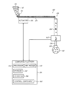
Reference is now made to Fig. 1, which shows a schematic illustration of an
apparatus for providing for dispensing predetermined number of items at high
accuracy and high efficiency.
The apparatus comprises a machine 100 communicating with and receiving
control commands from a computing platform 104. Machine 100 comprises a
counting
mechanism 140 which provides information to computing platform 104, upon which
control commands may be provided.
Machine 100 comprises a container, such as a hopper 112, which contains a
multiplicity of items 116 to be dispensed into containers. Each container,
such as
container 132, is to contain a predetermined number of items 116.
Hopper 112, shown here as one example of an item container, may comprise a
gate 114. Raising or lowering gate 114 limits the number of items 116 being
dispensed
from hopper 112 onto conveyor 120. In some embodiments, the level of gate 114
is
adjusted such that multiple items 116 can be dispensed onto conveyor 120
simultaneously or at partially overlapping time frames, so that there may be
no time
gap between the time frames at which two consecutive items exit hopper 112.
Handling multiple items concurrently provides for fast dispensing and high
yield of the
method and apparatus.
Conveyor 120 may be a conveyor belt, a vibrating chute, a chute having
variable
inclination angle or the like. Optionally, conveyor 120 is of a form
(hereinafter
"parallel transport conveyor") which enables transporting multiple items at
least
partially in parallel, in a direction orthogonal to the transport direction.
Conveyor 120 is controlled by actuator 124, which receives commands from
computing platform 104. Actuator 124 may operated by electrical current,
hydraulic
fluid pressure, pneumatic pressure or any other energy source, and converts
the energy
into some kind of motion applied to conveyor 120.
The functionality of actuator 124 depends on the nature of conveyor 120. For
example, if conveyor 120 is a conveyor belt, then actuator 124 drives or stops
the belt;
if conveyor 120 is a vibratory chute then actuator 124 starts or stops a
vibration
engine; if conveyor 120 is a variable inclination chute then actuator 124
lowers or
raises one side of the chute, or the like.
Items 116 proceed along or with conveyor 120 when operated, until the
conveyor's end 128. At =end 128, the items fall into container 132: In -some-
_..-
14
CA 02799058 2012-11-08
WO 2011/141919 PCT/IL2011/000383
embodiments, a hollow structure such as but not limited to a cylindrical pipe
136 goes
from end 128 or the vicinity thereof, to container 132 or the vicinity
thereof. Thus,
pipe 136 can be connected to any of end 128, container 132, both, or none. In
other
embodiments, pipe 136 may be eliminated, so that the items fall freely rather
than
within a limited space. In most situations where items are placed freely on
conveyor
120, most of the items at least partially overlap in a direction orthogonal to
the moving
direction of conveyor 120. In other words, items may be randomly arranged in
layers,
in parallel files and/or the like. This results in faster dispensing and a
higher yield of
the conveyor.
The falling items pass through counting mechanism 140 which may be integrated
into pipe 136. Alternatively, pipe 136 can be comprised of two parts, one part
going
from end 128 to counting mechanism 140, and the other part going from counting
mechanism 140 to container 132.
The item count as determined by counting mechanism 140 is transferred to
computing platform 104.
Counting mechanism 140 is further detailed in association with Fig. 3A and
Fig.
3B below.
Computing platform 104 may comprises a processor 144. Processor 144 may be
any Central Processing Unit (CPU), a microprocessor, an electronic circuit, an
Integrated Circuit (IC) or the like. Alternatively, computing platform can be
implemented as hardware or configurable hardware such as field programmable
gate
array (FPGA) or application specific integrated circuit (ASIC). In yet other
alternatives, processor 144 can be implemented as firmware written for or
ported to a
specific processor such as digital signal processor (DSP) or microcontrollers.
Processor 144 may be used for perfoming mathematical, logical or any other
instructions required by computing platform 104 or any of it subcomponents.
In some embodiments, computing platform 104 may comprise an MMI (man-
machine interface) module 148. MMI module 148 may be utilized for receiving
input
or providing output to and from machine 100, counting mechanism 140, or a
user, for
example receiving specific user commands or parameters related to calibrating
and
operating the apparatus, storing and retrieving information, providing output
for
analyzing performance of the apparatus, or the like.
In some exemplary embodiments, computing platform- 104 may comprise one or
CA 02799058 2012-11-08
WO 2011/141919 PCT/IL2011/000383
more storage devices such as storage device 152. Storage device 152 may be non-
transitory (non-volatile) or transitory (volatile). For example, storage
device 152 can
be a Flash disk, a Random Access Memory (RAM), a memory chip, an optical
storage
device such as a CD, a DVD, or a laser disk; a magnetic storage device such as
a tape,
a hard disk, storage area network (SAN), a network attached storage (NAS), or
others;
a semiconductor storage device such as Flash device, memory stick, or the
like. In
some exemplary embodiments, storage device 152 may retain program code of
control
component 160 detailed below operative to cause processor 144 to perform acts
associated with any of the steps of Fig. 2 detailed below, displaying
information to the
user, or the like. Storage device 152 may also retain information such as
calibration
results to be used when operating the machine for a particular type of
dispensing task,
number of finished containers, the number of items in each container, or the
like.
Computing platform 104 may further comprise or be associated with one or more
Input/Output (I/O) devices 156 such as a terminal, a display, a keyboard, an
input
device or the like, to interact with the system, to provide instructions for
calibrating the
machine or the like.
Computing platform 104 may execute control component 160 for determining
and generating control commands to be provided to actuator 124, optionally
during
calibration, and optionally during operation, for example in accordance with
counts
received from counting mechanism 140. Control component 160 can be implemented
as one or more sets of interrelated computer program instructions, which may
be
developed using any programming language and under any development
environment.
The computer program instructions may be stored on storage 152 and provided to
processor 144 or any other programmable processing apparatus to produce a
machine,
such that the instructions, which execute via the processor, create means for
implementing the functions specified in the flowcharts or block diagrams.
The computer program instructions may also be stored on a computer-readable
non-transitory medium to produce an article of manufacture. The steps
performed by
control component 160 are further detailed in association with Fig. 2 below.
It will be appreciated that computing platform 104 can be provided remotely
from machine 100, as part of machine 100, or in any combination thereof.
Referring now to Figs. 2A and 2B, showing a flowchart of steps in methods for
calibrating and operating a dispensing-machine, such as the one shown in Fig.
1, to
16
CA 02799058 2012-11-08
WO 2011/141919 PCT/IL2011/000383
provide high accuracy and high efficiency dispensing of items, thus yielding
high
throughput.
Fig. 2A shows a flowchart of steps in an embodiment of a calibrating stage 200
of a dispending machine.
On step 208, the conveyor is activated for a first duration. In some
embodiments,
the first time interval is long enough so as to reach substantially uniform
rate of falling
items, after the initial, incidental acceleration period (which typically
lasts a fraction of
a second) of the conveyor 120 has been completed.
On step 212, the number of items that have fallen into the container is
determined. The fallen items include also the items that have fallen due to
inertial
forces after the conveyor has stopped. It will be appreciated that step 212
can be
performed at least partially concurrently with step 208, since items may be
counted as
they fall, and/or after the conveyor has stopped.
On step 216, a first function is determined, which relates to the throughput
of the
system during activation, and associates a number of items falling during and
due to
the operation of the conveyor with the time period for which it is required to
operate
the conveyor. The first function may be described analytically, as a look-up
table, as a
part-wise function or in any other manner. It will be appreciated that the
first function
may or may not be substantially linear, wherein the non-linearity may be
mainly due to
the short, incidental acceleration and deceleration periods occurring when
activating
and stopping the conveyor.
On step 220, the conveyor is activated and operated for a second time
interval,
referred to as a pulse time interval, which is substantially shorter than the
first time
interval, typically lasting fractions of a second but optionally, in some
embodiments,
more than that. On step 224, the number of items to have fallen during and due
to said
operation is determined similarly to step 212 above. A pulse may relate to a
short time
interval in which the conveyor operates at its steady speed (or other
characteristic) for
a time period which is relatively short.
Steps 220 and 224 may be repeated one or more times, since the non-linearity
in
the throughput when activating the conveyor for short periods of time may be
high due
to the incidental acceleration and deceleration periods of the machine which
are long
relatively to the total pulse time.
On step- 228, a second- function is determined, which relates to the
throughput of
17
CA 02799058 2012-11-08
WO 2011/141919 PCT/IL2011/000383
the system in pulse activations. The function associates a number of items
falling
during and due to the activation of the conveyor with the time period for
which it is
required to activate the conveyor. The function may be described analytically,
as a
look-up table as a part-wise function or in any other manner.
In some embodiments, the first and second functions can be determined as a
single, possibly part-wise, function.
The first and second functions may be determined upon multiple activations
rather than a single activation each. Thus, the functions may be determined
statistically
while optionally employing analytical methods.
In some embodiments, the first and second functions are determined and later
used when the conveyor operates under constant characteristics, excluding on
the
acceleration and deceleration times, such as speed, vibration frequency,
vibration
amplitude, or the like.
Determining the first function, comprising steps 208, 212 and 216, and
determining the second function, comprising steps 220, 224 and 228, can be
performed
in reverse order.
It will also be appreciated that the first and second functions may be item-
and
setting-dependent, i.e., dispensing different items may yield different
functions. In
addition, other parameters of the machine may be determined, such as the
conveyor
speed, frequency, the height of the hopper gate, or the like.
Reference is now made to Fig. 2B, which shows a flowchart of steps in an
embodiment of a dispensing stage of a dispending machine.
On step 232, the conveyor is activated for a period of time determined such
that
the number of items falling due to activation approaches the number of items
it is
required to dispense in each container. The duration is determined in
accordance with
the first throughput function determined on step 216 of the calibration stage.
In some
embodiments, the period of time is determined such that in the majority of
cases, the
container will contain less than the required number of items. The reasoning
for that is
that it is generally more desirable, in this first operation of the conveyor,
to have fewer
items, which is correctable by adding items, than to have too many items
dispensed.
On step 236, the number of items that have fallen into the container is
determined. The number of items also includes the items that have fallen due
to inertial
forces after the conveyor has stopped. It will be appreciated that in some
embodiments
18
CA 02799058 2012-11-08
WO 2011/141919 PCT/IL2011/000383
the items are counted as they fall, which happens when the conveyor is in
motion and
some time afterwards.
On step 240, it is determined whether items are still missing in the container
to
complete the entire quantity that has to be dispensed.
If no items are missing, which may be a rare occasion, then on optional step
242,
the throughput functions or parameters thereof as set on calibration steps
200, such as
the values of particular points in the throughput functions, are updated based
on the
number of items that have fallen during the initial operation and the one or
more
pulses. Similarly, if the number of missing items becomes, in time, lower or
higher
than the number earlier set in the calibration step or in previous groups
dispensed, the
values of particular points in the throughput functions, are updated based on
the
number of items that have fallen during the initial operation and the one or
more
pulses. The updated parameters may be employed when dispensing further groups
of
items or in later activations. It will be appreciated that the on-the-fly
update of the
calibration parameters can be performed after dispensing items into one
container,
after a number of containers have been dispensed, after a full dispensing task
was
completed, or the like. Repeatedly updating the functions or parameters
enhances the
accuracy and thus the throughput of the method and apparatus.
Whether the calibration parameters have been updated on the fly or not, the
container is removed, and the next container is placed on step 244.
If items are still missing, then on step 248, the required duration is
determined
for a pulse length, such that the items that will fall due to the pulse will
approach or
complete the required number of items. The duration is determined in
accordance with
the second throughput function determined on step 228 on the calibration
stage.
In some embodiments, if the number or percentage of items missing in the
container exceeds a predetermined value, for example more than 10% or 10 items
of
the items are missing, the pulse length may be determined such that the total
number of
fallen items after the pulse may still not complete the required number in
many of the
cases and -another pulse may be required, which may provide higher accuracy.
Namely, if too many items are missing, then a single, long pulse may be
inaccurate and
inferior to a number of shorter pulses. If, however, the number of missing
items is
lower than the threshold, then the pulse length may be determined such that
the total
number of items after the pulsewill equal the required number:
19
CA 02799058 2012-11-08
WO 2011/141919 PCT/IL2011/000383
In alternative embodiments, only pulses of one or more predetermined lengths
may be enabled, such that if items are missing from the container, one of the
predetermined lengths can be selected. If only one such predetermined length
is
enabled, step 248 can be omitted.
Thus, on step 252 the conveyor may be activated for the determined or
predetermined pulse length.
On step 256 the number of fallen items is determined similarly to step 236
above,
and control returns to step 240.
Depending on the usage and nature of the items to be dispensed, in some
embodiments, a single activation of the conveyor would be enough to ensure
that in
large enough percentage of the cases, the number of dispensed items is within
satisfactory range from the required number. If, however, greater accuracy is
required,
then one or more pulses would be required to achieve the goal so that
overshooting is
as rare as possible. Overshooting, in general, may be related to the number of
items
that fall simultaneously into pipe 136 (Fig. 1). The width and/or structure of
conveyor
120 may be chosen so as to limit the number of items falling simultaneously
into pipe
136, for example the number may be limited to 3 items at most. In different
embodiments, depending on the type and/or size of the items, the number of
simultaneously-falling items which is limited by the width and/or structure of
the
conveyor may be different.
Reference is now made to Fig. 3A and Fig. 3B, showing an embodiment of
counting mechanism 140 of Fig. 1 and its mode of operation.
Fig. 3A shows an exemplary embodiment of a counting mechanism 140. The
mechanism comprises an arrangement of light sources and photo detectors
designed
for counting falling items. The items may be falling freely or inside a
bounded space
such as cylindrical pipe 136 of Fig. 1.
The arrangement can be arranged inside the pipe, between two disconnected
parts
of a pipe or around the falling area of the items.
The arrangement - comprises one or more, for example three sources of
electromagnetic energy 316, 320 and 324 such as laser diodes or other, and
three
receptors 336, 340, and 344 such as photo detectors sensitive to light or
another
electromagnetic energy. The sources and receptors are all located surrounding
the
falling area of the items; such as items 304, 308 and 312, and are-
substantially on one
CA 02799058 2012-11-08
WO 2011/141919 PCT/IL2011/000383
plane which is substantially orthogonal to the falling direction.
In some embodiments collimated light sources may be used, while in other
embodiments non-collimated light sources may be preferred.
In some embodiments, sources 316, 320 and 324 may be arranged so that the
energy is emitted from two or more of them in perpendicular directions. In
other
embodiments, all sources are arranged such that no two of them are
perpendicular. For
example, three sources can be arranged at angles of 60 as shown in Fig. 3A,
or 120
to one another.
It will be appreciated that light sources and photo detectors are exemplary
only,
and different technologies may be used for sensing the presence of objects.
When the dispensing apparatus is operated, each source emits energy which is
detected by the sensor located against it. Thus, the energy emitted by each of
sources
316, 320 and 324 is detected by a sensor located opposite to the source, e.g.,
sensors
336, 340 and 344, respectively.
When one or more items such as items 304, 308, 312 fall off end 128 of
conveyor 120 into container 132, the elements pass through counting mechanism
140,
and sensed by on one or more of the sensors.
In some embodiments, when light energy is emitted and sensed, light sources
316, 320 and 324 emit continuous light, and photo detectors 336, 340 and 344
are
sampled periodically. In other embodiments, sources 316, 320 and 324 emit
bursts of
light and 336, 340 and 344 are sampled respectively. The frequency of sampling
photo
detectors 336, 340 and 344 depends on the velocity of the falling items which
generally depends on the distance between falling end 128 and counting
mechanism
140, dictating how much gravitational acceleration has been achieved so far.
Photo
detectors 336, 340 and 344 have to be sampled at least once during each time
window
having duration equal to the time it takes an item to pass through the sensing
area, such
as through the light beams of sources 316, 320 and 324. Thus, it is guaranteed
that
each falling item will be captured at least once during the time it falls
through viewing
mechanism 140.. However,-if-the sampling frequency is higher, then-the-same
item-may
appear in multiple snapshots and may be counted more than once. This can be
substantially corrected by discarding, using image processing techniques,
items that
appear close to the top of one snapshot and close to the bottom of the next
snapshot.
Therefore, if it takes an item T 'milliseconds, to -fall through the light
beams of
21
CA 02799058 2012-11-08
WO 2011/141919 PCT/IL2011/000383
light sources 316, 320 and 324, the snapshots should be taken substantially
every T
milliseconds. In alternative embodiments, photo detectors 336, 340 and 344 may
be
implemented as CCD line detectors operating continuously at line frequencies
of
between about 5MHz and about 10MHz, wherein the images are constructed and
analyzed from the line scans.
Referring now to Fig. 4, showing an alternative embodiment to Fig. 3A, in
which
a light source 401 provides incoherent (optionally white) light. The light is
reflected
from items 304, 308 and 312 and is converged by lenses, such as lenses 416,
420 and
424, onto detectors 336, 340 and 344, respectively.
It will be appreciated that the counting mechanism can comprise additional
components, such as a cleaning mechanism for avoid obstructions in any of the
viewings connecting a source and a sensor. The cleaning mechanism can work,
for
example, by blowing air at high pressure, or the like.
Referring now to Fig. 3B, showing an example of three snapshots 348, 352 and
356, taken from sensors 336, 340 and 344, respectively, when items 304, 308
and 312
are falling through the counting mechanism. The shadows of items 304, 308 and
312
are indicated 304', 308' and 312', respectively.
Using image analysis techniques such as edge detection, items can be separated
within each snapshot. In the example of Fig. 3B, snapshot 348 shows three
distinct
items, snapshot 352 shows two distinct items and snapshot 356 also shows three
distinct items.
In some embodiments, the number of items falling at a specific time period may
be determined as the maximal number of items shown on any of the snapshots. In
the
example of Fig. 3B it would thus be determined that three items were falling,
as seen
in snapshot 348 or 356. In other exemplary embodiments, the number of falling
items
can be determined as the number of items shown in the majority of snapshots.
In the
example of Fig. 3B this would also yield a result that three items were
falling, as seen
in snapshot 348 and 356, while snapshot 352 shows only two items since item
308 is
hiding item- 304 -from the-point-of view- of source -320. It -would-be
appreciated-that
further methods can be utilized to determine the number of items that were
falling at
the time the snapshots were taken. It would also be appreciated that different
number
of sources and sensors can be used.
In some further analysis, image-analysis techniques may be- used for
determining
22
CA 02799058 2012-11-08
WO 2011/141919 PCT/IL2011/000383
whether a falling item is whole or broken, according to its various
projections on the
sensors. If this feature is provided, broken items can be either ignored or
removed from
the item stream so that the container will comprise at least the required
number of
proper items. Alternatively, the entire packaged unit 132 may be discarded.
In some embodiments, the analyzing of the snapshots and the determining of the
number of images is performed by a unit or module which constitutes a part of
counting mechanism 140. In other embodiments, the snapshots may be transferred
to
computing platform 104 or to any other computing platform for processing and
determining the number of falling items.
The above disclosure lays out a method and an apparatus for dispensing items,
optionally into containers, such that each container has a predetermined
number of
items. The method enables high accuracy so that exactly the required number of
items
is dispensed in high percentage of the cases. In instances where the number of
items
dispensed is not equal to the exact number required, it is guaranteed that the
number of
items exceeds and does not drop below the required number. Experimental
results have
shown that the disclosed method can account for providing the exact number of
items
in about 99.99% of the cases. The method also enables high efficiency and
throughput.
Since the items are not required to be provided from the hopper as a single
file, more
items can pass through the machine in each activation, thus providing higher
overall
dispensing rate.
While the disclosure has been described with reference to exemplary
embodiments, it will be understood by those skilled in the art that various
changes may
be made and equivalents may be substituted for elements thereof without
departing
from the scope of the disclosure. In addition, many modifications may be made
to
adapt a particular situation, material, step or component to the teachings
without
departing from the essential scope thereof. Therefore, it is intended that the
disclosed
subject matter not be limited to the particular embodiment disclosed as the
best mode
contemplated for carrying out this invention, but only by the claims that
follow.
In -the-description--and -claims of-the application,- each-of the-words-
"comprise"
"include" and "have", and forms thereof, are not necessarily limited to
members in a
list with which the words may be associated.
23