Note: Descriptions are shown in the official language in which they were submitted.
CA 02799551 2012-11-14
WO 2011/145965 PCT/RU2010/000246
METHODS FOR PROVIDING PROPPANT SLUGS IN FRACTURING
TREATMENTS
BACKGROUND
[00011 The
statements in this section merely provide background information related
to the present disclosure and may not constitute prior art.
[00021 In the
construction and development of wells formed in subterranean
formations, such as wells for the production of oil and gas, various
operations are carried
out that require the introduction of fluids of different types into the
wellbore and/or into
formation surrounding the wellbore.
100031
Hydraulic fracturing is one such operation conducted in wells that is used to
increase the production of fluids from the subterranean formations. Hydraulic
fracturing
involves introducing fluids into the wellbore at very high flow rates and
pressures to
facilitate cracking and fracturing of the surrounding formation. The
fracturing fluid
injection rate exceeds the Filtration rate into the formation so that the
pressure increases at
the rock face. Once the pressure exceeds the fracturing pressure threshold of
the rock,
the formation cracks and the fracture begins to propagate as the injection of
the fracturing
fluid continues.
[00041 In
hydraulic fracturing, generally a proppant is introduced into the formation
with the fracturing fluids at certain stages of the fracturing operation.
Typically, the
proppant is admixed with the fracturing fluid continuously during the
treatment. The
proppant (e.g. sand) is deposited in the formed fractures of the formation so
the proppant
prevents the fracture from closing when the pressure is reduced. This allows
reservoir
fluids to flow from the formation through the fractures to the kvellbore so
that they can be
produced. Various methods exist for fracturing such formations.
100051
Recently, techniques have been developed to provide heterogeneous proppant
placement in the fracture. While heterogeneous proppant placement in hydraulic
fracturing is known, methods of providing proppant slugs in fracturing fluids
to provide
CA 02799551 2012-11-14
WO 2011/145965 PCT/RU2010/000246
heterogeneous proppant placement within the fractures of the formation are
still in need
of development.
100061 SUMMARY
100071 A proppant pack is placed into a fracture that extends from a
wellbore formed
in a subterranean formation. This is accomplished by performing different
operations
that facilitate providing multiple spaced apart proppant slugs within a
hydraulic
fracturing fluid that is introduced into the wellbore at a pressure above the
fracturing
pressure of the formation.
[0008] In one operation a hopper containing proppant is provided haying a
controllable metering unit that can be opened and closed between closed and
variable
open positions. The metering unit selectively meters proppant from the hopper
to a
variable speed conveyer in discrete, spaced apart proppant groups. The
proppant groups
are delivered by the conveyer to a mixing tank where the proppant is combined
with the
hydraulic fracturing fluid. The size and spacing of the proppant groups is
controlled by a
combination of the metering unit and the speed of the variable speed conveyor.
[0009] In another operation, proppant is provided to a variable speed
rotating auger
conveyor. The auger conveyor has a discharge that discharges conveyed proppant
to a
mixing tank. The auger is rotated and stopped at intervals to provide discrete
proppant
groups that are discharged to the mixing tank.
1001(11 The multiple spaced apart proppant slugs may also created by
providing a pre-
mixed proppant slurry and a clean fluid that form the fracturing fluid and at
least one of
a) alternating the flow of the pre-mixed proppant slurry and the clean fluid
and b) pulsing
one of the pre-mixed proppant slurry and clean fluid into the other. The pre-
mixed
proppant slurry and the clean fluid may each be pumped through different pumps
or
through the same pump.
[0011] The at least one of a) alternating the flow of the pre-mixed
proppant slurry and
the clean fluid and b) pulsing one of the pre-mixed proppant slurry and clean
fluid into
the other may also be accomplished by the use of one or more control valves,
which may
include a back pressure regulator valve. The back pressure regulator valve may
be used
with each of the pre-mixed proppant slurry and the clean fluid to facilitate
the at least one
CA 02799551 2012-11-14
WO 2011/145965 PCT/RU2010/000246
3
of a) alternating the flow of the pre-mixed proppant slurry and the clean
fluid and b)
pulsing one of the .pre-mixed proppant slurry and clean fluid into the other.
The back
pressure regulator valve may be used with one of the pre-mixed proppant slurry
and the
clean fluid and a non-back pressure regulator valve may be used with the other
the fluid
to facilitate the at least one of a) alternating the flow of the pre-mixed
proppant slurry and
the clean fluid and b) pulsing one of the pre-mixed proppant slurry and clean
fluid into
the other.
100121 In other embodiments, the at least one of a) alternating the flow of
the pre- -
mixed proppant slurry and the clean fluid and b) pulsimg one of the pre-mixed
proppant
slurry and clean fluid into the other may be accomplished by the use of a
three-way
valve. The three-way valve may include a valve housing having, at least two
now
passages, with each flow passage allowim1 the passage of one of the proppant
slurry and
the clean slurry. A valve closure of the three-way valve may rotate about an
axis
substantially parallel to the fluid flow through the passat!es to selectively
close the fluid
passages.
[00131 In other embodiments, diluted proppant slurry is introduced into an
inlet of a
hydrocylone separator. The hydrocyclone separator has an underflow outlet and
overflow outlet wherein the pre-mixed proppant slurry is provided from at
least one of
the underflow outlet and overflow outlet. The clean fluid may be formed from
the diluted
proppant slurry and the multiple spaced apart proppant slugs are provided by
controlling
the flow of fluid through at least one of the underflow outlet and the
overflow outlet. In
another embodiment, the pre-mixed proppant slurry may be delivered by a piston
pump.
100141 In one embodiment, a proppant. pack is placed into a fracture that
extends
from a wellbore formed in a subterranean formation by providing a proppant in
a pre-
mixed proppant slurry and a clean fluid that form the fracturing fluid. The
method
requires at least one of a) alternating the flow of the pre-mixed proppant
slurry and the
clean fluid and b) pulsing one of the pre-mixed proppant slurry and clean
fluid into the
other to facilitate providing multiple spaced apart proppant slugs within a
hydraulic
fracturing fluid that is introduced into the wellbore at a pressure above the
fracturing:
pressure of the formation.
CA 02799551 2016-10-03
54138-209
4
[0015] In another embodiment, a method of fracturing a subterranean
formation is
presented that involves pumping a hydraulic fracturing fluid at sufficient
pressure to fracture
the subterranean formation, the fracturing fluid comprising multiple proppant
slugs spaced
apart. The propant slugs may be generated by providing a hopper containing
proppant having
a metering unit that selectively meters proppant from the hopper to a conveyor
for delivery in
discrete, spaced apart proppant groups to a mixing tank where the proppant is
combined with
the hydraulic fracturing fluid. The proppant slugs may be generated by a
rotating auger
conveyor, the auger conveyor having a discharge that discharges conveyed
proppant to a
mixing tank, the auger being rotated and fully stopped at intervals to provide
discrete proppant
groups that are discharged to the mixing tank. The proppant slugs may be
provided by
alternating the flow of the pre-mixed proppant slurry and the clean fluid or
pulsing one of the
pre-mixed proppant slurry and clean fluid into the other.
[0015a] In another embodiment, there is provided a method of placing a
proppant pack
into a fracture that extends from a wellbore formed in a subterranean
formation, the method
comprising: performing at least one of the following to facilitate providing
multiple spaced
apart proppant slugs within a hydraulic fracturing fluid that is introduced
into the wellbore at a
pressure above the fracturing pressure of the formation: (1) providing a
hopper containing
proppant having a controllable metering unit that can be opened and closed
between closed
and variable open positions, the metering unit selectively metering proppant
from the hopper
to a conveyer in discrete, spaced apart proppant groups, the proppant groups
being delivered
by the conveyer to a mixing tank where the proppant is combined with the
hydraulic
fracturing fluid, and wherein the size and spacing of the proppant groups is
controlled by a
combination of the metering unit and the speed of the conveyor; (2) providing
proppant to a
variable speed rotating auger conveyor, the auger conveyor having a discharge
that discharges
conveyed proppant to a mixing tank, the auger being rotated and fully stopped
at intervals to
provide discrete proppant groups that are discharged to the mixing tank; and
(3) providing a
proppant in a pre-mixed proppant slurry and a clean fluid that form the
fracturing fluid and
pulsing one of the pre-mixed proppant slurry and clean fluid into the other;
forming high
concentration pre-mixed proppant slurries by using hydrocyclones; wherein the
pulsing one of
CA 02799551 2016-10-03
=
54138-209
4a
the pre-mixed proppant slurry and clean fluid into the other is accomplished
by the use of a
three-way valve.
[0015b] In another embodiment, there is provided a method of placing a
proppant pack
into a fracture that extends from a wellbore formed in a subterranean
formation, the method
comprising: providing a proppant in a pre-mixed proppant slurry and a clean
fluid that form
the fracturing fluid and pulsing one of the pre-mixed proppant slurry and
clean fluid into the
other to facilitate providing multiple spaced apart proppant slugs within a
hydraulic fracturing
fluid that is introduced into the wellbore at a pressure above the fracturing
pressure of the
formation; forming high concentration pre-mixed proppant slurries by using
hydrocyclones;
wherein the pulsing one of the pre-mixed proppant slurry and clean fluid into
the other is
accomplished by the use of a three-way valve.
[0015c] In another embodiment, there is provided a method of fracturing a
subterranean
formation comprising: pumping at sufficient pressure to fracture the
subterranean formation a
fracturing fluid comprising multiple proppant slugs spaced apart, wherein the
proppant slugs
are provided by performing at least one of: (1) providing a hopper containing
proppant having
a controllable metering unit that can be opened and closed between closed and
variable open
positions, the metering unit selectively metering proppant from the hopper to
a conveyer in
discrete, spaced apart proppant groups, the proppant groups being delivered by
the conveyer
to a mixing tank where the proppant is combined with the hydraulic fracturing
fluid, and
wherein the size and spacing of the proppant groups is controlled by a
combination of the
metering unit and the speed of the conveyor; (2) providing proppant to a
variable speed
rotating auger conveyor, the auger conveyor having a discharge that discharges
conveyed
proppant to a mixing tank, the auger being rotated and fully stopped at
intervals to provide
discrete proppant groups that are discharged to the mixing tank; and (3)
providing a proppant
in a pre-mixed proppant slurry and a clean fluid that form the fracturing
fluid and pulsing one
of the pre-mixed proppant slurry and clean fluid into the other; forming high
concentration
pre-mixed proppant slurries by using hydrocyclones; wherein the pulsing one of
the pre-
mixed proppant slurry and clean fluid into the other is accomplished by the
use of a three-way
valve.
CA 02799551 2016-10-03
54138-209
4b
BRIEF DESCRIPTION OF THE DRAWINGS
[0016] For a more complete understanding of the present invention, and
the
advantages thereof, reference is now made to the following descriptions taken
in conjunction
with the accompanying figures, in which:
[0017] FIGURE 1 is a plot of actual proppant slug concentration
contrasted with an
ideal target proppant slug concentration according to a given pumping
schedule;
[0018] FIGURE 2 is a schematic of a proppant feed system utilizing a
propant hopper
and metering system in conjunction with a conveyor for delivering proppant in
pulses in a
fracturing fluid;
[0019] FIGURE 3 is a schematic of an auger conveyor proppant feeding
system for
delivering proppant in pulses in a fracturing fluid;
[0020] FIGURE 4 is a schematic of a pumping system for pumping
alternating
proppant-laden and clean fluids to a wellhead using control valves to form
proppant slugs;
[0021] FIGURE 5 is a schematic of a pumping system for pumping
alternating
proppant-laden and clean fluids to a wellhead using separate pumps to form
proppant slugs;
CA 02799551 2012-11-14
WO 2011/145965 PCT/RU2010/000246
100221 FIGURE 6 is a schematic of a pumping system for pumping alternating
proppant-laden and clean fluids to a wellhead using back pressure regulator
control
valves with both the proppant-laden and clean fluids to form proppant slugs;
[0023] FIGURE 7 is a schematic of a pumping system for pumping alternating
proppant-laden and clean fluids to a wellhead using a back pressure regulator
control
valve with one of the proppant-laden fluid and clean fluids and a check valve
used with
the other fluid to form proppant slugs;
100241 FIGURE 8 is a schematic of a pumping system for pumping alternating
proppant-laden and clean fluids to a wellhead using a three-way valve with one
of the
proppant-laden fluid and clean fluids and a check valve used with the other
fluid to form
pro ppa nt slugs;
[0025] FIGURE 9 is a schematic ol'a three-way valve that may be used with
pumping
system of Figure 8;
100261 FIGURE 10 is a perspective view of a three-way valve configured for
use
with the pumping system of Figure 8; and
[0027] FIGURE I 1 is a schematic of a hydrocyclone separator for use in
providing a
proppant-laden
DETAILED DESCRIPTION
100281 The description and examples are presented solely for the purpose of
illustrating the different embodiments of the invention and should not be
construed as a
limitation to the scope and applicability of the invention. While any
compositions of the
present invention may be described herein as comprising, certain materials, it
should be
understood that the composition could optionally comprise two or more
chemically
different materials. In addition, the composition can also comprise some
components
other than the ones already cited. While the invention may be described in
terms of
treatment of vertical wells, it is equally applicable to wells of any
orientation. The
invention will be described for hydrocarbon production wells, but it is to be
understood
that the invention may be used for wells for production of other fluids, such
as water or
carbon dioxide, or, for example, for injection or storage wells. It
should also be
understood that throughout this specification, when a concentration or amount
range is
CA 02799551 2016-10-03
54138-209
6
described as being useful, or suitable, or the like, it is intended that any
and every
concentration or amount within the ranee, including the end points, is to be
considered as
having been stated. Furthermore, each numerical value should be read once as
modified
by the term "about" (unless already expressly so modified) and then read again
as not to
be so modified unless otherwise stated in context. For example, "a range of
from I to
10" is to be read as indicating each and every possible number along the
continuum
. between about 1 and about 10. In other words, when a certain range is
expressed, even if
only a few specific data points are explicitly identified or referred to
within the range, or
even when no data points are referred to within the range, it is to be
understood that the
inventors appreciate and understand that any and all data points within the
range are to be
considered to have been specified, and that the inventors have possession of'
the entire
range and all points within the range.
100291
Heterogeneous proppant placement within fractures of a subterranean
formation may be provided by pumping alternate stages of' proppant-laden and
clean or
proppant-free fluids. This can be accomplished by controlling the delivery of
proppant
so that it is integrated into the fracturing fluid at the surface and thereby
forms proppant
slugs to facilitate heterogeneous proppant placement within the fractures when
introduced
into the formation. Examples of such heterogeneous proppant placement are
described in
U.S. Patent Nos. 7,451,812 and 7,581,590 and in International Publication No.
W02009/005387.
100301 As used
herein, the expression "clean fluid" or similar expressions is meant
to encompass a fluid that is substantially free of proppant or that may have a
significantly
lower amount or concentration of' proppant than a proppant slurry. Likewise,
the
expression "proppant slurry" or "proppant-laden fluid" is meant to encompass a
fluid that
contains a significant amount of proppant to facilitate formation of a
proppant slug. The
concentration of proppant for the proppant slug is always higher than for the
proppant
concentration of the adjacent clean fluid slug and may be from 5, 10, 20,50 or
100 times
higher or more than the proppant concentration of the clean fluid, when the
clean fluid
contains an amount of' proppant.
CA 02799551 2012-11-14
WO 2011/145965 PCT/RU2010/000246
7
100311 In conventional viscosified hydraulic fracturing fluids, the clean
fluid may
have proppant in an amount of from 0 to about 2 pounds per gallon (PPA) of
fluid or
from 0 to about 0.24 kg/L. In contrast, the proppant slug for a hydraulic
fracturing fluid
may contain proppant in an amount of from about 0.1 PPA (0.01 kg/L) to about
20 PPA
(2.4 kg/L) or more. Typically, the proppant slug vill have a proppant
concentration of
from about 1 PPA (0.12 kg/L) to about 12 PPA (1.4 kg/L). In other fracturing
fluids,
such as thin water or slick-water fluids that are used in treating tight shale
formations
where the fluid contains little or no polymer or viscosifying agent, the clean
fluid may
have a proppant concentration of 0 to about 0.1 PPA (0.1 kg/L), with the
proppant slug
having a proppant concentration of from about 0.1 PPA (0.1 kg/L) to about 2
PPA (0.24
kg/L). The proppant materials may be construed to be any particulate materials
that are
introduced into a fracture to facilitate keeping the fracture open. The term
"proppant" is
intended to include sand, gravel, glass beads, polymer beads, ground products
from shells
and seeds such as walnut hulls, manmade materials such as ceramic proppant in
this
discussion. The proppant may be coated with, for example, resin, adhesive, or
tackifier
coating. In general the proppant used may have an average particle size of
from about
0.15 mm to about 2.5 mm. more particularly. but not limited to typical size
ranges of
about 0.25-0.43 mm, 0.43-0.85 mm, 0.85-1.18 mm, 1.18-1.70 mm, and 1.70-2.36
mm.
100321 The proppant particles may be substantially insoluble in the fluids
of the
formation. Any proppant can be used, provided that it is compatible with the
formation,
the fluid, and the desired results of the treatment. The proppants may be
natural or
synthetic, coated, or contain chemicals; more than one type of proppant can be
used
sequentially or in mixtures and the proppant particles may be of different
sizes or
different materials. Proppants and gravels in the same or different wells or
treatments
can be the same material and/or the same size as one another. The proppant may
be
selected based on the rock strength, injection pressures, types of injection
fluids, or even
completion design. The proppant materials may include, but are not limited to,
sand,
sintered bauxite, glass beads, ceramic materials, naturally occurring
materials, or similar
materials. Naturally occurring materials may be underived and/or unprocessed
naturally
occurring materials, as well as materials based on naturally occurring
materials that have
CA 02799551 2016-10-03
54138-209
8
been processed and/or derived. Suitable examples of naturally occurring
particulate
materials for use as proppants include, but are not necessarily limited to:
ground or
crushed shells of nuts such as walnut, coconut, pecan, almond, ivory nut,
brazil nut, etc.;
ground or crushed seed shells (including fruit pits) of seeds of fruits such
as plum, olive,
peach, cherry, apricot, etc.; ground or crushed seed shells of other plants
such as maize
(e.g., corn cobs or corn kernels), etc.; processed wood materials such as
those derived
from woods such as oak, hickory, walnut, poplar, mahogany, etc., including,
such woods
that have been processed by grinding, chipping, or other form of
particalization,
processing, etc. Further information on some of the above-noted compositions
thereof
may be found in Encyclopedia of Chemical Technology, Edited by Raymond E Kirk
and
Donald F. Othmer, Third Edition, John Wiley & Sons, Volume 16, pages 248-273
(entitled "Nuts"), Copyright 1981. In certain embodiments, the proppant may be
formed from non-fly ash materials.
100331 All or some of the proppant materials may be provided with
adhesive
properties as well, which may be added at a manufacturing facility or on the
fly while
being mixed with treatment fluids at the wellsite. The adhesive properties may
be
provided by a coating, such as resin coating, that is added at a manufacturing
facility or
on the fly while being mixed with treatment fluids at the wellsite. The
adhesive properties
may be provided by a resin coating. The resins used may include, for example,
epoxy,
phenolic (e.g. phenol formaldehyde), polyurethane elastomers, amino resins,
polyester
resins, acrylic resins, etc. Examples of resin coated particles are described
in U.S. Patent
Nos. 3,929,191, 4,585,064 and 5,422,183. The coating thickness my vary, but
resin
coatings that makeup of from about 1 to about 99% by total weight of resin
coated
proppant (RCP) may be used, more particularly from about 1 to about 50% by
total
weight of RCP.
100341 The resin coated proppants may be coated particles where the
resin is initially
uncured when the proppant slurry is initially formed. The non-cured ( often
referred to as
curable) RCP may initially be generally solid and nontacky at surface
conditions, thus
facilitating handling and preparation of the proppant slurry, as the proppant
particles do
not tend to stick together. Upon introduction into the fracture in the
subterranean
CA 02799551 2012-11-14
WO 2011/145965 PCT/RU2010/000246
9
formation, the resin will soften due to the higher temperatures encountered.
Subsequently, the resin cures or crosslinks so that it becomes hard and
infusible, with
some flexibility. Typical temperatures that facilitate curing range from about
40 C to
about 250 C. At lower temperatures, i.e. temperatures of less than about 60
C, curing
aids may be used to provide sufficient consolidation within a reasonable
length of time.
Such curing aids are known by those skilled in the art and may include, for
example,
isopropanol, methanol and surfactants with alcoholic compounds.
100351 Curing, or crosslinking of the resin may occur merely due to
heating. The
resin may be selected so that curing occurs at particular temperatures and so
that certain
time periods may be required for curing to ensure that the resin does not cure
too quickly.
Resins having cure times of from about 1 hour to about 75 hours or more may be
used to
ensure that sufficient time is allowed for positioning of the proppant pack.
100361 Pre-cured resin coated proppants includes those resin coated
proppant
particles where the resin has been at least partially cured or crosslinked at
the surface
prior to introduction into the yell or fracture. Such pre-cured RCP may be
particularly
useful \vith fracturing fluids because they do not require temperature for
activation. The
pre-cured resin coated proppant particles may only interact physically with
each other.
with no chemical bonding. As a result, a thicker resin coating may be required
compared
to uncured RCP. The coatings used may be flexible ones that can be easily
deformed
under pressure. This coupled with thicker coating on the proppant surface may
give rise
to stronger interactions between particles. Such materials included rubbers,
elastomers,
thermal plastics or plastics. The adhesive material of the proppant materials
may facilitate
aggregation of the proppant materials. The proppant may also have self-
aggregation
properties. In certain embodiments, an adhesive material may be added that
wets or coats
the proppant materials. The proppant used comprise a single type of proppant
or a
mixture of more than one type of proppant with varied properties. Proppant
properties
that may be varied include for example density, mesh size, shape or geometry,
chemical
composition, and uniformity. Mixtures of proppant type, property, or size may
be
selected for particular wellbore conditions or reservoir properties.
CA 02799551 2012-11-14
WO 2011/145965
PCT/RU2010/000246
100371
Examples of suitable commercially available non-cured resin coated particles
include Super HS, Super LC, Super TF, Super HT, MagnaProp, DynaProp, Opti Prop
and
PolaProp, all available from Santrol, Inc., Fresno, California and Ceramax
resin coated
proppants, available from Borden Chemical, Columbus, Ohio. The resin coated
particles
may also include particles having a tackifying or similar coating that
provides similar
characteristics to the RCP previously described, such as the coated sand,
which may be
added on the fly to the proppant slurry.
Alternatively, chemical coatings to provide
desired properties, such as tackiness, adhesion, or variable wettability may
be added to
the proppant 00 the fly.
100381 The
fracturing fluids and systems used for carrying out the hydraulic
fracturing are typically aqueous fluids, but could also include fluids made
from a
hydrocarbon base or emulsion fluid. The fracturing fluids could he foamed or
emulsified
using nitrogen or carbon dioxide. The aqueous fluid may include fresh water,
sea water.
salt solutions or brines. The aqueous fluids for both the proppant slurry and
the clean
fluid are typically viscosified so that they have sufficient viscosities to
carry or suspend
the proppant materials, prevent fluid leak off, etc. In order to provide the
higher viscosity
to the aqueous fracturing fluids, water soluble or hydratable polymers are
()hen added to
the fluid. These
polymers may include, but are not limited to, guar gums, high-
molecular weight polysaccharides composed of mannose and galactose sugars, or
guar
derivatives such as hydropropyl guar (HPG), carboxymethyl guar (CMG), and
carboxymethvIhydroxypropyl guar (CMHPG). Cellulose derivatives such as
hydroxyethylcellulose (HEC) or hydroxypropylcel lu lose (HPC)
and
carboxymethylhydroxyethylcellulose (CMHEC) may also be used. Any useful
polymer
may be used in either crosslinked form, or without crosslinker in linear form.
Xanthan,
diutan, and scleroglucan, three biopolymers, have been shown to be useful as
viscosifying agents. Synthetic polymers such as, but not limited to,
polyacrylamide and
polyacrylate polymers and copolymers are used typically for high-temperature
applications or for the purpose of providing friction reduction.
[00391 In
some embodiments of the invention, a viscoelastic surfactant (VES) is used
as the viscosifying agent for the aqueous fluids. The VES may be selected from
the
CA 02799551 2016-10-03
54138-209
ii
group consisting of cationic, anionic, zwitterionic, amphoteric, nonionic and
combinations thereof. Some nonlimiting examples are those
cited in U.S. Patent Nos. 6,435,277 and 6,703,352. The
viscoelastic surfactants, When used alone or in combination, are capable of
forming
micelles that form a structure in an aqueous environment that contribute to
the increased
viscosity of the fluid (also referred to as "viscosifying micelles"). These
fluids are
normally prepared by mixing in appropriate amounts of VES suitable to achieve
the
desired viscosity. The viscosity of VES fluids may be attributed to the three
dimensional
structure formed by the components in the fluids. When the concentration of
surfactants
in a viscoelastic fluid significantly exceeds a critical concentration, and in
most cases in
the presence of an electrolyte, surfactant molecules aggregate into species
such as
micelles, which can interact to form a network exhibiting viscous and elastic
behavior.
100401 The
fluids may also contain a as component. The gas component may be
provided from any suitable gas that forms an energized fluid or foam when
introduced
into the aqueous medium. See, for example, U.S. Pat. No. 3,937,283 (Blauer et
al.).
.The gas component may comprise a gas selected from
nitrogen, air, argon, carbon dioxide, and any mixtures thereof. Particularly
useful are the
gas components of nitrogen or carbon dioxide, in any quality readily
available. The
treatment fluid may contain from about 10% to about 90% volume gas component
based
upon total fluid volume percent. more particularly from about 20% to about SO%
volume
gas component based upon total fluid volume percent, and more particularly
from about
30% to about 70% volume gas component based upon total fluid volume percent.
[00411 In
certain embodiments, the treatment fluid may be used in fracturing tight or
low-permeable formations, such as tight shale; carbonate, sandstone and mixed
formations. Such formations may have a permeability of from about 1 mD or 0.5
mD or
less. In such fracturing operations, water, which may be combined with a
friction
reducing agent in the case of slickwater, is introduced into the formation at
a high rate to
facilitate fracturing the formation. Often, polyacrylamides are used as the
friction-
reducing polymer. These fracturing fluids may use lighter weight and
significantly lower
amounts of proppant than conventional viscosified fracturing fluids. In
water or
CA 02799551 2012-11-14
WO 2011/145965 PCT/RU2010/000246
12
slickwater fracturing, the proppant slurry may contain from about 0.1 PPA
(0.01 kg/L) to
about 2 PPA (0.24 kg/L) or proppant, with the clean fluid containing- from 0
to 0.1 PPA
(0.01 kg/L) proppant. The high pumping: or flow rate of these fluids may also
facilitate
the suspension of the proppant materials. The water used for such fracturing,
treatments
may be formed from fresh water, sea water, brine or a salt solution.
100421 To
provide the most effective heterogeneous proppant placement, it is
beneficial to create a proppant pulse or slug with as ideal a shape as
possible. The ideal
shape of a proppant slug or pulse is considered to be that having a
concentration with
sharp front and hack edges, as shown by the squared proppant pulses indicated
at A of
Figure I. which illustrates an ideal proppant concentration target. In
actuality, the
proppant slug or pulse concentrations may not meet that target, as shown by
the proppant
profile B, due to an inadequate proppant feeding system and proppant inertia.
It is known
that a proppant feeding system cannot start or stop immediately, which creates
a transient
region in proppant concentration (i.e. non-ideal shape of the proppant pulse).
Therefore,
the transient time of starting and stopping of proppant feeding should be
minimized.
[00431 In
order to create the heterogeneous proppant placement within fractures of a
subterranean formation, alternate stages of proppant-laden and clean or
proppant-free
fluids are created at the surface with as little transient time of starting
and stopping of the
proppant feeding as possible prior to introduction of the fracturing fluid
into the wellhead
of the wellhore. Referring to Figure 2, in a first embodiment, the alternating
proppant-
laden and clean fluid slugs may be formed by providing a proppant hopper or
other
storage unit 10 having an outlet to which the proppant is fed, such as through
gravity
feed. The delivery of proppant from the hopper outlet is metered or controlled
with a
metering unit or valve 12 to a conveyor 14. As used herein, a metering unit
includes any
device that is capable of regulating the flow of proppant from a storage unit
or area into
the fracturing fluid. A metering unit may be controlled by a variety of
methods ranging
from manual operation to semi-automatic operation to fully-automated
activation using
an overall control process. The metering unit 12 may be a hopper gate, star
feeder, valve
or other device that provides controlled quantities of proppant to be
dispensed from the
hopper 10. The metering unit 12 may provide variable metering wherein
different
CA 02799551 2012-11-14
WO 2011/145965 PCT/RU2010/000246
13
amounts of proppant are metered when the metering unit 12 is between a fully
open and a
fully closed position. The
metering unit 12 and conveyor 14 may be remotely
controlled.
[0044j The
conveyor 14 may be a belt conveyor or other conveyor that may be
operable at various speeds and be controllable so that it can be started and
stopped as
necessary to facilitate control of proppant delivery. The
proppant groups are delivered
by the conveyor 14 as indicated by arrow 16 to one or more mixing tanks 18
where the
proppant is combined and mixed with a clean hydraulic fracturing fluid 20. The
fracturing fluid is continuously delivered from the mixing tank 18 to the
wellhead 22
where it is introduced into the formation. By utilizing the combination of the
metering
unit 12 and a conveyor 14, the proppant can be delivered from the hopper in
discrete,
spaced apart proppant groups to the mixing tank. A controllable variable speed
conveyor
14 may be used. It should be apparent that the system of Figure 2 is
simplified and other
equipment and components, such as pumps, additive streams, etc. would also be
incorporated. As can be seen, the size and spacing of the proppant groups is
controlled
by a combination of the metering unit 12 and the speed conveyor 14. In certain
cases,
the metering from the hopper 10 may be constant or may he varied, with
different
amounts of proppant being metered and the tulle between each metering event
being
different. In
certain embodiments. the timing between opening and closing of the
metering unit 12 may be 5 seconds or less, but may also be longer.
Additionally, the
metering events from the hopper 10 may remain generally constant but the speed
of the
conveyor may be varied, started and stopped. Other combinations employing the
hopper
metering and the conveyor speed and starts and stops may be used.
100451
Referring to Figure 3, an alternate embodiment of a proppant delivery system
is shown that utilizes an auger conveyor 24, with similar components to those
of Figure 2
being labeled with the same reference numerals. The auger conveyor 24 is a
variable
speed rotating or screw-type auger conveyor that can be operated at various
speeds and
repeatedly stopped and started. The auger 24 may be horizontal or tilted and
may have a
sufficient capacity to provide the desired amount of proppant based upon the
pumping
rate and the desired amount of proppant needed for each stage. The auger
conveyor 24
CA 02799551 2012-11-14
WO 2011/145965 PCT/RU2010/000246
14
has an outlet or discharge that discharges conveyed proppant to the mixing
tank 18 where
it is combined with clean fracturing fluid 20, the auger being rotated and
fully stopped at
intervals to provide discrete proppant groups that are discharged to the
mixing tank 18.
The auger 24 may be started and stopped at intervals of from 5 seconds or
less. In certain
embodiments more than one auger conveyor may be used to feed proppant. By
alternating starting and stopping of the auger 24, proppant and clean stages
of fracturing
fluid are created that flow from the mixing tank 18 and are delivered to the
wellhead 22.
In certain embodiments, the auger 24 may be combined with the embodiment of
Figure 2,
\\herein proppant is delivered to the auger 24 by the hopper 10 using a
metering unit I2.
[00461 In a typical fracturing operation, the fracturing fluid may be
pumped at a flow
rate of from about 5 to 200 barrels (bbl) per min (0.79 m to 31.80 m" per
min). In
typical hydraulic fracturing operations, the pumping rate may be from about 5
to about 50
bbl/min (0.79 to 7.95 m3/min). In fracturing shale or tight formations. the
water or
slid:water may be pumped at a higher rate of from about 50 to about 150 or 200
bbl/min
(7.95 to 23.85 or 31.80 m3/min). In providing the alternating proppant slug
and clean
fluid stages using the systems of Figures 2 and 3 and other systems described
herein, the
proppant is delivered to or with the fracturing fluid TO provide alternating
proppant and
clean fluid stages that have a duration of less than 60 seconds each at the
given fracturing
treatment pumping rate. In certain embodiments, the proppant is delivered to
provide a
proppant stage that is 40 seconds or less. In some embodiments, the proppant
stage may
have durations of 30 to 40 seconds, 20 to 30 seconds, 10 to 20 seconds and 5
to 10
seconds. In certain embodiments, the proppant delivery may provide a duration
of less
than 5 seconds at the given pump rate. Such a short duration may facilitate
the creation
of proppant pulses that are as close as possible to the ideal proppant pulse
A. as is shown
in Figure 1. The duration of the proppant stages may range from greater than
0% to 10%,
15%, 20%, 25% or 30% of the duration of the clean fluid stages. As an example,
employing the system of Figure 2, at a pumping rate of 20 bbl/min (3.18
m"/min) the
metering unit may be open 5 seconds to meter proppant and then closed for 15
seconds
with a generally constant conveyor speed. This may be repeated. The number of
cycles
CA 02799551 2012-11-14
WO 2011/145965 PCT/RU2010/000246
of alternating clean and proppant stages may range from about 10 to about a
few
thousand (e.g., 2000) cycles or more for a fracturing treatment.
100471 For
the embodiments of Figures 2 and 3, the proppant feeding system may
require calibration of the equipment because of non-ideal proppant pulse
shapes, as
shown in Figure I. Calibration or recalibration may be conducted by proppant
totalization and comparison with the proppant amount according to a schedule.
Thus, for
example, if less proppant is pumped than expected, the amount of proppant
metered
maybe increased. Correction coefficients for gate position, belt speed or
auger rotation
speed may be calculated based upon the calibration. The correction coefficient
may
differ for different proppant concentrations. For example, the term K-factor
is used to
refer to the conversion of drive revolutions (such as auger rotations) to the
calculated
fluid rate. The higher the proppant concentration the closer are K-factors of
pulse regime
to K-factors of conventional continuously feeding proppant regimes. At lower
proppant
concentrations, greater adjustments to the K-factor may be useful to calibrate
amount of
proppant calculated to the amount of proppant pumped.
100481 In
other embodiments, proppant pulses are provided by utilizing a pre-mixed
proppant slurry along with a clean fluid. Referring to Figure 4. an
illustration of one such
embodiment is shown. In this embodiment, a clean fluid from a tank or clean
fluid
supply I. which may be a pre-mixed fracturing fluid, is alternated with a pre-
mixed
proppant slurry from proppant slurry tank or supply 2 is delivered by one or
more high
pressure pumps 3 to the wellhead 4. The
fluids used for the clean and pre-mixed
proppant slurries may be the same or different. For example, if different, the
different
fluids may contain different additives or different relative amounts. One of
the fluids
may be erosslinked while the other mav be linear, the clean fluid may be a
foam while the
proppant fluid may be a water-based fluid, the clean fluid may be or contain
nitrogen or
carbon dioxide while the proppant fluid is a viscosilied fluid, etc. -lhe
viscosity of the
fluid for the clean fluid and proppant fluid stages nlay be the same or
different. Fiber
may be added to the clean fluid and the proppant fluid stage or only to the
proppant fluid
stage. Additives, such as surfactants. or on-the-fly tackifiers. may be added
to the
proppant fluid stage only. The pre-mixed proppant slurry is also formed from a
pre-
CA 02799551 2012-11-14
WO 2011/145965 PCT/RU2010/000246
16
mixed fracturing fluid, which may be the same or different from that used for
the clean
fluid. In those embodiments described herein employing a pre-mixed proppant
slurry, the
pre-mixed proppant slurry may be formed from conventional systems used to form
proppant-containing fracturin9. fluids that utilizes a continuous proppant
feeding system.
In other embodiments, systems such as those of Figures 2 and 3 may be used to
provide
pre-mixed proppant slurries with pulses of proppant within the pre-mixed
proppant slurry
or that may have continuous proppant fted but wherein the amount of proppant
various
within the pre-mixed slurry. A pre-mixed proppant slurry may be injected or
pulsed into
a clean slurry or a clean slurry may be injected or pulsed into a pre-mixed
proppant slurry
in certain embodiments. The alternating clean and proppant stages from the
supplies 1
and 2 are controlled through the use of control valves 5 for regulating the
clean and
proppant-containing fluids. Valves 5 represent a mechanism such as a valve
that is used
to regulate flow from different sources. Operation may range from manual to
fully-
automated use. The valves 5 will typically be provided on the low pressure
side of the
high pressure pump 3 for ease of control and for safety. In certain
embodiments, the
valves 5 may be on the high pressure side of pumps 3. In such cases, a pump
would be
provided for each fluid supply. In the embodiment shown. the pump 3 pumps
fluid
generally continuously, while the valve 5 to clean slurry supply I is open.
The valve 5 to
clean slurry supply I is then closed or partially closed while the valve 5 to
pre-mixed
proppant slurry supply "? is opened or opened further. The timing of the
opening and
closing of the valves 5 may be configured so that the proppant slug is as
ideal as possible.
Opening one valve at the same time another valve is closed reduces the risk
for
cavitation. In certain cases there may be some overlap in the opening and
closing of the
valves 5 or only partial closing of the valves 5 to each supply of fluid to
ensure that fluid
is continuously supplied to the pump 3 may be permissible. In certain case,
there may
only partial closing of the valves 5 and each supply of fluid continues. In
such cases, the
clean fluid slug may contain some proppant but at a much lower concentration.
The same
type and timing of proppant slug profiles as described previously may also be
used, with
the same or similar durations and with same number of cycles.
CA 02799551 2016-10-03
54138-209
17
100491 Figure 5
shows a variation of the embodiment of Figure 4 wherein similar
components are labeled with the same reference numerals. In Figure 5, separate
high
pressure pumps 3 are used with each of the clean and pre-mixed proppant
slurries I and
2. The pumps 3 may be centrifugal pumps. By alternating the discharge or
discharge
rate from each of the pumps 3, proppant slues may be created for the
fracturing fluid,
which is introduced into the well through the wellhead 4.
Alternative methods for
providing separate streams of clean fluid or water and proppant carrying
fluids for
combined use in a fracturing fluid are described in U.S. Patent Application
Publications
US20080066911 and US20070277982.
100501
Referring to Figure 6 'another embodiment is shown that employs a pre-mixed
proppant slurry and a clean fluid. The embodiment of Figure 6 is similar to
that of Figure
4 with similar components labeled the same. In this embodiment, back pressure
control
devices such as diaphragms or regulator valves 6 are used to control the
delivery of
proppant slurry and/or clean fluid to high pressure pump 3. Opening
of one of the
valves 6 may be in response to a preselected flow rate or pressure
differential being
reached, wherein the valve 6 is then opened to allow flow of the proppant
slurry or clean
fluid. The size of the proppant slug and clean fluid volume is controlled by
the pump(s)
3 suction rates. The valves 6 for each of the proppant slurry and clean fluid
could be
operated simultaneously or separately.
100511 Figure 7
shows a variation of the embodiment of Figure 6, with similar
components labeled with the same reference numerals. In this embodiment, back
pressure regulator valve 6 is used with one of the clean fluid or proppant
slurry supplies I
or 2. The other clean fluid or proppant slurry is provided with a non-back
pressure
regulator valve 7. The valve 7 may be a check valve, a diaphragm, or other
device that
controls the fluid flow to the pump 3. The size of the proppant slug or clean
fluid slug is
controlled by the pump suction rate with the help of the valve 7, which
controls the flow
of fluid from the other of the Clean or proppant fluid.
100521 In
another embodiment, clean fluid may be injected or pulsed into a proppant
fluid flow line, proppant fluid may be injected or pulsed into a clean fluid
flow line, or
CA 02799551 2012-11-14
WO 2011/145965 PCT/RU2010/000246
18
clean fluid and proppant fluid in alternating or varying concentrations may be
injected or
pulsed in a common flow line to provide slugs of proppant fluid and clean
fluid. This
injection of one fluid into the flow line of another fluid may be accomplished
through one
or more valves in the flow line.
100531 Figure
8 illustrates still another embodiment of a system for pumping
alternating proppant slugs and clean fluid. In this embodiment, fluid flow
from the clean
and proppant fluid sources I and 2 to the high pressure pump 3 are controlled
by a three-
way valve 8. Figure 9 shows an example of the three-way valve 8 that has two
inlets 28.
30. one for each of the clean fluid and proppant slurry. A closure 32
regulates the Clow
between each or the inlets to stop or adjust the volume of flow through each
of the inlets
28, 30 and allows the simultaneous control of each of the fluids. The position
of the
valve closure 32 may be controlled so that flow is allowed through both inlets
to provide
a desired density of the proppant slurry based upon volumetric calculations.
The outlet
34 of the three-way valve 8 is discharged to the pump 3 or to the wellhead, as
the case
may be. The valve 8 can be remotely controlled. A high pressure pump 3 may
also be
located on each of the clean fluid and proppant slurry lines, with the valve 8
being
located on the high pressure side of such pumps. In many cases. however, the
valve 8
will be on the low pressure side of the pump 3.
100541 Figure
10 illustrates another example of a three-way valve 36 that may be
used with the system of Figure 8. The valve 36 includes a valve body
housing 38 that
may have a generally cylindrical or barrel-shaped conliiiuration or portion,
as shown. At
least two fluid passages 40, 42 are provided in the valve body 38 for allowing
the How of
proppant slurry and clean fluid, respectively. The
flow passages 40. 42 may be
substantially parallel to one other. In the embodiment shown, the fluid
passages 40, 42
formed in the body 38 may each have a generally semicircular or other partial
circular
transverse cross section, although other configurations could be used. A
valve closure
44 is provided within the interior of the valve body 38 and is rotatable about
an axis that
is generally parallel to the hluict flow through the fluid passages 40, 42 to
selectively open
and close the fluid passages 40, 42. In the
embodiment shown, the closure 44 is
configured as a generally semicircular or other partial circular-shaped plate
or member
CA 02799551 2012-11-14
WO 2011/145965 PCT/RU2010/000246
19
that is configured for closing off each of the semicircular flow passages 40,
42. The
rotation of the closure 44 may be effected through mechanical, hydraulic,
magnetic or
other actuation and may be controlled remotely. By rotation of the closure 44,
the degree
of fluid flow through each of the passages 40, 42 can be controlled so that
variable
amounts of each of the fluids may be delivered to an outlet 46 of the valve 36
or alternate
delivery of the fluids may be delivered when each of the passages 40, 42 is
alternately
opened and closed.
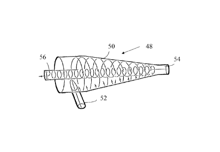
100551 In
another embodiment, a hydrocyclone separator or concentrator is utilized
for delivering alternate pre-mixed proppant slurry and clean fluid. Figure I I
shows an
example of a hydrocYclone separator 48. 'I-he separator includes a generally
conical- or
frusto-conical-shaped body or housing 50 having a tangential fluid inlet 52
where a
proppant slurry is introduced at a high How rate. The flow of fluid through
the tangential
inlet 52 causes the proppant particles to be thrown through centrifugal force
to the
sidewalls of the housing interior where they spiral downward to an underflow
outlet 54.
which may be provided with a control valve (not shown) for controlling the
flow out of
the outlet 54. Lighter fluids and materials move toward the center of the
separator where
they are directed upwards through a central overflow outlet 56. which may be
provided
with a control valve (not shown) for controlling the now out or the outlet 56.
100561 The
hydrocyclone separator allows a concentrated proppant slurry to he
formed from a diluted proppant slurry. In this way, higher concentrations of
proppant in
fluid slugs can be formed than through conventional mixers or blenders and
pumping
equipment. The
concentration of proppant is controlled by the inlet slurry proppant
concentration, which may be a diluted proppant slurry, and the amount of fluid
or
material discharged through the underflow outlet 54 and/or overflow outlet 56.
Thus, for
example, fully closing the outlet 56 so that no fluid is allowed out, a dilute
proppant
slurry may be provided and delivered to the underflow outlet 54. This diluted
proppant
slurry may form the clean fluid with very little proppant concentration (e.g.
2 ppa or 0.24
kg/L or less). By opening the fluid outlet 56 to remove fluid from the slurry,
a
concentrated proppant slurry can be readily formed, which is delivered to the
underllow
outlet 54. Completely opening the outlet vill
allow both fluid and proppant to exit
CA 02799551 2012-11-14
WO 2011/145965 PCT/RU2010/000246
"70
through the underflow outlet. Chokes are required to hold enough back pressure
to allow
fluid to return while the concentrated slurry exits through the overflow
outlet. The
proppant concentration can be significantly and immediately increased or
decreased by
the amount of fluid removed through the outlet. By alternately opening and
closing the
overflow outlet 56, alternating clean fluid and proppant slurry slugs can be
formed for
delivery to the wellbore. Alternatively, clean and proppant slurry may be
delivered
through the overflow outlet 56 by adjUSting through the flow through underflow
outlet
54. Thus, the clean and/or proppant slurries may be provided from either
outlets 54, 56
of the separator 48. Removed streams that are not introduced into the
formation may also
he recycled. The hYdrocyclone provides a quick and efficient method for
providing such
alternating clean and proppant slurry slugs.
Additionally, good control of the proppant
concentration. which can be almost instantaneous, can be achieved through the
use of the
hydrocyclone. In other embodiments. the hYdrocylone 48 may be used solely for
forming
high concentration pre-mixed proppant slurries, as in the embodiments
previously
discussed. with the clean fluid being supplied from a separate source.
100571 In
still another embodiment, the alternating proppant and clean fluid slugs
may be formed from a piston pump that periodically injects a pre-mixed
proppant slurry
into a clean fluid. The pump (not shown) may be a multi-plunger or piston
pump. such as
a tri-plex plunger or piston pump (3 pistons), wherein one of two or more
pistons or
cylinders is used to pump or inject the pre-mixed proppant slurry into the
clean fluid.
100581 With
each of the embodiments described herein. it should be noted that
various equipment and devices not specifically discussed may be employed with
each of
the systems. Such equipment may include flowmeters, densitometers, pressure
gauges,
etc. Additionally, those systems utilizing pre-mixed proppant slurries may
employ re-
circulating lines and pumps for recirculating the pre-mixed proppant slurry to
facilitate
suspension of the proppant. Recirculation of the clean slurry could also be
used. The
recirculation may be provided on the low pressure sick of the system.
100591 With
respect to the methods described herein wherein alternating clean and
proppant fluid slugs are used, it should be noted that non-proppant fibers and
particulate
materials may also be incorporated in each of the clean and/or proppant-
containing
CA 02799551 2016-10-03
54138-209
21
Such materials may be used to facilitate suspension of the proppant to prevent
proppant
settling and to reduce the amount of viscosifyine agent required. Examples of
this are
described in U.S. Patent Application Publication No. US2008/0135242,.
In the heterogeneous proppant placement, the non-proppant particulate
material used to stabilize and suspend the proppant and/or
provide the liquid-liquid interface may be contained in one or both such
adjacent
interfacing fluids. The particulate material may be admixed continuously with
the
fracturing fluids, while the proppant may be added in pulses. In some
embodiments, the
proppant-free fluids or pulses may have a higher content of the non-proppant
particulate
material. In other embodiments, the proppant-laden fluids or pulses may have a
higher
content of non-proppant particulate material. In still other embodiments, the
amount of
non-proppant particulate material may be eenerallv the same in both the
proppant-free
and proppant-laden fluids and be 2enerally continuously dispersed throughout
the fluids.
100601 The systems and methods described herein for alternating_
proppant and clean
fluid slug deliver), may also be used in conjunction with particular
perforation strategies.
Such perforation strategies may include the formation of spaced apart
perforation
clusters. Examples of such perforation strategies are described in
International
Publication Nos. W02009/005387 and W02009/096805.
[00611 While the invention has been shown in only some of its forms, it
should be
apparent to those skilled in the art that it is not so limited, but is
susceptible to various
changes and modifications without departing_ from the scope of the invention.
Accordingly, it is appropriate that the appended claims be construed broadly
and in a
manner consistent with the scope or the invention.