Note: Descriptions are shown in the official language in which they were submitted.
CA 02799594 2012-11-15
WO 2011/144252 PCT/EP2010/057060
A HIGH VOLTAGE DIRECT CURRENT CABLE TERMINATION APPARATUS
Technical Field
The present invention relates to a direct current cable termination appara-
tus for terminating a high voltage direct current, HVDC, cable. The apparatus
comprises a current-carrying device comprising a terminal portion of the
direct cur-
rent cable, the cable at least comprising an electrical conductor, a
circumferential
electrically insulating layer located outside of the electrical conductor, and
a
circumferential conductive shield located outside of the insulating layer and
the
electrical conductor. The apparatus comprises a housing comprising a tubular
io outer shell with an inner periphery, the outer shell defining a
longitudinal axis and
being formed by an electrically insulating and polymer-containing material,
and the
current-carrying device is adapted to extend in the axial direction of the
outer shell.
Along at least a part of the axial extension of the current-carrying device
the outer
shell extends axially with a space between its inner periphery and the current-
car-
is rying device, and the housing is adapted to separate the space from an
atmos-
phere outside the outer shell, and the space is filled with an electrically
insulating
fluid. The outer shell has a first end portion and a second end portion, and
the ap-
paratus comprises at least one electric field control member located at a
first axial
range from the first end portion of the outer shell and at a second axial
range from
20 the second end portion of the outer shell. Further, the present
invention relates to
an electric installation comprising an apparatus of the above-mentioned kind.
Background of the Invention
Today, the level of the rated voltage of high voltage direct current, HVDC,
applications is increased in the technical field of HVDC. With this
development,
25 improved HVDC cable terminations, which can withstand higher voltage
levels, are
required.
A HVDC cable is used for power supply in power distribution networks and
power transmission networks. Generally, the HVDC cable comprises at least an
inner or central live electrical conductor, e.g. made of copper or aluminium,
an
30 electrically insulating layer which circumferentially surrounds the
electrical con-
ductor, and a conductive shield, also called outer semicon, which
circumferentially
surrounds the insulating layer and the electrical conductor, the conductive
shield
being held on ground potential. Additional layers may be provided, e.g. a so
called
CA 02799594 2015-03-23
2
inner semicon, which is a conductive layer circumferentially surrounding the
elec-
trical conductor and located inside of the insulating layer, and an outer
cable jacket
circumferentially surrounding the conductive shield.
When the HVDC cable is electrically connected to other electric equip-
s ment, the HVDC cable is terminated or cut off. When terminating a HVDC
cable,
measures should be taken to ensure durable and reliable electrical performance
and to protect the connection between the end of the HVDC cable and the
electric
equipment to which the end of cable is connected. When terminating a HVDC ca-
ble, the conductive shield and the electrically insulating layer, and possibly
any fur-
l() ther present layers, are terminated, or cut off, prior to the
termination of the inner
electrical conductor in order to expose the electrical conductor and connect
it to
the electric equipment.
W02007/147755-A1 discloses a cable termination for terminating a HVDC
cable, the termination being provided with a device for electric field control
includ-
15 ing a field grading material layer adapted to be electrically connected
to a live high
voltage part and electrically connected to ground potential.
US2009/0071684-A1 describes a high voltage power cable termination.
W02006/015735-A1 discloses an open-air cable sealing end for a high-.
voltage cable, comprising an outer shell and an electrically conducting
connecting
20 line, the outer shell extending axially with a space between its inner
periphery and
the connecting line, and the space is filled with an electrically insulating
gas, e.g.
sulphur hexafluoride, SF6.
Summary of the Invention
An object of the present invention is to provide an improved high voltage
25 direct current, HVDC, cable termination, which may withstand high voltage
levels.
It is a further object of the present invention to improve the electric
insulation prop-
erties of a HVDC cable termination. It is also an object of the present
invention to
improve the mechanical performances of a HVDC cable termination.
30 The above-mentioned objects of the present invention are attained by pro-
viding a direct current cable termination apparatus for terminating a high
voltage
direct current cable (a DC cable for voltages at e.g. 50 kV and above), the
appa-
ratus comprises
CA 02799594 2015-03-23
3
a current-carrying device comprising a terminal portion of the direct current
cable, the cable at least comprising an electrical conductor, a
circumferential elec-
trically insulating layer located outside of the electrical conductor, and a
circumfer-
ential conductive shield located outside of the insulating layer and the
electrical
conductor,
a housing comprising a tubular outer shell with an inner periphery, the
outer shell defining a longitudinal axis and being formed by an electrically
insulat-
ing and polymer-containing material,
the current-carrying device being adapted to extend in the axial direction
io of the outer shell,
along at least a part of the axial extension of the current-carrying device
the outer shell extends axially with a space between its inner periphery and
the
current-carrying device,
the housing is adapted to separate the space from an atmosphere outside
the outer shell, and the space is filled with an electrically insulating
fluid,
the outer shell has a first end portion and a second end portion, the appa-
ratus comprises at least one electric field control member located at a first
axial
range from the first end portion of the outer shell and at a second axial
range from
the second end portion of the outer shell, wherein
the conductive shield terminates inside the outer shell,
the electric field control member is provided inside the outer shell and in
the proximity of the termination of the conductive shield,
a first part of the terminal portion of the cable has the circumferential con-
ductive shield, whereas a remainder part of the terminal portion of the cable
has
the conductive shield removed, the first and remainder parts being located
inside
the outer shell and the first part being situated outside the first axial
range, and
the apparatus comprises at least one field grading material layer posi-
tioned around the current-carrying device, the at least one field grading
material
layer extending axially inside the outer shell and being electrically
connected to the
conductive shield of the terminal portion of the cable and electrically
connectable
to the electrical conductor of the terminal portion of the cable.
CA 02799594 2015-03-23
38
In some embodiments of the present invention, there is provided a direct
current cable termination apparatus for terminating a high voltage direct
current
cable, the apparatus comprising:
a current-carrying device comprising a terminal portion of the direct current
cable, the cable at least comprising an electrical conductor, a
circumferential
electrically insulating layer located outside of the electrical conductor, and
a
circumferential conductive shield located outside of the insulating layer and
the
electrical conductor; and
a housing comprising a tubular outer shell with an inner periphery, the outer
shell defining a longitudinal axis and being formed by an electrically
insulating and
polymer-containing material,
wherein the current-carrying device is adapted to extend in an axial direction
of the outer shell,
wherein along at least a part of the axial extension of the current-carrying
device the outer shell extends axially with a space between an inner periphery
of
the outer shell and the current-carrying device,
wherein the housing is adapted to separate the space from an atmosphere
outside the outer shell, and the space is filled with an electrically
insulating fluid,
wherein the outer shell has a first end portion and a second end portion,
wherein the apparatus further comprises at least one electric field control
member located at a first axial range from the first end portion of the outer
shell and
at a second axial range from the second end portion of the outer shell,
wherein the conductive shield terminates inside the outer shell,
wherein the at least one electric field control member is provided inside the
outer shell and in a proximity of termination of the conductive shield,
wherein a first part of the terminal portion of the cable has the
circumferential
conductive shield, whereas a remainder part of the terminal portion of the
cable has
the conductive shield removed, the first and remainder parts of the terminal
portion
being located inside the outer shell, and the first part of the terminal
portion being
situated outside the first axial range, and
wherein the apparatus comprises at least one field grading material layer
which comprises a non-linear resistive material and which is positioned around
the
current-carrying device, the at least one field grading material layer
extending
axially inside the outer shell and extending at least along the first axial
range, and
CA 02799594 2015-03-23
3b
the at least one field grading material layer is electrically connected,
indirectly or
directly, to the conductive shield of the terminal portion of the cable and
electrically
connected, indirectly or directly, to the electrical conductor of the terminal
portion of
the cable.
Generally, the first end portion may be adjacent to the high voltage side,
e.g.
an overhead line, or the electric equipment to which the cable is to be
connected,
and the cable enters the termination apparatus via the second end portion.
CA 02799594 2012-11-15
WO 2011/144252 PCT/EP2010/057060
4
The at least one field grading material layer may comprise one or more
layers, which is/are directly, or indirectly, electrically connected, or
connectable, to
the conductive shield and the electrical conductor, respectively. The at least
one
field grading material layer may be directly, or indirectly, physically
connected, or
connectable, to the conductive shield and the electrical conductor,
respectively.
A field grading material is a material adapted to grade or to guide the elec-
tric field. Examples of so called field grading material, FGM, which can be
used for
the present invention are for example mentioned in WO-A1-2008/076058 and EP-
A1-1 736 998. However, other suitable FGM may also be used.
The circumferential conductive shield, also called outer semicon or screen,
terminates inside the outer shell and forms a termination in the form of a
circum-
ferential edge (also called semicon edge). The inventors of the present
invention
have identified the termination of the circumferential conductive shield, also
called
outer semicon, which generally is held on ground potential, as a main problem
is zone, where the highest electric field and electric field stress is
found. This is also
the reason for providing an electric field control member, e.g. a so called
stress
cone, in the proximity of the termination of the conductive shield, which is a
prior
art measure. By providing the at least one FGM layer, an efficient control of
the
electric field and a reduction of the electric field stress may be attained,
and the
cable termination according to the present invention is more flexible and may
be
tailored in an efficient way to various applications. By providing the at
least one
FGM layer, the electric stress under impulse test voltages is geometrically
graded
in an efficient way. With reference to the above, an improved cable
termination for
high voltage is provided, which withstands higher voltage levels, and where
the
electric insulation properties and the mechanical performances are improved.
The insulating fluid may be in the form of a liquid, e.g. oil or gel, a gas,
or a
gas mixture etc.
The electrically insulating and polymer-containing material of the outer
shell may comprise one polymer or a plurality of polymers. The material may be
a
composite, a reinforced epoxy or a resin. The polymer can be a thermoplastic
polymer, e.g. polybutylene terephthalate (PBT) or polyester, or a
thermosetting
polymer, e.g. thermosetting resin. The shell may be in the form of an epoxy
reinforced structure. According to an advantageous embodiment of the apparatus
according to the present invention, the outer shell is formed by a polymer or
a plu-
CA 02799594 2012-11-15
WO 2011/144252 PCT/EP2010/057060
rality of polymers. The outer shell may be provided with an outer cover of
silicone,
e.g. in the form of sheds, or wings.
Advantageously, the electric field control member is positioned around the
current-carrying device. There are several known electric field control
members
5 which may be used and are known to the person skilled in the art, and the
electric
field control member is therefore not discussed in more detail hereinafter.
The
electric field control member may for example be a stress cone, and may for ex-
ample comprise a rubber or elastomeric body stretched over the current-
carrying
device, and an earth electrode may be applied to the rubber body to distribute
the
io electric field, or the equipotential lines between the high voltage side
and earth, to
prevent electric field stress and electric field concentrations.
The DC cable may comprise further layers, e.g. an outer cable jacket
circumferentially surrounding the conductive shield, which is known to the
skilled
person and thus not discussed in more detail hereinafter.
According to an advantageous embodiment of the apparatus according to
the present invention, the current-carrying device comprising a terminal
portion of
a High Voltage Direct Current, HVDC, cable. Generally, the conductive shield
is
held on ground potential.
The apparatus according to the present invention is especially advanta-
geous for terminating DC cables for voltages above 200 kV.
According to an advantageous embodiment of the apparatus according to
the present invention, the at least one field grading material layer is
positioned
around and outside of the electrically insulating layer of the terminal
portion of the
cable. Hereby, an improved cable termination for high voltage is provided.
According to a further advantageous embodiment of the apparatus accord-
ing to the present invention, the at least one field grading material extends
at least
along the first axial range. Hereby, an improved cable termination for high
voltage
is provided.
According to another advantageous embodiment of the apparatus accord-
ing to the present invention, the fluid comprises an electrically insulating
gas. The
insulating gas may be a gas mixture. Insulating gas, e.g. SF6, N2 or CO2, is
easy to
handle on site, has a low weight and has an advantageous convection cooling
effect. By this embodiment, an improved HVDC cable termination is provided.
CA 02799594 2012-11-15
WO 2011/144252 PCT/EP2010/057060
6
According to yet another advantageous embodiment of the apparatus ac-
cording to the present invention, the electrically insulating gas comprises
SF6, i.e.
sulphur hexafluoride, CO2 and/or N2. By this embodiment, the insulation
properties
and the electric field control of the HVDC cable termination are further
improved,
providing a further improved HVDC cable termination. The electrically
insulating
gas may also comprise air, e.g. compressed air.
According to still another advantageous embodiment of the apparatus ac-
cording to the present invention, the electric field control member is
situated be-
tween the terminal portion of the cable and the at least one field grading
material
io layer. By this embodiment, the electric field control is further
improved, whereby a
further improved HVDC cable termination is provided.
According to an advantageous embodiment of the apparatus according to
the present invention, the electric field control member has an outer surface
facing
the space of the outer shell, and at least a portion of the outer surface of
the elec-
is tric field control member forms part of the at least one field grading
material layer.
By this embodiment, the electric field control is further improved, whereby a
further
improved HVDC cable termination is provided.
According to a further advantageous embodiment of the apparatus accord-
ing to the present invention, the apparatus comprises a conducting or semicon-
20 ducting layer which electrically connects the at least one field grading
material
layer to the conductive shield of the terminal portion of the cable. By this
embodi-
ment, the electric field control is further improved, whereby a further
improved
HVDC cable termination is provided. Alternatively, the conducting or semicon-
ducting layer may be embedded in the material of the electric field control
mem-
25 ber.
According to another advantageous embodiment of the apparatus accord-
ing to the present invention, the electric field control member is provided
with at
least a part of the conducting or semiconducting layer. By this embodiment,
the
electric field control is further improved, whereby a further improved HVDC
cable
30 termination is provided.
According to still another advantageous embodiment of the apparatus ac-
cording to the present invention, a first part of the outer surface of the
electric field
control member forms part of the at least one field grading material layer,
and a
remainder part of the outer surface of the electric field control member forms
at
CA 02799594 2012-11-15
WO 2011/144252 PCT/EP2010/057060
7
least a part of the conducting or semiconducting layer. By this embodiment,
the
electric field control is further improved, whereby a further improved HVDC
cable
termination is provided.
According to yet another advantageous embodiment of the apparatus ac-
s cording to the present invention, within the first axial range the
current-carrying
device has a first outer surface which extends from the electric field control
mem-
ber to the first end portion of the outer shell, and at least a portion of the
first outer
surface of the current-carrying device forms part of the at least one field
grading
material layer. By this embodiment, the electric field control is further
improved,
io whereby a further improved HVDC cable termination is provided.
According to an advantageous embodiment of the apparatus according to
the present invention, substantially the entire first outer surface of the
current-car-
rying device forms part of the at least one field grading material layer. By
this em-
bodiment, the electric field control is further improved.
15 According to a further advantageous embodiment of the apparatus accord-
ing to the present invention, the remainder part of the terminal portion of
the cable
extends from the termination of the conductive shield to the first end portion
of the
outer shell. By this embodiment, the electric field control is further
improved.
According to another advantageous embodiment of the apparatus accord-
20 ing to the present invention, the electrical conductor of the terminal
portion of the
cable is terminated outside of the outer shell. By this embodiment, the
electric field
control is further improved.
Alternatively, the current-carrying device may comprise a connecting body
positioned within the outer shell and in which the electrical conductor
terminates,
25 the connecting body may be adapted to electrically connect the
terminated electri-
cal conductor to an electrically conducting member adapted to extend axially
in the
first range and to form part of the current-carrying device. The connecting
body
may comprise connecting elements which connect the terminated electrical con-
ductor to the conducting member and may comprise screws and a static conduc-
30 tive screen/shield. The conducting member may be in the form of a rod,
e.g. made
of aluminium or copper. Having a bare conducting member in the space of the
outer shell, which is gas-filled, e.g. with SF6, is of benefit to the thermal
perform-
ance of the DC cable termination.
CA 02799594 2012-11-15
WO 2011/144252 PCT/EP2010/057060
8
According to yet another advantageous embodiment of the apparatus ac-
cording to the present invention, the electrically insulating layer of the
terminal por-
tion of the cable is terminated outside of the outer shell. By this
embodiment, the
electric field control is further improved.
According to still another advantageous embodiment of the apparatus ac-
cording to the present invention, the at least one field grading material
layer com-
prises a nonlinear field grading material. Advantageously, the at least one
field
grading material layer comprises a resistive field grading material. Advanta-
geously, the at least one field grading material layer comprises a nonlinear
resis-
io tive field grading material with a resistivity which is a function of
the electric field.
Alternatively, a capacitive field grading material with field dependent
permittivity
may be used. By these embodiments, the electric field control is further
improved,
and a further improved HVDC cable termination is provided.
According to an advantageous embodiment of the apparatus according to
is the present invention, the apparatus comprises a partition which
separates the
space into a first chamber and a second chamber and separates the second
chamber from the electrically insulating fluid which fills the first chamber,
where
the partition is physically connected to the electric field control member and
is
adapted to separate the first part of the terminal portion of the cable from
the first
20 chamber. The second chamber may be filled with a second fluid different
from the
fluid of the first chamber, e.g. a liquid fluid, e.g. comprising an
electrically insulat-
ing gel and/or oil. When entering the outer shell of the apparatus, the
terminal por-
tion of the DC cable still has the earthed circumferential conductive shield.
Thus,
during operation, the terminal portion of the DC cable thermally expands and
con-
25 tracts in the radial direction at the interface between cable and the
cable en-
try/opening of the outer shell, which may cause problems with regard to the
seal-
ing between the cable and the outer shell. However, by providing a liquid
fluid in
the second chamber into which the cable enters the outer shell, instead of a
gas,
which would more easily leak via the interface between the cable and the outer
30 shell, an improved sealing at the cable entry of the outer shell is
provided. Conse-
quently, the sealing arrangement at the cable entry of the outer shell may be
less
sophisticated and thus less expensive in relation to prior art sealing. Thus,
the ap-
paratus according to this embodiment is easier to manufacture. By this embodi-
ment, an improved HVDC cable termination is provided, where the electric
insula-
CA 02799594 2012-11-15
WO 2011/144252 PCT/EP2010/057060
9
tion properties and the mechanical performances are improved. Further, the
liquid
filler provides cooling of the terminal portion of the DC cable.
According to a further advantageous embodiment of the apparatus accord-
ing to the present invention, the partition is tubular and is positioned
around the
terminal portion of the cable. By this embodiment, the partition is
efficiently seated
in a correct and effective position, and the assembly of the apparatus is
facilitated,
whereby an improved HVDC cable termination is provided.
According to another advantageous embodiment of the apparatus accord-
ing to the present invention, the partition forms a cylinder-shaped inner
shell hav-
m ing a first rim physically connected to the electric field control
member. By this em-
bodiment, the partition is efficiently seated in a correct and effective
position,
whereby an improved HVDC cable termination is provided.
According to yet another advantageous embodiment of the apparatus ac-
cording to the present invention, along at least a part of the axial extension
of the
is partition the outer shell extends axially with a gap between its inner
periphery and
the partition. By this embodiment, the electric field control is further
improved.
According to still another advantageous embodiment of the apparatus ac-
cording to the present invention, the partition has an inner periphery, and
along at
least a part of the axial extension of the current-carrying device the
partition ex-
20 tends axially with a gap between its inner periphery and the current-
carrying de-
vice. By this embodiment, the electric field control is further improved.
According to an advantageous embodiment of the apparatus according to
the present invention, the partition has a periphery which is electrically
conductive.
By this embodiment, the electric field control is further improved.
25 According to an advantageous embodiment of the apparatus according to
the present invention, the at least one field grading material layer has a
varying
thickness along the axial extension of the current-carrying device. By this em-
bodiment, one may take into account of the change in the electric field along
the
axial extension of the current-carrying device, and the at least one field
grading
30 material layer may be efficiently tailored to different HVDC
applications, providing
a further improved electric field control.
According to a further advantageous embodiment of the apparatus accord-
ing to the present invention, the at least one field grading material layer is
based
CA 02799594 2013-11-14
on a tape. Hereby, the assembly of the apparatus is further facilitated,
providing an
improved HVDC cable termination_
According to another advantageous embodiment of the apparatus accord-
ing to the present invention, the at least one field grading material layer is
based
5 on a sleeve. Hereby, the assembly of the apparatus is further
facilitated, providing
an improved HVDC cable termination. Alternatively, the at least one field
grading
material layer may be in the form of a coating or a painted layer applied to
the cur-
rent-carrying device.
According to yet another advantageous embodiment of the apparatus ac-
io cording to the present invention, the electric field control member has
an inner pe-
riphery facing the current-carrying device, and the electric field control
member is
positioned around the current-carrying device with the at least one field
grading
material layer between its inner periphery and the current-carrying device. By
this
embodiment, the application of the at least one field grading material layer
may be
efficiently tailored to each HVDC application, providing a further improved
electric
field control. This embodiment is advantageously combined with the embodiment
which has at least a portion of the outer surface of the electric field
control member
forming part of the at least one field grading material layer.
Advantageously, along at least a part of the first part of the terminal por-
tion of the cable the at least one field grading material layer may extend
axially
and may be positioned around at least the circumferential conductive shield of
the
terminal portion of the cable.
Further, the above-mentioned objects of the present invention are attained
by providing an electric installation, comprising a high voltage direct
current cable
which at least comprises an electrical conductor, a circumferential insulating
layer
located outside of the electrical conductor, and a circumferential conductive
shield
located outside of the insulating layer and the electrical conductor, and
comprising
a direct current cable termination apparatus for terminating the cable,
wherein the
apparatus comprises the features described herein. Positive technical effects
of the
electric installation according to the present invention, and its embodiments,
correspond to the above-mentioned technical effects mentioned in connection
with
the apparatus according to the present invention, and its embodiments.
CA 02799594 2012-11-15
WO 2011/144252 PCT/EP2010/057060
11
The above-mentioned embodiments and features of the direct current ca-
ble termination apparatus and the electric installation, respectively, may be
com-
bined in various possible ways providing further advantageous embodiments.
Further advantageous embodiments of the direct current cable termination
apparatus and the electric installation, respectively, according to the
present in-
vention and further advantages with the present invention emerge from the de-
tailed description of embodiments.
Brief Description of the Drawings
The present invention will now be described, for exemplary purposes, in
io more detail by way of embodiments and with reference to the enclosed
drawings,
in which:
Fig. 1 is a schematic side view showing a longitudinal section of a first
embodiment of the direct current cable termination apparatus ac-
cording to the present invention; and
Fig. 2 is a schematic side view showing a longitudinal section of a sec-
ond embodiment of the direct current cable termination apparatus
according to the present invention.
Detailed Description of Preferred Embodiments
Figs. 1 and 2 schematically shows two embodiments of the direct current
cable termination apparatus according to the present invention, for
terminating a
HVDC cable for high voltage (e.g. 10 kV and above, especially 50 kV and
above).
With reference to Figs. 1 and 2, each of the embodiments of the apparatus com-
prises a current-carrying device 102, or a voltage-carrying device, comprising
a
terminal portion 104 of the HVDC cable, the cable at least comprising a
central live
electrical conductor 106, generally made of a suitable metal, e.g. copper or
alu-
minium, a circumferential electrically insulating layer 108 which
circumferentially
surrounds and is located outside of the electrical conductor 106, and a
circumfer-
ential conductive shield 110, or layer/screen, also called outer semicon,
which
circumferentially surrounds and is located outside of the insulating layer 108
and
the electrical conductor 106. The circumferential conductive shield 110 may be
made of an electrically conducting polymer. The structure of a HVDC cable and
its
parts, which may comprise further layers, is well known to the skilled person
and
thus not discussed in more detail herein. The HVDC cable may e.g. comprise a
so
CA 02799594 2012-11-15
WO 2011/144252 PCT/EP2010/057060
12
called inner semicon, which is a layer/screen circumferentially surrounding
the
electrical conductor and being located inside of the insulating layer. The
inner
semicon may be made of an electrically conducting polymer.
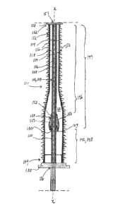
Further, the apparatus comprises a housing 111 which comprises a tubu-
s lar outer shell 112 with an inner periphery 114. The outer shell 112
defines a longi-
tudinal axis x-x and is formed by an electrically insulating and polymer-
containing
material, e.g. a composite. The apparatus is substantially rotation symmetric
around the axis x-x. The outer periphery of the outer shell 112 is provided
with
sheds 116, or lips/wings, for example made of silicone. The current-carrying
de-
vice 102 is adapted to extend in the axial direction of the outer shell 112.
Along at
least a part of the axial extension of the current-carrying device 102 the
outer shell
112 extends axially with a space 118 between its inner periphery 114 and the
outer periphery of current-carrying device 102. The housing 111 is adapted to
separate the space 118 from an atmosphere outside 120 the outer shell 112. The
is conductive shield 110 terminates inside the outer shell 112. The
conductive shield
110 is terminated and forms a termination 109 in the form of a circumferential
edge (also called semicon edge). The apparatus includes an electric field
control
member 128, e.g. in the form of a stress cone as previously disclosed, located
in-
side the outer shell 112 and in the proximity of the termination of the
conductive
shield 110, and is positioned around the current-carrying device 102. The
electric
field control member 128 may comprise a rubber, polymeric or elastomeric body
129 stretched, or pushed, over the current-carrying device 102, more precisely
the
terminal portion 104 of the HVDC cable. The elastomeric body 129 may be mush-
room-shaped. However, other materials and shapes of the elastomeric body 129
are possible. Other types of electric field control members known to the
skilled
person may also be used. The apparatus may also include a plurality of
electric
field control members, i.e. two or several electric field control members. The
elec-
tric field control member could also be in the form of a linear or non-linear
resistive
field grading material layer, e.g. in the form of a sleeve made of a non-
linear resis-
tive material. Further, the electric field control member 128 may comprise a
semi-
conducting, or conductive, layer 130, e.g. made of metal or a polymer
material,
which in conventional ways is provided on the lower inner curved periphery of
the
elastomeric body 129. Alternatively, the semiconducting, or conductive, layer
130
may be embedded in the body 129 of the electric field control member 128. The
CA 02799594 2012-11-15
WO 2011/144252 PCT/EP2010/057060
13
semiconducting, or conductive, layer 130 may be formed and composed in various
ways known to the skilled person. The conductive layer 130 may be called de-
flector. Advantageously, the conductive shield 110 terminates adjacent to the
lower part of the electric field control member 128, below, or prior to, the
triple
s point which is formed by the insulating material of the electric field
control member
128, the insulating material of the electrically insulating layer 108 of the
terminal
portion 104 of the cable and the material of the semiconducting layer 130.
The outer shell 112 has a first end portion 132 adjacent to the high voltage
side, where the apparatus is connected to e.g. an overhead line or bus bar
etc.
io The outer shell 112 has a second end portion 134 via which the HVDC
cable en-
ters the outer shell 112. The housing 111 may comprise a first flange 138,
e.g.
made of a metal, at the second end portion 134 of the outer shell 112, and a
sec-
ond flange 158, e.g. made of a metal, at the first end portion 132 of the
outer shell
112. The cable enters the outer shell 112 via a first opening 136 defined by
the
is first flange 138. The electrically insulating layer 108 and the
electrical conductor
106 of the terminal portion 104 of the cable exit the outer shell 112 via a
second
opening 157 defined by the second flange 158 and are terminated outside 120 of
the outer shell 112, for connection of the electrical conductor 106 to
electric
equipment of the high voltage side. A first part 142 of the terminal portion
104 of
20 the cable has the circumferential conductive shield 110, whereas a
remainder part
144 of the terminal portion 104 of the cable has the conductive shield 110 re-
moved, such that the insulating layer 108 is exposed. The first part 142 may
be
called semicon end and the remainder part 144 may be called stripped cable.
The
first and remainder parts 142, 144 of the terminal portion 104 of the cable
are lo-
25 cated inside the outer shell 112. The remainder part 144 of the terminal
portion
104 of the cable extends from the termination of the conductive shield 110 to
the
first end portion 132 of the outer shell 112. The first part 142, with the
conductive
shield 110 present, is situated between the second end portion 134 and the
elec-
tric field control member 128. The electric field control member 128 is
located at a
30 first axial range 146 from the first end portion 132 of the outer shell
112 and at a
second axial range 148 from the second end portion 134 of the outer shell 112.
The first part 142 of the terminal portion 104 of the cable is situated
outside the
first axial range 146 and within the second axial range 148. Along the axial
exten-
sion of the electric field control member 128 the outer shell 112 extends
axially
CA 02799594 2012-11-15
WO 2011/144252 PCT/EP2010/057060
14
with a space 118 between its inner periphery 114 and the outer periphery of
the
electric field control member 128.
The apparatus comprises at least one circumferential field grading mate-
rial layer, FGM, 150 positioned around the current-carrying device 102, more
pre-
s cisely in this embodiment, around the remainder part 144 of the terminal
portion
104 of the cable, which has the conductive shield 110 removed. The at least
one
FGM layer 150 is electrically connected to the conductive shield 110 of the
termi-
nal portion 104 of the cable by being electrically connected to the
semiconducting
layer 130 which in turn is electrically connected to the conductive shield
110. The
io at least one FGM layer 150 is electrically connectable to the electrical
conductor
106 of the terminal portion 104 of the cable. In the disclosed embodiments,
the
FGM layer 150 may be electrically connected, indirectly or directly, to the
electrical
conductor 106 outside 120 of the outer shell 112 by conventional connection
means.
15 The at least one field grading material layer 150 is herein made of a
nonlinear FGM, e.g. a resistive field grading material with a field dependent
elec-
trical resistivity, e.g. in the form of a SiC or ZnO filler in a suitable
polymer base.
The FGM layer 150 has a varying thickness along the axial extension of the cur-
rent-carrying device 102. Reference is made to WO-A1-2008/076058 and EP-A1 -
20 1 736 998 for examples of FGM which may used. However, other suitable
FGM
may also be used.
The at least one FGM layer 150 extends axially inside the outer shell 112
and extends axially from the semiconducting layer 130 to the first end portion
132
of the outer shell 112. The FGM layer 150 extends axially at least along the
first
25 axial range 146, and is positioned around and outside of the electrical
conductor
106 and the electrically insulating layer 108 of the terminal portion 104 of
the ca-
ble. The electric field control member 128 is situated between the terminal
portion
104 of the cable and the at least one FGM layer 150. The electric field
control
member 128 has an outer surface 152 facing the space 118 of the outer shell
112.
30 A first part of the outer surface 152 of the electric field control
member 128 forms
part of the at least one FGM layer 150, and a remainder part of the outer
surface
152 of the electric field control member 128 forms at least a part of the
semicon-
ducting layer 130. Within the first axial range 146 the current-carrying
device 102
has a first outer surface 154 which extends from the electric field control
member
CA 02799594 2012-11-15
WO 2011/144252 PCT/EP2010/057060
128 to the first end portion 132 of the outer shell 112, and the first outer
surface
154 of the current-carrying device 102 forms part of the at least one FGM
layer
150.
The FGM layer, or FGM layers, may be applied to the apparatus in various
5 ways, e.g. in the form of a tape wound around the current-carrying
device, in the
form of a sleeve positioned around the current-carrying device, or in the form
a
coating or a painted layer applied to the current-carrying device.
The space 118 of the first embodiment of Fig. 1 is filled with an electrically
insulating fluid 125 in the form of an electrically insulating gas, e.g. SF6
or N2, or a
io mixture thereof.
The second embodiment of Fig. 2 comprises a tubular partition 260 which
is positioned around the current-carrying device 102, more precisely around
the
terminal portion 104 of the cable, and separates the space 118 into a first
chamber
262 and a second chamber 264. The partition 260 may be made of an electrically
is insulating and polymer-containing material, for example glass fibre
reinforced ep-
oxy. The first chamber 262 is filled with an electrically insulating first
fluid 266 in
the form of an electrically insulating gas, e.g. SF6 or N2, or a mixture
thereof. The
conductive shield 110 terminates inside the second chamber 264, and the
electric
field control member 128 is located within the second chamber 264. The second
chamber 264 may be filled with an electrically insulating second fluid 268 in
the
form of an electrically insulating gel or an electrically insulating oil, or a
mixture
thereof. Along at least a part of the axial extension of the partition 260 the
outer
shell 112 extends axially with a gap 270 between its inner periphery 114 and
the
outer periphery of the partition 260. The partition 260 is physically
connected to
the electric field control member 128 and is adapted to separate the first
part 142
of the terminal portion 104 of the cable from the first chamber 262. The
partition
260 forms a cylinder-shaped inner shell 260 having a first rim 272 physically
and
sealingly connected to the electric field control member 128. The partition
260 is
connected in a sealing manner to the first flange 138. The partition 260 has
an in-
ner periphery 274, and along at least a part of the axial extension of the
current-
carrying device 102 the partition 260 extends axially with a gap 276 between
its
inner periphery 274 and the current-carrying device 102. The partition 260 has
a
periphery 274, 278 which may be electrically conductive.
CA 02799594 2012-11-15
WO 2011/144252 PCT/EP2010/057060
16
The electric field control member 128 has an inner periphery 159 facing
the current-carrying device 102, and according to further aspects of the
apparatus
according to the present invention, the electric field control member 128 may
also
be positioned around the current-carrying device 102 with at least one FGM
layer
between its inner periphery 159 and the current-carrying device 102. In other
em-
bodiments, further FGM layers may be provided, e.g. both outside of the
electric
field control member 128 and between the inner periphery 159 of the electric
field
control member 128 and the current-carrying device 102.
The invention shall not be considered limited to the embodiments Mus-
ic) trated, but can be modified and altered in many ways by one skilled in
the art,
without departing from the scope the appended claims.