Note: Descriptions are shown in the official language in which they were submitted.
CA 02799617 2012-11-15
WO 2011/159449 PCT/US2011/038106
ROLE-BASED PRESENTATION VIEWS
BACKGROUND
[0001] It is very common in today's business and academic environments for
presentations to be made using a desktop or laptop computer equipped with a
presentation
application program and an external display, such as a projector or a large
monitor.
Meeting participants can view the presentation on the external display.
Remotely located
participants may be able to establish a network connection that enables them
to view the
presentation remotely. Both local and remotely located meeting participants
are typically
provided the same view of the presentation, which is the current focus of the
current
presenter.
[0002] It is also common in today's business and academic environments for
meeting
participants to have one or more computing devices of their own. For instance,
it is not
uncommon for a meeting participant to have a laptop computer and a smartphone.
Meeting participants frequently use these types of computing devices to
perform tasks that
are unrelated to the presentation, such as reading electronic mail ("e-mail")
messages and
browsing the World Wide Web (the "Web"). Use of these devices in this manner
may be
distracting to the meeting participant, to other meeting participants, and to
the presenter.
[0003] It is with respect to these and other considerations that the
disclosure made
herein is presented.
SUMMARY
[0004] Technologies are described herein for providing a view of a
presentation that is
based upon a role assigned to a meeting participant. Through the utilization
of these
technologies, a view of a presentation can be provided to each meeting
participant on their
own computing device that is customized to the particular role and device of
the meeting
participant. By interacting with a view of a presentation that has been
customized for their
particular role and device, meeting participants may become more engaged in
the
presentation and less likely to engage in distractive activities.
[0005] According to one aspect presented herein, a number of client computers
are
configured with a presentation client application. A server computer is also
provided that
is configured with a presentation server application. The presentation server
application is
configured to maintain and synchronize a presentation state among the client
computers.
The presentation state might include a presentation, presentation collateral,
notes,
questions, an attendee list, chat data, annotations, and/or other information.
In other
embodiments, a peer-to-peer network might be utilized to synchronize the
presentation
1
CA 02799617 2012-11-15
WO 2011/159449 PCT/US2011/038106
state between the client computers rather than a server computer. Other
mechanisms
might also be utilized.
[0006] According to another aspect, a client computer executing the
presentation client
application receives a presentation and is assigned a role. The client
computer then
provides a user interface ("UI") for viewing and interacting with the
presentation that is
based upon the assigned role. The role might be a projector role, a presenter
role, an
attendee role, a moderator role, a notetaker role, or another type of role.
The UI might
also be customized for the particular type of client computer that it is
displayed upon. For
instance, the UI might be customized for the particular screen size, available
user input
devices, and other features of the client computer upon which it is presented.
[0007] The projector role is assigned to a client computer that is connected
to an
external display device, such as a projector or large monitor. A client
computer assigned
the projector role is configured to display a presentation on the external
display device.
The portion of the presentation to be displayed by a client computer that has
been assigned
the projector role may be defined by a client computer that has been assigned
a presenter
role. A client computer that has been assigned a presenter role is configured
to display a
UI that includes the presentation. The UI might also include elements to
assist a presenter,
such as presenter notes, a timer, and other UI elements.
[0008] An attendee role might be assigned to client computers operated by non-
presenting meeting participants. Client computers that have been assigned the
attendee
role might present a UI that displays the presentation along with UI elements
to assist a
participant. For instance, the UI might include elements for receiving meeting
notes that
are personal to the participant. The UI might also include elements for
receiving questions
to be directed to the presenter. The questions may then be synchronized to and
displayed
by the client computer that has been assigned the presenter role.
[0009] A moderator role might be assigned to a client computer operated by a
meeting
moderator. The UI presented by a client computer that has been assigned the
moderator
role might display the presentation along with additional UI elements for
assigning roles
for the other client computers participating in the presentation. The roles
assigned by the
moderator may then be synchronized to the other client computers. When a
client
computer receives a new role, it updates its UI to reflect the newly assigned
role. Other
roles, such as the presenter role, might include UI for assigning roles to
other client
computers.
2
CA 02799617 2012-11-15
WO 2011/159449 PCT/US2011/038106
[0010] A notetaker role might be assigned to a client computer operated by an
individual
that has been assigned the task of taking shared notes for the meeting. The UI
provided by
a client computer that has been assigned the notetaker role might display the
presentation
along with additional UI elements for receiving text notes. The text notes may
be
synchronized to the other client computers. For instance, the text notes might
be
synchronized to a client computer that has been assigned the projector role
and thereby
displayed to the meeting participants.
[0011] It should be appreciated that the above-described subject matter may
also be
implemented as a computer-controlled apparatus, a computer process, a
computing
system, or as an article of manufacture such as a computer-readable storage
medium.
These and various other features will be apparent from a reading of the
following Detailed
Description and a review of the associated drawings.
[0012] This Summary is provided to introduce a selection of concepts in a
simplified
form that are further described below in the Detailed Description. This
Summary is not
intended to identify key features or essential features of the claimed subject
matter, nor is
it intended that this Summary be used to limit the scope of the claimed
subject matter.
Furthermore, the claimed subject matter is not limited to implementations that
solve any or
all disadvantages noted in any part of this disclosure.
BRIEF DESCRIPTION OF THE DRAWINGS
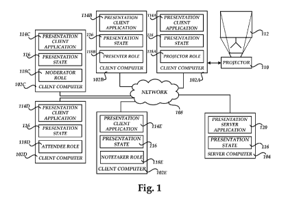
[0013] FIGURE 1 is a network diagram showing aspects of the various software
components provided herein in embodiments;
[0014] FIGURE 2 is a data structure diagram showing aspects of an illustrative
presentation state data structure utilized in embodiments disclosed herein;
[0015] FIGURE 3 is a flow diagram showing aspects of the operation of a
presentation
server application in one embodiment disclosed herein;
[0016] FIGURE 4 is a flow diagram showing aspects of the operation of a
presentation
client application in one embodiment disclosed herein; and
[0017] FIGURE 5 is a computer architecture diagram showing an illustrative
computer
hardware and software architecture for a computing system capable of
implementing the
embodiments presented herein.
DETAILED DESCRIPTION
[0018] The following detailed description is directed to concepts and
technologies for
role-based presentation views. According to aspects presented herein, a
presentation state
that includes a presentation and other information is synchronized between one
or more
3
CA 02799617 2012-11-15
WO 2011/159449 PCT/US2011/038106
client computers executing a presentation client application. A client
computer executing
the presentation client application receives the presentation state, including
the
presentation, and is assigned a role. The client computer then provides a user
interface
("UI") for viewing and interacting with the presentation that is based upon
the assigned
role. The role might be a projector role, a presenter role, an attendee role,
a moderator
role, a notetaker role, or another type of role. The UI might also be
customized for the
particular type of client computer that it is displayed upon. Additional
details regarding
the presentation state, the operation of the client computers, and the various
roles will be
provided below with regard to FIGURES 1-5.
[0019] While the subject matter described herein is presented in the general
context of
program modules that execute in conjunction with the execution of an operating
system
and application programs on a computer system, those skilled in the art will
recognize that
other implementations may be performed in combination with other types of
program
modules. Generally, program modules include routines, programs, components,
data
structures, and other types of structures that perform particular tasks or
implement
particular abstract data types. Moreover, those skilled in the art will
appreciate that the
subject matter described herein may be practiced with other computer system
configurations, including hand-held devices, multiprocessor systems,
microprocessor-
based or programmable consumer electronics, minicomputers, mainframe
computers, and
the like.
[0020] In the following detailed description, references are made to the
accompanying
drawings that form a part hereof, and which are shown by way of illustration
specific
embodiments or examples. Referring now to the drawings, in which like numerals
represent like elements through the several figures, aspects of a computing
system,
methodology, and computer-readable storage medium for role-based presentation
views
will be described.
[0021] Turning now to FIGURE 1, details will be provided regarding one
embodiment
presented herein for role-based presentation views. In particular, FIGURE 1 is
a network
diagram showing aspects of the various software components provided herein in
embodiments. As shown in FIGURE 1, a number of client computers 102A-102E are
utilized in embodiments presented herein. The client computers 102A-102E may
comprise
any type of computer capable of displaying an electronic presentation and a UI
for
interacting with the presentation. For instance, the client computers 102A-
102E may
comprise laptop computers, desktop computers, tablet computers, smartphones,
personal
4
CA 02799617 2012-11-15
WO 2011/159449 PCT/US2011/038106
digital assistants, set top boxes, electronic book readers, and other types of
computing
devices.
[0022] As also shown in FIGURE 1, each of the client computers 102A-102E is
configured to execute a presentation client application 114. The presentation
client
application 114 is an executable software component configured to allow a user
to view
and interact with an electronic presentation. The presentation client
application 114 might
also provide functionality for editing the presentation and for performing
other functions.
[0023] According to one implementation, the presentation client application
114 is the
POWERPOINT presentation client application from MICROSOFT CORPORATION of
Redmond, Washington. It should be appreciated that other presentation client
applications
from other vendors might also be utilized. It should also be appreciated that
while the
embodiments described herein are discussed in the context of a presentation
client
application 114 that performs the functionality described herein, the
functionality
presented herein might be performed by other software components. For
instance, a
standalone software component may be provided for performing the various
functions
described herein. Alternately, a Web page viewable within a Web browser
application
might perform the functionality described herein for providing role-based
presentation
views. Other implementations will be apparent to those skilled in the art.
[0024] As also shown in FIGURE 1, a server computer 104 is utilized in various
embodiments presented herein. The server computer 104 comprises a standard
server
computer and is configured to execute a presentation server application 120.
As will be
disclosed in greater detail herein, the presentation server application 120 is
configured to
communicate with the presentation client applications 114A-114E (which may be
referred
to singularly as the presentation client application 114) executing on the
client computers
102A-102E (which may be referred to singularly as a client computer 102),
respectively.
[0025] The presentation server application 120 is configured to synchronize a
presentation state 116 to each of the client computers 102A-102E. As will be
disclosed in
greater detail below, the presentation state 116 includes a presentation to be
displayed by
the presentation client applications 114A-114E. The presentation state 116
might also
include other data that is synchronized to the client computers 102A-102E and
displayed
by the presentation client applications 114A-114E depending upon a role
assigned to the
particular client computer 102A-102E. Additional detail regarding this process
will be
provided below.
5
CA 02799617 2012-11-15
WO 2011/159449 PCT/US2011/038106
[0026] As illustrated in FIGURE 1, the client computers 102A-102E and the
server
computer 104 are interconnected by way of a network 108. It should be
appreciated that
the network 108 may comprise any suitable computing network for establishing a
communications connection between the client computers 102A-102E and the
server
computer 104. It should also be appreciated that although a single network 108
has been
shown in FIGURE 1, multiple networks might be utilized. For instance, several
of the
client computers 102A-102E may be connected by way of a wireless network.
Other of
the client computers 102A-102E and the server computer 104 might be connected
by way
of a local area network or a wide area network that is connected to the
wireless network.
In this regard, it should be appreciated that one or more of the client
computers 102A-
102E might be located in a common location, such as a meeting room where a
presentation is being given, and other of the client computers 102A-102E and
the server
computer 104 might be remotely located. In this manner, users of the client
computers
102A-102E may view and interact with the presentation in the manner described
herein
whether they are physically located at the site of a presentation or in a
remote location.
[0027] As described briefly above, each of the client computers 102A-102E may
be
assigned a role 118. The role 118 assigned to each of the client computers
102A-102E
may be determined based upon the type of involvement that a user of each of
the client
computers 102A-102E will have in the presentation. The role 118 might also be
assigned
to a particular client computer 102 depending on the role that the client
computer 102 will
have during the presentation. For instance, in the example shown in FIGURE 1,
the client
computer 102A has been assigned a projector role 118A. The projector role 118A
is
assigned to client computer 102A that will provide output of the presentation
to a projector
110 or other type of external display device. In the example shown in FIGURE
1, the
client computer 102A is configured with a projector 110 for displaying on a
display screen
112. Accordingly, the client computer 102A has been assigned the projector
role 118A
which causes the presentation client application 114A to retrieve the
appropriate portion of
the presentation from the presentation state 116 and to cause the presentation
to be
displayed by the projector 110. It should be appreciated that not every role
described
herein will necessarily be assigned to the client computers 102 during each
meeting. All
or a subset of the roles may be assigned to client computers 102.
[0028] As will be described in greater detail below, the presentation state
116 is
synchronized between the various client computers 102A-102E and the server
computer
104. In this way, when a presenter changes the portion of the presentation
that should be
6
CA 02799617 2012-11-15
WO 2011/159449 PCT/US2011/038106
displayed, for instance by selecting a new slide within the presentation, the
presentation
state 116 is updated to reflect the current state of the presentation. When an
updated
presentation state 116 is received, the client computer 102A that has been
assigned the
projector role 108A updates its output to the projector 110 to reflect the
newly selected
slide. In this manner, synchronization of the presentation state 116 allows
the client
computer 102A to continually display the appropriate portion of the
presentation.
[0029] As will also be described in greater detail below, each of the client
computers
102B-102E may also utilize the synchronized presentation state 116 to receive
updates to
the presentation and to add additional information to the presentation state
116 which
might be utilized by other of the client computers 102A-102E or the server
computer 104.
Additional details regarding this process will be provided below with
reference to
FIGURES 2-5.
[0030] In the example shown in FIGURE 1, the client computer 102B has been
assigned
the presenter role 118B. As discussed briefly above, the presenter role 118B
is assigned to
a client computer 102B operated by a user that is the current presenter in a
presentation
meeting. When one of the client computers 102A-102E, such as the client
computer
102B, is assigned the presenter role 118B, the presentation state 116 may be
updated to
include a presentation identified by a user of the client computer 102B.
[0031] When the presentation state 116 is synchronized to the client computer
102A,
which has been assigned the projector role 118A, the presentation identified
by the user of
the client computer 102B would be displayed by the projector 110. In this
manner, the
client computer 102A-102E that has been assigned the presenter role 118B will
determine
the presentation and, more particularly, the portion of the presentation that
should be
displayed by the client computer 102A that has been assigned the projector
role 118A.
[0032] According to one embodiment, the presentation client application 114B
is
configured to generate a UI for viewing and interacting with the presentation
that is based
upon the role 118A assigned to the client computer 102 upon which the
presentation client
application 114 is executing. For instance, because the client computer 102B
has been
assigned the presenter role 118B, the presentation client application 114B may
present a
UI for interacting with the presentation that is customized for use by a
presenter. For
instance, in one embodiment, the presentation client application 114B is
configured to
display a UI for displaying the presentation at the client computer 102B, for
displaying
presenter notes, and for displaying a timer. Other UI elements might also be
displayed by
the presentation client application 114B that are suitable for use by a
presenter.
7
CA 02799617 2012-11-15
WO 2011/159449 PCT/US2011/038106
[0033] In the example shown FIGURE 1, the client computer 102C has been
assigned a
moderator role 118C. The moderator role 118C is assigned to a client computer
102
utilized by an individual that has been assigned the task of moderating a
presentation
meeting. Accordingly, the presentation client application 114C might present a
UI for
viewing and interacting with a presentation that is configured for use by a
moderator. For
instance, in one embodiment, the UI presented by the presentation client
application 114C
includes a user interface for defining the role 118A-118E that is to be
assigned to each of
the client computers 102A-102E. In this manner, a moderator might utilize this
UI to
assign the various roles 118A-118E to the client computers 102A-102E. The user
interface provided by a presentation client application 114C on a client
computer 102C
that has been assigned the moderator role 118C might also include other UI
elements
suitable for use by a moderator of a meeting.
[0034] In the example shown in FIGURE 1, the client computer 102D has been
assigned
an attendee role 118D. The attendee role 118D is assigned to one or more of
the client
computers 102A-102D, such as the client computer 102D, that are utilized by
attendees at
a presentation. Accordingly, the presentation client application 114D is
configured to
display a UI suitable for use by an attendee. In one implementation, the UI
presented by
the client application 114D on a client computer 102D that has been assigned
an attendee
role 118D includes a UI for displaying a presentation and for receiving text
notes from a
user that may or may not be shared with other users.
[0035] The UI presented by the presentation client application 114D might also
include
UI elements for receiving questions from an operator of the client computer
102D. The
questions may be synchronized among the client computers 102A-102D through the
use of
the presentation state 116. Additionally, the questions might be synchronized
to a client
computer 102B that has been assigned the presenter role 118B and displayed to
a user of
the client computer 102B. In this way, attendees of a presentation might
generate
questions for a presenter that are displayed at the client computer 102B
utilized by the
presenter. It should be appreciated that the UI generated by a presentation
client
application 114D executing on a client computer 102D that has been assigned an
attendee
role 118D might include other UI elements not mentioned herein.
[0036] In the example shown in FIGURE 1, the client computer 102E has been
assigned
the notetaker role 118E. The notetaker role 118E is assigned to a client
computer 102E
operated by an individual that has been assigned the task of taking notes
during a
presentation. Accordingly, the presentation client application 114E executing
on a client
8
CA 02799617 2012-11-15
WO 2011/159449 PCT/US2011/038106
computer 102E that has been assigned the notetaker role 118E is configured to
provide a
UI for viewing and interacting with a presentation that is suitable for use by
a note taker.
[0037] In one embodiment, the presentation client application 114E is
configured to
display the presentation to a user of the client computer 102E and to provide
a user
interface for receiving text notes. In order to share the text notes among the
client
computers 102A-102E, the text notes are added to the presentation state 116,
which is then
synchronized between the client computers 102A-102E. The text notes might be
displayed
on the projector 110 by the presentation client application 114A executing on
the client
computer 102A that has been assigned the projector role 118. It should be
appreciated that
the presentation client application 114E executing on a client computer 102E
that has been
assigned a note taker role 118E might also provide other UI elements suitable
for use by
an individual that has been assigned the task of taking notes during a
presentation.
[0038] It should also be appreciated that the roles 118A-118E shown in FIGURE
1 are
merely illustrative and that other roles might be assigned to the various
client computers
102A-102E. It should also be appreciated that, according to embodiments, the
UI
displayed by the presentation client application 114 might also be customized
based upon
the type of client computer 102A-102E upon which the presentation client
application 114
is executing. For instance, the UI might be customized for the particular
screen size,
available user input devices, and other hardware and software features of the
client
computer 102 upon which it is executing. In this manner, the UI presented to
users of the
client computers 102A-102E might be customized based upon the role 118 that
has been
assigned to the respective client computer 102A-102E, and upon the particular
hardware
or software characteristics of the respective client computer 102A-102E. It
should also be
appreciated that, according to embodiments, a client computer 102 or user
might be
assigned two or more roles. For instance, a client computer 102A might be
assigned a
presenter role and a projector and/or moderator role.
[0039] As mentioned briefly above, the presentation state 116 is synchronized
among
the client computers 102A-102E in the various embodiments presented herein. In
one
implementation, the server computer 104 is utilized to synchronize the
presentation state
between the client computers 102A-102E. It should be appreciated, however,
that other
types of mechanisms might be utilized to synchronize the presentation state
116 between
the client computers 102A-102E. For instance, in one embodiment, the server
computer
104 is not utilized. In this embodiment, the client computers 102A-102E are
configured as
a peer-to-peer network. Using the peer-to-peer network, the client computers
102A-102E
9
CA 02799617 2012-11-15
WO 2011/159449 PCT/US2011/038106
can synchronize the presentation state 116 without the use of a dedicated
server computer
104. It should be appreciated that other mechanisms might be utilized to
synchronize the
presentation state 116 between the client computers 102A-102E. Additional
details
regarding the structure and use of the presentation state 116 and the
operation of the
presentation client application 114 will be provided below with respect to
FIGURES 2-5.
[0040] Referring now to FIGURE 2, a data structure diagram will be described
that
shows aspects of an illustrative data structure for implementing the
presentation state 116
in one embodiment presented herein. As discussed briefly above, the
presentation state
116 includes a presentation 202. The presentation 202 might include one or
more slide
decks, each of which includes one or more slides. The presentation 202 might
also include
state data indicating which of the slides should be currently displayed.
[0041] According to one embodiment, the presentation state 116 also includes
presentation collateral 204. Presentation collateral 204 includes any type of
electronic
document that might be associated with and utilized in conjunction with a
presentation
202. For instance, the presentation collateral 204 might include pictures,
audio files, video
files, and other types of media. Presentation collateral 204 might also
include other types
of documents. The presentation collateral 204 might also be stored within the
presentation
202.
[0042] As described briefly above, the presentation state 116 might be
utilized to
synchronize various other types of information between the client computers
102A-102E.
Accordingly, in various embodiments, the presentation state 116 includes notes
206,
questions 208, an attendee list 210, chat data 212, and annotations 214. The
notes 206
might be notes taken by a user of the client computer 102E that has been
assigned the note
taker role 118E. As discussed above, the notes 206 might be synchronized
between the
client computers 102A-102E and displayed by the client computer 102A that has
been
assigned the projector role 118A.
[0043] As also discussed above, the presentation client application 114D
executing on a
client computer 102D that has been assigned the attendee role 118D might
provide a user
interface to allow an attendee to ask a question of the presenter. In the
regard, questions
208 may be included in the presentation state 116 and synchronized to the
client computer
102B operated by the presenter.
[0044] According to implementations, the presentation client application 114E
might
include functionality for allowing users of the client computers 102A-102E to
chat with
one another by typing text messages, exchanging audio, and/or audio/video.
These
CA 02799617 2012-11-15
WO 2011/159449 PCT/US2011/038106
messages, which might be referred to herein as chat data 212, may be included
in the
presentation state 116 and synchronized among the client computers 102A-102E.
[0045] In other embodiments, the presentation client application 114D provides
functionality for allowing an operator of one of the client computers 102A-
102E that has
been assigned an appropriate role 118 to annotate the currently displayed
presentation.
The annotations are textual or graphic information that will be displayed
along with the
presentation by the client computer 102A that has been assigned the projector
role 118.
The annotations 214 are included in the presentation state 116 and
synchronized among
the client computers 102A-102E.
[0046] As shown in FIGURE 2, the presentation state 116 might also include an
attendee list 210. The attendee list 210 might include the names of the
operators of each
of the client computers 102A-102E. The attendee list 210 might also identify
the particular
role 118A-118E that each of the client computers 102A-102E has been assigned.
When a
role is changed for a particular client computer 102A-102E, such as when the
presenter
changes, the attendee list 210 might be updated to reflect the new role.
Additional details
regarding modification of a role 118 on a particular client computer 102B will
be
described below with respect to FIGURE 4.
[0047] Turning now to FIGURE 3, additional details will be provided regarding
the
embodiments presented herein for role-based presentation views. In particular,
FIGURE 3
is a flow diagram showing a routine 300 that illustrates aspects of the
operation of the
presentation server application 120 in one embodiment disclosed herein.
[0048] It should be appreciated that the logical operations described herein
are
implemented (1) as a sequence of computer implemented acts or program modules
running on a computing system and/or (2) as interconnected machine logic
circuits or
circuit modules within the computing system. The implementation is a matter of
choice
dependent on the performance and other requirements of the computing system.
Accordingly, the logical operations described herein are referred to variously
as
operations, structural devices, acts, or modules. These operations, structural
devices, acts
and modules may be implemented in software, in firmware, in special purpose
digital
logic, and any combination thereof. It should also be appreciated that more or
fewer
operations may be performed than shown in the figures and described herein.
These
operations may also be performed in a different order than those described
herein.
[0049] The routine 300 begins at operation 302, where the server computer 104
receives
connection requests from the presentation client applications 114A-114E
executing on the
11
CA 02799617 2012-11-15
WO 2011/159449 PCT/US2011/038106
client computers 102A-102E. The routine 300 then proceeds to operation 304,
where the
presentation server application 120 assigns roles 118A-118E to the connected
client
computers 102A-102E. According to embodiments, the roles 118A-118E may be
automatically assigned to the client computers 102A-102E as they connect to
the server
computer 104. As discussed above, a client computer 102C that has been
assigned the
moderator role 118C might also be used to assign roles 118 to each of the
client computers
102A-102E.
[0050] From operation 304, the routine 300 proceeds to operation 306, where
the server
computer 104 receives the presentation 202 from the client computer currently
assigned
the presenter role 118B. The routine 300 then proceeds to operation 308, where
the server
computer 104 assembles the presentation state 116. This might include adding
the
presentation 202, presentation collateral 204, notes 206, questions 208,
attendee list 210,
chat data 212, and annotations 214 to the presentation state 116.
[0051] From operation 308, the routine 300 proceeds to operation 310, where
the server
computer 104 transmits the presentation state 116 to each of the connected
client
computers 102A-102E. The routine 300 then proceeds to operation 312, where the
server
computer 104 receives changes to the presentation state 116 from the connected
client
computers 312. As discussed above, changes may occur, for instance, when a
presenter
modifies the currently displayed presentation slide, when attendees add
questions, when
attendees join or exit the presentation, or for other reasons.
[0052] From operation 312, the routine 300 proceeds to operation 314, where
the
presentation server application 120 determines whether the presentation state
116 has been
changed. If the presentation state 116 has been changed, the routine 300
proceeds to
operation 316 where the server computer 104 updates that presentation state
116. The
routine 300 then proceeds from operation 316 to operation 310 where the
updated
presentation state 116 is transmitted to the client computers 102A-102E.
[0053] If, at operation 314, the presentation server application 120
determines that the
presentation state 116 has not been changed, the routine 300 proceeds from
operation 314
to operation 318. At operation 318, the server computer 104 determines whether
a request
has been received to terminate the current presentation. If not, the routine
300 proceeds to
operation 312, described above, where additional changes to the presentation
state 116
may be received and synchronized to the client computers 102A-102E. If the
presentation
is to be ended, the routine 300 proceeds from operation 318 to operation 320
where the
client computers 102A-102E are disconnected from the server computer 104.
Operation
12
CA 02799617 2012-11-15
WO 2011/159449 PCT/US2011/038106
of the presentation server application 120 may then terminated. From operation
320, the
routine 300 proceeds to operation 322, where it ends.
[0054] Referring now to FIGURE 4, an illustrative routine 400 will be
described that
illustrates operation performed by the presentation client application 114
executing on the
client computers 102A-102B. In particular, the routine 400 begins at operation
402, where
the presentation client application 114 connects to the server computer 104.
The routine
400 then proceeds to operation 404 where the presentation client application
114 receives
the presentation state 116 from the server computer 104. The presentation
client
application 104 also receives an assignment of a role 118 from the server
computer 104.
As discussed above, the role may be specified in an attendee list 210
contained in the
presentation state 116. The role 118 may also be specified in another manner.
[0055] From operation 406, the routine 400 proceeds to operation 408 where the
presentation client application 114 provides a UI for viewing and interacting
with the
presentation 202 based upon the role 118 assigned to the client computer 102
upon which
the presentation client application 114 is executing. As also discussed above,
the
presentation client application 114 may provide a UI that is customized for
the particular
hardware or software of the client computer 102 upon which it is executing.
[0056] From operation 408, the routine 400 proceeds to operation 410, where
the
presentation client application 104 determines whether changes have been made
to the
presentation state 116. For instance, the presentation client application 114
may determine
that notes 206, questions 208, chat data 212, or annotations 214 have been
added to the
presentation state 116 by a user of the client computer 102 upon which it is
executing. If
so, the routine 400 proceeds to operation 412 where the updated presentation
state 116
may be transmitted to the server computer 104. Alternately, only the changed
data may be
transmitted to the server computer 104 for inclusion in the presentation state
116. If no
changes have been made, the routine 400 proceeds to operation 414.
[0057] At operation 414, the presentation client application 114 determines
whether a
new role has been received from the server computer 104. For instance, a
presentation
state 116 may be received with an updated attendee list 210 that indicates
that the role for
a particular client computer 102 has been changed. If the role has been
changed, the
routine 400 proceeds to operation 416, where the presentation client
application 114
updates the user interface for viewing and interacting with the presentation
202 based
upon the newly assigned role 118. For instance, during a presentation, an
individual at the
presentation may be an attendee for most of the presentation. During this
time, the client
13
CA 02799617 2012-11-15
WO 2011/159449 PCT/US2011/038106
computer 102D which they are operating will be assigned an attendee role 118D.
At some
point during the presentation, the attendee may be asked to become the
presenter. When
this occurs, the client computer 102D utilized by the attendee will be
assigned the
presenter role 118B. When the client computer 102B is assigned presenter role
118B, the
UI provided by the presentation client application 114D will be modified to
reflect the
newly assigned role. In this manner, a user of the client computer 102D will
be provided a
UI suitable for presenting a presentation. It should be appreciated that other
role changes
may be processed in a similar fashion.
[0058] From operation 416, the routine 400 proceeds to operation 418 where a
determination is made as to whether a user has requested to shut down the
presentation
client application 114. If not, the routine 400 proceeds to operation 410,
described above,
where the processing described above continues. If a request is received to
shut down the
presentation client application 114, the presentation client application 114
is disconnected
from the server computer 104 and its execution is terminated. The routine 400
then
proceeds to operation 420, where it ends.
[0059] FIGURE 5 shows an illustrative computer architecture for a computer 500
capable of executing the software components described herein for role-based
presentation
views. The computer architecture shown in FIGURE 5 illustrates a conventional
desktop,
laptop computer, or server computer and may be utilized to execute the
presentation client
application 114 or any of the other software components described herein.
[0060] The computer architecture shown in FIGURE 5 includes a central
processing
unit 502 ("CPU"), a system memory 508, including a random access memory 514
("RAM") and a read-only memory ("ROM") 516, and a system bus 504 that couples
the
memory to the CPU 502. A basic input/output system ("BIOS") containing the
basic
routines that help to transfer information between elements within the
computer 500, such
as during startup, is stored in the ROM 516. The computer 500 further includes
a mass
storage device 510 for storing an operating system 518, application programs,
and other
program modules, which will be described in greater detail below.
[0061] The mass storage device 510 is connected to the CPU 502 through a mass
storage
controller (not shown) connected to the bus 504. The mass storage device 510
and its
associated computer-readable media provide non-volatile storage for the
computer 500.
Although the description of computer-readable media contained herein refers to
a mass
storage device, such as a hard disk or CD-ROM drive, it should be appreciated
by those
14
CA 02799617 2012-11-15
WO 2011/159449 PCT/US2011/038106
skilled in the art that computer-readable storage media can be any available
computer
storage media that can be accessed by the computer 500.
[0062] By way of example, and not limitation, computer-readable storage media
may
include volatile and non-volatile, removable and non-removable media
implemented in
any method or technology for storage of information such as computer-readable
instructions, data structures, program modules or other data. For example,
computer-
readable storage media includes, but is not limited to, RAM, ROM, EPROM,
EEPROM,
flash memory or other solid state memory technology, CD-ROM, digital versatile
disks
("DVD"), HD-DVD, BLU-RAY, or other optical storage, magnetic cassettes,
magnetic
tape, magnetic disk storage or other magnetic storage devices, or any other
medium which
can be used to store the desired information and which can be accessed by the
computer
500. As used herein, the term computer-readable storage media does not
encompass
transitory signals.
[0063] According to various embodiments, the computer 500 may operate in a
networked environment using logical connections to remote computers through a
network
such as the network 520. The computer 500 may connect to the network 520
through a
network interface unit 506 connected to the bus 504. It should be appreciated
that the
network interface unit 506 may also be utilized to connect to other types of
networks and
remote computer systems. The computer 500 may also include an input/output
controller
512 for receiving and processing input from a number of other devices,
including a
keyboard, mouse, or electronic stylus (not shown in FIGURE 5). Similarly, an
input/output controller may provide output to a display screen, a printer, or
other type of
output device (also not shown in FIGURE 5).
[0064] As mentioned briefly above, a number of program modules and data files
may be
stored in the mass storage device 510 and RAM 514 of the computer 500,
including an
operating system 518 suitable for controlling the operation of a networked
desktop, laptop,
or server computer. The mass storage device 510 and RAM 514 may also store one
or
more program modules. In particular, the mass storage device 510 and the RAM
514 may
store the presentation client application 114, the presentation state 116, the
role 118, and
the other program modules and data described above. The mass storage device
510 and
RAM 514 may also store other program modules and data.
[0065] In general, software applications or modules may, when loaded into the
CPU 502
and executed, transform the CPU 502 and the overall computer 500 from a
general-
purpose computing system into a special-purpose computing system customized to
CA 02799617 2012-11-15
WO 2011/159449 PCT/US2011/038106
perform the functionality presented herein. The CPU 502 may be constructed
from any
number of transistors or other discrete circuit elements, which may
individually or
collectively assume any number of states. More specifically, the CPU 502 may
operate as
one or more finite-state machines, in response to executable instructions
contained within
the software or modules. These computer-executable instructions may transform
the CPU
502 by specifying how the CPU 502 transitions between states, thereby
physically
transforming the transistors or other discrete hardware elements constituting
the CPU 502.
[0066] Encoding the software or modules onto a mass storage device may also
transform
the physical structure of the mass storage device or associated computer
readable storage
media. The specific transformation of physical structure may depend on various
factors,
in different implementations of this description. Examples of such factors may
include,
but are not limited to: the technology used to implement the computer readable
storage
media, whether the computer readable storage media are characterized as
primary or
secondary storage, and the like. For example, if the computer readable storage
media is
implemented as semiconductor-based memory, the software or modules may
transform the
physical state of the semiconductor memory, when the software is encoded
therein. For
example, the software may transform the states of transistors, capacitors, or
other discrete
circuit elements constituting the semiconductor memory.
[0067] As another example, the computer readable storage media may be
implemented
using magnetic or optical technology. In such implementations, the software or
modules
may transform the physical state of magnetic or optical media, when the
software is
encoded therein. These transformations may include altering the magnetic
characteristics
of particular locations within given magnetic media. These transformations may
also
include altering the physical features or characteristics of particular
locations within given
optical media, to change the optical characteristics of those locations. Other
transformations of physical media are possible without departing from the
scope and spirit
of the present description, with the foregoing examples provided only to
facilitate this
discussion.
[0068] Based on the foregoing, it should be appreciated that technologies for
role-based
presentation views have been presented herein. Although the subject matter
presented
herein has been described in language specific to computer structural
features,
methodological acts, and computer readable media, it is to be understood that
the
invention defined in the appended claims is not necessarily limited to the
specific features,
16
CA 02799617 2012-11-15
WO 2011/159449 PCT/US2011/038106
acts, or media described herein. Rather, the specific features, acts and
storage mediums
are disclosed as example forms of implementing the claims.
[0069] The subject matter described above is provided by way of illustration
only and
should not be construed as limiting. Various modifications and changes may be
made to
the subject matter described herein without following the example embodiments
and
applications illustrated and described, and without departing from the true
spirit and scope
of the present invention, which is set forth in the following claims.
17