Note: Descriptions are shown in the official language in which they were submitted.
CA 02799644 2012-11-16
WO 2011/144479 PCT/EP2011/057423
1
BEVERAGE PRODUCTION SYSTEM USING CAPSULES
The present invention relates to the field of producing beverages or other
liquid
comestibles on the basis of ingredients which are contained in a capsule.
The capsule is inserted into the beverage production module of a beverage
production
machine. The module is designed to inject a liquid such as for example hot
water into the
capsule in order to have the liquid interacts with the ingredients contained
in the capsule. Note
that some beverage production techniques ask for a pressurized injection like
coffee beverage,
others such as e.g. brewing tea can be made at ambient pressure. The invention
can find
application in both scenarios. The result of the interaction, i.e. the
produced beverage or liquid
comestible, is then drained from the capsule and fed to a receptacle such as
e.g. a cup placed
below an outlet for the beverage.
The invention relates particularly to beverage production machines comprising
a module
with a first capsule engagement member, which can be displaced relative to a
second co-
operating capsule engagement member between an opened capsule insertion
position and a
closed capsule-enclosure position. The module comprises means for actively
retracting the
capsule from the beverage production position to a capsule discharge position
in which the
capsule is discharged from the module. Such a machine presents the advantage
of having a
capsule discharge position which is offset relative to the beverage production
position. This
advantage is of interest when the machine and the capsule are conceived for
delivering the
beverage directly out of the capsule in a cup without the beverage contacting
the machine since
it enables the discharge of the capsule in a position which is offset relative
to the vertical of the
beverage flow path. Such a beverage production machine is described in EP-A1-2
033 551.
In such a machine, the capsule is introduced in the beverage production
module, retains
by pre-fixation arms in a pre-engagement position and then engaged by a first
engagement
member that is conformal to the capsule shape further to the movement of the
first engagement
member to the capsule. At the end of this movement, the capsule is clamped
between the first
and the second engagement members and the diluent, generally water, can be
introduced to
interact with the ingredients in the capsule. The resulting beverage flows out
of the capsule
either through en outlet provided in the capsule or/and produced by the
machine during the
capsule engagement and falls by gravity in a cup. Once the beverage has been
delivered, the
first engagement member moves back to the capsule discharge position dragging
the capsule
towards a position offset relative to the vertical of the beverage flow path.
The movement of the
first engagement member is a combination of a linear movement and an end
swivelling
movement so that the capsule can fall by gravity from the first engagement
member.
CA 02799644 2012-11-16
WO 2011/144479 PCT/EP2011/057423
2
Yet it has been noticed that the end swivelling movement is not systematically
sufficient to
make the capsule drop from the first engagement member to a capsule recovery
container,
particularly if the consumer has not discharged the capsule immediately after
having prepared a
beverage. In this situation it has been noticed that the capsule can stick to
the first engagement
member and that the capsule does not disengage which blocks the machine.
Besides such a machine comprises in its first capsule engagement member a
hollow
needle for opening the capsule and injecting water in the capsule. According
to an embodiment
this needle is retractable and the retraction can help in ejecting the capsule
from the first
engagement member at the capsule discharge position. But according to another
embodiment,
the needle is not retractable and continuously protrudes in the first capsule
engagement
member and in the capsule. This needle may retain the capsule in the first
engagement member
in spite of the swivelling movement and may prevent the discharge of the
capsule from the
beverage production module, which would block the machine.
The invention now targets at a reliable discharge of the capsule from such a
beverage
production machine, particularly the machine described in EP-A1-2 053 551.
This object is achieved by means of specific features of the machine and the
capsules.
This system comprising these both objects guarantees a systematic efficient
discharge of the
capsule from the capsule engagement member.
The invention concerns a beverage production system comprising a capsule and a
module
for producing a beverage from the capsule,
- the capsule comprising an enclosure and a rim, and
- the module comprising :
. a first capsule engagement member, which can be displaced relative to a
second, co-
operating capsule engagement member between a beverage production position and
a
capsule discharge position,
. means for actively retracting the first capsule engagement member from the
beverage
production position to the capsule discharge position in which the capsule is
discharged
from the first capsule engagement member and which is offset relative to the
vertical of
the beverage flow path,
the displaceable first capsule engagement member comprising an element having
the shape of
a hollow bell member and
the capsule presenting an enclosure outer shape that is conformal to at least
a portion of the
CA 02799644 2012-11-16
WO 2011/144479 PCT/EP2011/057423
3
hollow bell member and the capsule presenting a rim size such that at least a
part of the rim of
the capsule extends beyond at least a part of the first capsule engagement
member once
engaged in the first capsule engagement member,
wherein the displaceable first capsule engagement member comprises retaining
means able to
create friction with discrete parts of the outer shape of the enclosure of the
capsule, and
wherein the module comprises means for engaging the rim of the capsule
extending beyond the
first capsule engagement member when the first capsule engagement member is
displaced from
the beverage production position to its capsule discharge position.
The module for producing a beverage of the system can present the features of
the
module described in EP-A1-2 053 551. It comprises two co-operating capsule
engagement
members, the first member being displaceable between a closed position in
which the capsule is
engaged between the two members and called the beverage production position
and an open
position in which no capsule is engaged by the members and called the capsule
discharge
position. According to the invention the capsule discharge position is offset
relative to the
vertical of the beverage flow path that is to the beverage production
position.
The module comprises means for displacing the first capsule engagement member
between the two positions.
Generally the module is designed for injecting water into the capsule and
draining the
beverage from the capsule while the capsule is in the beverage production
position.
The capsule of the system of the present invention comprises an enclosure in
which
beverage ingredients are contained. These ingredients can be for example
selected in the
following list : tea leaves, herbal or fruit tea leaves, roast and ground
coffee, soluble beverage
ingredients, ... The enclosure is usually a cup-shaped housing which can
encompass different
cross sections such as triangular, circular, ellipsoid, egg-shaped, square,
rectangular or
polygonal section. The enclosure is usually closed by a cover, preferably a
plane cover. The
capsule of the present invention also presents a rim at the edge of the
enclosure. The cover can
be fixed on this rim. The capsule is preferably made of a material
sufficiently rigid (either due to
its nature or to its thickness) so that it is not deformed by the friction
means of the first capsule
engagement member when it is engaged in said member. Otherwise the friction
force could not
be sufficiently strong to retain the capsule during the movement of the first
capsule engagement
member.
According to the invention the displaceable first capsule engagement member
comprises
an element having the shape of a hollow bell member and the capsule presents
an enclosure
outer shape that is conformal to at least a portion of said hollow bell
member. By "conformal", it
CA 02799644 2012-11-16
WO 2011/144479 PCT/EP2011/057423
4
is meant that the capsule outer shape is defined in order to match at least a
portion of the hollow
bell shape outer shape. Thus at least a part of the outer contour of the
capsule can be housed in
the hollow bell member.
Besides the capsule presents a rim size such that at least a part of the rim
of the capsule
extends beyond the first capsule engagement member once it is engaged in the
first capsule
engagement member.
According to the invention the displaceable first capsule engagement member
comprises
retaining means able to create a friction with discrete parts of the outer
shape of the enclosure
of the capsule. These retaining means can be friction means that exerts a
friction on the capsule
enclosure outer wall when it is engaged in the first capsule engagement
member.These
retaining means are preferably positioned inside the hollow bell member of the
first engagement
member
According to a preferred embodiment the retaining means that engage discrete
parts of
the periphery of the outer shape of the enclosure of the capsule are discrete
bumps placed on
the internal surface of the hollow bell member of the first capsule engagement
member.
Preferably the bumps are made of a flexible and resilient material. The
material can be
elastomeric, for example a silicone rubber or an EPDM (ethylene propylene
diene monomer)
rubber.
If the capsule section presents a symmetrical shape, the bumps are preferably
placed by
pairs at the internal surface of the hollow bell member and the two bumps of a
pair are
symmetrically opposed in view of the symmetrical plane or axis of the capsule
when it is
engaged in the first capsule engagement member. Then each pair of bumps forms
a sort of pair
of pliers that maintains and retains the capsule in the first capsule
engagement member when
this member moves back to the capsule discharge position.
Even more preferably, if the capsule presents a vertical plan of symmetry in
its extracting
position then the first engagement member can comprise four bumps, the first
pair being
vertically opposed along the plane of symmetry and the second pair being
horizontally opposed
in view of the plan of symmetry.
According to the invention the module comprises also means for engaging the
rim of the
capsule that extends beyond the first capsule engagement member when the first
capsule
engagement member is displaced from the beverage production position to its
capsule
discharge position. This means can simply be a tab extending from the housing
of the beverage
machine supporting the module.
Preferably in the module of the system of the present invention the means for
actively
CA 02799644 2012-11-16
WO 2011/144479 PCT/EP2011/057423
retracting the first capsule engagement member from the beverage production
position to the
capsule discharge position are designed to implement the combination of a
linear movement
and a swivelling end movement.
Usually the first capsule engagement member comprises opening means for
piercing the
5 capsule and injecting water in the capsule. The opening means can be a
hollow needle linked to
water supply.
Preferably the module of the system of the present invention comprises pre-
fixation means
which are provided at a lateral side of the capsule and designed to engage
with the rim of the
capsule for fixation of the capsule close to the second engagement member
before the
beverage production.
The module can comprise means for opening the cover. These means are generally
placed adjacent to the second capsule engagement member or can even be part of
this second
capsule engagement member.
Brief description of the drawings
The characteristics and advantages of the invention will be better understood
in relation to
- Fig. 1 a-1 c show a sequence for illustrating the transfer from a capsule
insertion state, (Fig. 1 a)
to a beverage production position (Fig. 1c) with a beverage machine in which
the system of the
present invention can be implemented,
- Fig. 2a-2e show the complete cycle for transferring a beverage production
module that can be
implemented according to the present invention from a capsule insertion state
(Fig. 2a) to a
capsule production position (Fig. 2c) and to the capsule discharge position
(Fig. 2e).
- Figure 3 illustrates a first capsule engagement member used in the system of
the present
invention.
- Figure 4 illustrates a capsule used in the system of the present invention
with the first capsule
engagement member of Figure 3.
- Figure 5a is a back view of the first capsule engagement member of Figure 3
with the capsule
of Figure 4 engaged inside and Fig.5b is the corresponding front view.
- Figures 6a-6e illustrate the relative positions of first capsule engagement
member, the capsule
and the pre-fixation means during the movement of the first capsule engagement
member
during a cycle of beverage production according to a first embodiment.
- Figures 7a-7c illustrate the relative positions of first capsule engagement
member, the capsule
and the pre-fixation means during the movement of the first capsule engagement
member from
CA 02799644 2012-11-16
WO 2011/144479 PCT/EP2011/057423
6
the beverage production position (fig. 7a) to the capsule discharge position
(fig. 7c) according to
a second embodiment.
- Figure 8 shows an isolated view of the first engagement member and the means
for displacing
said member.
Detailed description of the drawings
Throughout the figures only the beverage production module 2 of a beverage
production
machine is shown. Usually the beverage production module 2 is supplied with a
liquid at a liquid
inlet 14 which can be in fluid connection with means for heating and/or
pressurizing the supplied
liquid. At the outlet side, means for guiding a produced beverage or liquid
comestible to a
designated outlet of the beverage production machine can be provided. The
beverage
production module 2 as shown in the figures is preferably housed in a casing
of the beverage
production machine such that it assumes an essentially horizontal position.
Figure 1a shows a state of the beverage production module 2 in which a capsule
1 being
at least partially filled with ingredients 5 can be inserted from the top
through an opening (slot) 8
of a casing 19 of the beverage production module 2. Figure 1 a shows the state
in which the
capsule 1 has been already manually inserted by a user from the top through
the opening 8 into
the interior of the casing 19 of the beverage module 2. Preferably in the
state as shown in Fig.
1 a the capsule 1 is held by pre-fixation means which will be explained later
on in detail referring
to Fig. 6 and 7. As can be seen in Fig. 1 a, in this pre-fixation position the
capsule 1 is preferably
held in an essentially vertical orientation, i.e. the symmetrical axis of the
capsule is essentially
horizontal. Other pre-positioning arrangements of the capsule 1 can be thought
of in which the
capsule 1 is held in an orientation which forms a small (acute) angle vis-a-
vis the vertical axis. In
the state as shown in Fig. 1a the capsule is pre-fixed close to a second
engagement member 4
which can comprise means for opening (perforating, etc.) the face of the
capsule adjacent to the
second engagement member 4. This second engagement member 4 can also comprise
means
for or guiding a produced beverage or liquid comestible from the capsule 1 to
a cup. The first
engagement member 3 is in an opened state, i.e. as controlled by a manual
actuator
mechanism in the capsule insertion state as shown in Fig. 1a, the first
capsule engaging
member 3 is distanced from the second engagement member 4, wherein this
distance is
substantially larger than the corresponding dimensions of the capsule 1.
According to a
preferred aspect which will be explained in detail later on, optionally the
first engagement
member 3 is not only distanced from, but also slightly rotated vis-a-vis the
main plane formed by
CA 02799644 2012-11-16
WO 2011/144479 PCT/EP2011/057423
7
the second engagement member 4.
In the embodiment of Fig. 1 the first engagement member 3 is provided with
capsule
opening means, which can be perforation means such as a hollow needle 6. In
Fig. 1a the
perforation means 6 are in a position in which they are retracted such that
they do not protrude
into a half dome formed by a hollow bell member 13 of the first engagement
member 3.
According to the preferred embodiment (not illustrated in Fig.1) the
perforation means 6 are not
retractable but fixed in the first engagement member 3. The hollow bell member
13 has an
essentially matching shape to the contour of the capsule 1. The rear end of
the first engagement
member 3 is provided with a liquid supply 14 which is in fluid connection with
the hollow needle
(perforation member) 6.
The first engagement member 3 is connected to an actuator mechanism 7.
According to a
first embodiment the actuator mechanism 7 comprises a manually operable lever
handle 9 and
the first engagement member 3 is connected to the lever handle 9 by means of a
knee joint
mechanism 11 which can preferably comprise several axis 10 and intermediate
levers 20. The
actuator mechanism 7 is designed to control the displacement of the first
engagement member
3 and optionally the displacement of the perforation member 6. Note that
alternatively or
additionally an electric actuator can be used. By operating the lever handle 9
of the actuator
mechanism 7, the first engagement member 3 can be transferred into an
intermediate stage as
shown in Fig. 1 b. The intermediate stage as shown in Fig. 1 b is
characterized in that the hollow
bell member 13 has essentially fully engaged the outer contour of the capsule
1, while the
hollow needle (perforation member) 6 is still in its retracted position vis-a-
vis the bell member 13
and correspondingly the perforation member 6 is not yet interfering with the
capsule 1. If the
hollow needle is not retractable, the capsule has been already pierced by the
needle in this
position. Now, when turning the lever handle 9 further in the anti-clockwise
direction, the
beverage production module 2 can be transferred from the intermediate stage as
shown in Fig.
1 b to a final closure state as shown in Fig. 1 c. The final closure state as
shown in Fig. 1 c is
characterized in that the hollow bell member 13 still fully engages the
capsule 1, however, also
mechanically controlled by manipulating the actuator mechanism 7, the
perforation member 6
has been actively pushed from its retracted position (Fig. 1 a, 1 b) to a
protruding position as
shown in Fig. 1c. By being actively moved from the retracted position to the
protruding position
as shown in Fig. 1 c, the perforation member 6 will perforate the associated
face of the capsule 1
and will at least partially protrude into the interior of the capsule 1,
except if this perforation
member is not retractable, in which case the capsule has been already pierced
by the needle.
In this state the liquid supplied to the liquid supply 14 of the first
engagement member 3
CA 02799644 2012-11-16
WO 2011/144479 PCT/EP2011/057423
8
can be injected into the interior of capsule 1 through the perforation member
6. Thus, in the
state as shown in Fig. 1c the injected liquid can be made to interact with the
ingredients of the
capsule 1 in order to produce a beverage or another liquid comestible.
During the transition from the capsule insertion state of Fig. 1 a to the
final closure state as
shown in Fig. 1 c, the first capsule engagement member 3 has been moved along
a composite
trajectory vis-a-vis the second engagement member 4. The composite trajectory
preferably
comprises a rotational movement at the beginning in order to align the front
contour 21 of the
first engagement member 3 with the vertical plane of the second engagement
member 4. Both
in the intermediate stages shown in Fig. 1b and the final closure state as
shown in Fig. 1c the
capsule 1 is held safely in a defined position by having a flange-like rim
portion 1 b of the capsule
being clamped between the rim of the front contour 21 of the first engagement
member 3 and in
associated clamping surface 23 of the second engagement member 4.
Preferably the perforation position of the capsule 1 also corresponds to the
beverage
production position in which the liquid is injected into the capsule 1.
Figures 2a to 2e essentially show the same transition from the capsule
insertion state of
the beverage production module 2 to the final closure state of Fig. 2c, which
is only also the
beverage production state of the beverage production module 2. After the end
of the beverage
production, the actuator means 7 can again be manually and/or electrically
operated in order to
transfer the beverage production module 2 back to the opened capsule insertion
state (Fig. 2e).
As it is shown in Fig. 2d and Fig. 2e, when manually moving the lever handle 9
of the
actuator mechanism 7 in the clockwise direction of the embodiment of Fig. 2,
in a first step the
first engagement member 3 is linearly retracted and distanced from the second
engagement
member 4. The holding-back function of the perforation member 6 of the first
engagement
member 3 leads to a separation of the capsule 1 from the second capsule
engagement member
4.
Starting from the intermediate state as shown in Fig. 2d the first engagement
member 3 is
controlled to carry out a swivelling movement. During the final transition to
the capsule insertion
state as shown in Fig. 2e the perforation member 6 is finally made to be
retracted from the
hollow bell member 13. The capsule 1 which has been hitherto retained by the
frictional
engagement with the perforation member 6, will drop from the first capsule
engagement
member 3 and will be discharged from the beverage module 2 through an opening
24 at the
lower side of the beverage production module 2. Thus, the swivelling movement
at the end of
the trajectory of the first capsule engagement member 3 facilitates the
discharge of the capsule
CA 02799644 2012-11-16
WO 2011/144479 PCT/EP2011/057423
9
1 in the retracted position e.g. towards a waste container placed inside the
beverage production
machine and below the beverage production module 2.
Yet where the opening member 6 is not retractable from the hollow bell member
13, the
swivelling movement may not be sufficient to discharge the capsule 1,
particularly if the
customer has not discharged the capsule immediately after the beverage
production step : some
residues of the beverage may escape from the capsule through the hole pierced
by the opening
member 6, dry and stick the capsule external surface to the hollow bell member
13.
As shown in Fig.7, the actuator mechanism 7 comprises a lever handle 9 acting
on a
knee-joint mechanism 11, wherein the extremity of the actuator mechanism 7
being at the
opposite end of the lever handle 9 comprises a first control curve 17. This
first control curve 17
cooperates with a guiding pin 16 which is fixed to the lateral side of the
first capsule
engagement member 3. Therefore, the cooperation of the first guiding curve 17
with the guiding
pin 16 is designed to selectively displace the first engagement member 3, to
which is also fixed
the perforation member 6 linked to the diluent supply 14. The first guiding
curve 17 is essentially
composed of a first linear section 29 and a second linear section 30, being
shorter than the first
linear section 29 and forming an obtuse angle vis-a-vis the first linear
section 29. When starting
from the capsule insertion position (level 9 in vertical position) the guiding
pin 16 is made to
cooperate with the first linear section 29 which is designed to linearly and
integrally displace the
first engagement member 3. On the other hand, in the final phase, i.e. when
the first
engagement member 3 approaches the beverage production state (level 9 in
horizontal
position), the guiding pin 16 is made to cooperate with the second linear
section 30 of the
guiding curve 17. The guiding pin 16 is also made to cooperate with a second
guiding curve 18
provided in the lateral walls of the casing 19 of the beverage production
module 2. The second
guiding curve 18 is composed of at least two different segments, such as for
example an
essentially horizontal linear segment 21 and an inclined linear segment 20
being raised to the
rear end of the module. Due to the cooperation of the guiding pin 16 with this
particular design of
the second guiding curve 18, the first engagement member 3 carries out an
essentially linear
relative movement vis-a-vis the second engagement member 4 when the first and
the second
engagement member are close together, while the upwards inclined second linear
segment 20
of the control curve 18 results in the swivelling movement of the first
engagement member 3
such that the half dome defined by the bell member 13 is rotated slightly
downwards.
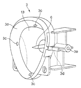
Figures 3 illustrates a first capsule engagement member 13 and Figure 4
illustrates a
capsule 1 able to be used with said first capsule engagement member according
to the system
CA 02799644 2012-11-16
WO 2011/144479 PCT/EP2011/057423
of the present invention. The first engagement member 3 presents a hollow bell
member 13.
The capsule presents an enclosure outer shape 1 a that is conformal to at
least a portion of the
hollow bell member 13. At the rear end of the first capsule engagement member
3 opening
means of the capsule, usually a hollow needle 6, is fixed for piercing the
capsule and injecting
5 water. The first engagement member 3 also comprises retaining means able to
exert frictions
with discrete parts of the outer shape 1a of the enclosure of the capsule.
These means can be
discrete bumps 3c placed at different places of the first engagement member
internal shape
periphery. They can be supported by an annular seal 3d fixed on the edge of
the hollow bell
member 13. This seal can help at improving the engagement of the first second
engagement
10 member with the rim 1 b of the capsule and avoiding leaking of water that
could flow between the
dome shaped member 13 and the external face of the capsule during the beverage
production.
The seal and the bumps are preferably made of a flexible and resilient
material. Then the seal
can then be flattened against the rim of the capsule during the beverage
production step. The
bumps 3c can deform themselves when the first engagement member engages the
capsule.
The fact that the bumps 3c are placed face to face on different sides of the
internal face of the
bell shape member 13 improves the way to retain the capsule and avoids that
the latter falls
from the first engagement member on the way to the capsule discharge position.
The fact that
the bumps 3c are placed on discrete places of the internal face of the bell
shape member 13
avoids the risk that the capsule may stick to said internal face if the
customer does not rapidly
discharge the capsule after the beverage production. The seal and the bumps
can be made of
an elastomeric material, for example a silicone or an EPDM (ethylene propylene
diene
monomer) rubber. In Figure 3, four bumps 3c are present positioned by pair on
opposite side of
the internal face of the hollow bell member 13. The bumps of the first pair
are placed at the top
and at the bottom of the internal face of the hollow bell member 13, whereas
the bumps of the
other pair are symmetrically opposed in view of the symmetrical vertical plane
of the capsule or
of the hollow bell member 13. Due to the fact that the capsule enclosure outer
shape 1 b is
conformal to the hollow bell member 13 internal surface, the bumps 3c retain
the capsule inside
the first capsule engagement member when said member moves to the capsule
discharge
position.
The capsule 1 also comprises a size such that at least a part of its rim 1 b
extends beyond
at least a part of the first capsule engagement member 3 once the capsule is
engaged in the
first capsule engagement member. Figure 5a illustrates a back view of the
first capsule
engagement member 13 with the capsule 1 engaged in the hollow bell member 13.
Some parts
of the rim 1 b of the capsule extend beyond the limits of the first capsule
engagement member. It
CA 02799644 2012-11-16
WO 2011/144479 PCT/EP2011/057423
11
is preferable that at least a vertical part of the rim lb extends beyond the
limits of the first
capsule engagement member. The term vertical is to be interpreted according to
the position of
the capsule inside the module.
The first capsule engagement member 3 also comprises means for coupling 3e
said
member to means of displacement and means 3d for cooperating with the pre-
fixation means
provided at a lateral side of the capsule cage and means 3d designed to engage
with the rim 1 b
of the capsule for fixation of the capsule close to the second engagement
member. In the
present specification the term cage designates the hollow bell shaped member.
Figure 5b illustrates a front view of the first capsule engagement member 13
and the
capsule 1 engaged in the hollow bell member 13. The bumps 3c are illustrated
in dotted points.
Figures 6a-6e illustrates the steps of introducing the capsule in the first
and second
engagement members 3, 4.
According to this aspect the capsule 1 is pre-positioned by pre-fixation means
, such as
for example flexible capsule pre-fixation arms 12. When seen from above the
arms 12 are
provided at the lateral sides of the capsule. The flexible arms 12
respectively present a vertical
groove 31 made to engage with the rim lb of the capsule 1. Therefore, when the
capsule 1 is
inserted manually by a user from the top of the beverage production module, it
will be initially
pre-positioned and held in place by the flexible arms 12. When the first
engagement member 3
is made to approach the second engagement member 4, the prefixed arms 12 are
moved away
making the capsule 1 leave the pre-fixation position in the vertical grooves
31 and pushing the
capsule 1 against the second engagement member as shown in figure 6c To this
regard means
can be provided to actively disengage the rim lb of the capsule with the pre-
fixation means
(flexible arms) 12. As shown particularly in figure 6b and 6c, the first
engagement member 3 can
be operatively connected to disengagement means 32 which cooperate with a
slanted surface
33 of the flexible arms 12 in order to push the flexible arms 12 to the
outside and thus to
disengage the vertical grooves 31 of the flexible arms 12 from the rim 1 b of
the capsule. Thus,
when the front surface of the bell-shaped member 13 of the first engagement
member 3 is
taking over the positioning of the capsule 1, the capsule 1 is made to be
disengaged from the
flexible arms 12 serving as pre-fixation means (figure 6c). In the beverage
production position as
shown in figure 6c, the rim of the capsule 1 is pushed behind the grooves 31
of the flexible arms
12.
Now, when after completion of the beverage production the first engagement
member 3 is
CA 02799644 2012-11-16
WO 2011/144479 PCT/EP2011/057423
12
moved rearwards (from figure 6c to 6d) and the capsule 1 is only held by a
frictional
engagement of the perforation member 6, the disengagement member 32 of the
first
engagement member 3 will again cooperate with specifically designed surfaces
of flexible arms
12 in order to spread these arms 12 and thus have the capsule 1 pass these
arms 12 without
being engaged by the arms 12.
Figures 6d and 6e represent the intermediate position between the beverage
production
position and the capsule discharge position wherein tabs 12b retain the part
of the capsule rim
1 b extending beyond the capsule engagement member 3. These tabs can be fixed
to the flexible
arms 12 or other part of the module 3 or the beverage machine housing. Figure
6e illustrates the
position where the tabs 12b have retained the capsule rim lb whereas the
capsule engagement
member 3 continues its return to the final position such as illustrated in
Figure 6a.
Figures 7a-7c illustrates the steps of disengaging the capsule from the first
and second
engagement members 3, 4, and discharging the capsule 1 according to another
embodiment
thant the one illustrated in Figures 6a-6e. Each figures 7a-7c presents a top
and side view of the
first engagement member 3, the capsule 1 and the pre-fixation arms 12. Figures
7a relate to
these elements placed in the beverage production position. In the precedent
step of insertion of
the capsule in the module and engagement of the capsule by the first and
second capsule
engagement members, the pre-fixation arms 12 were pushed away from the capsule
rim 1 b due
to the engagement of the cooperating means 3d of the first capsule engagement
member 3 with
a slanted portion 12a of the pre-fixation means. The size of the rim 1 b of
the capsule is designed
so as not be too large so as to enable the back movement of the capsule
without engaging the
pre-fixation arms.
Figures 7b represent the intermediate position between the beverage production
position
and the capsule discharge position wherein tabs 12b fixed to a part of each of
the flexible arms
of the pre-fixation means 12 retain the part of the capsule rim extending
beyond the capsule
engagement member. These tabs can be fixed to other part of the module or the
beverage
machine housing. Preferably, the tabs are positioned to retain the capsule rim
lb where the
opened face of the hollow bell member 13 is oriented downward.
Figures 7c represent the final position of the capsule discharge position
where the capsule
1 has been discharged from the first capsule engagement member by the two
pairs of tabs 12b
fixed each of the flexible arms of the pre-fixation means 12 and where the
first capsule
engagement member 3 finished its movement by a swivelling movement.
According to the system of the present invention the capsule must present a
rim
CA 02799644 2012-11-16
WO 2011/144479 PCT/EP2011/057423
13
sufficiently large to be retained by the pre-fixation means and by the means
for engaging the rim
when the capsule is moved to the capsule discharge position, but not too large
to be able to not
be engaged by the pre-fixation means during the back movement to the capsule
discharge
position. The capsule must also present an enclosure external shape such that
at least discrete
parts of said enclosure are submitted to friction by the retaining means of
the capsule cage
when the capsule is engaged in the latter.