Note: Descriptions are shown in the official language in which they were submitted.
CA 02799662 2012-11-16
WO 2011/144590 PCT/EP2011/057926
- 1 -
"CONTINUOUS CASTING DEVICE AND RELATIVE METHOD"
* * * * *
FIELD OF THE INVENTION
The present invention concerns a continuous casting device and the relative
method.
In particular, the present invention concerns the continuous casting of steels
of
different types, for example commercial steels, steels with a high carbon
content,
medium alloy steels or other, in which specific containing and guide devices
are
used, and can possibly be replaced, disposed at exit from the
crystallizer/ingot
mold in relation to the casting speed, which can vary according to the type of
steel as above.
The invention also concerns containing and guide devices for a cast product
comprising elements to reduce the heat losses associated with roll elements to
guide and transport the cast product located at exit from the ingot mold.
BACKGROUND OF THE INVENTION
A continuous casting device normally provides an ingot mold comprising a
crystallizer inside which the liquid metal is cast, and a series of containing
and
guide elements, such as rolls or other similar means, which accompany the at
least partly solidified cast product, and during the step of progressive
solidification, between the exit from the ingot mold and the first elements
that
make up the rolling line, for example shears, a heating furnace, a first
roughing
cage or a rolling train.
Normally, the segment at exit from the ingot mold is curved, so as to connect
the vertical or sub-vertical direction along which the casting is carried out
and the
horizontal direction in which rolling is performed.
By cast product, here and hereafter in the description, we mean a slab, a
bloom
a billet of various sizes and section.
Examples of such containing and guide elements can be seen for example in
US-A-5.630.467, where there are segments of rolls that have a progressively
increasing section as they are distanced from the exit of the ingot mold, and
mobile toward and away from the cast product, and curved continuous segments
that accompany the completely solidified product and dispose it on the
horizontal
plane so as to send it to the rolling passes.
CA 02799662 2012-11-16
WO 2011/144590 PCT/EP2011/057926
- 2 -
The presence of mobile roll elements at exit from the crystallizer is
necessary
so as to perform the soft reduction procedure, or reduction in thickness with
liquid core, where the cast product is reduced in thickness, exploiting the
fact that
its inner core is not yet completely solidified.
Document US 6.892.794 B2 shows a casting device in which, at exit from the
ingot mold, there are consecutive segments of rolls that accompany the cast
product in the step of progressive solidification, and in which the elements
that
support the cast product modify their conformation as the progressive increase
in
thickness of the solidified part of the product varies.
Normally, these containing and guide elements cooperate with so-called
secondary cooling systems, to distinguish it from the primary cooling that
takes
place inside the ingot mold. Such secondary cooling systems contribute to
define
the solidification profile of the cast product, allowing to regulate the
position of
the so-called "kissing point", that is, the point where the two solidified
semi-
skins of the cast product meet, for example as a function of the type of
material
and the final result to be obtained.
In the field of continuous casting it is also known, however, that as the type
of
steel to be produced varies, it is necessary to consequently adjust the
casting
parameters, in particular the speed of extraction of the product.
It is for example known that certain steels, for example so-called commercial
steels, are cast at relatively high speeds, up to 6-7 m/min, while for other
steels,
for example high carbon content steels, medium alloy steels and others, the
speed
must be reduced to values in the range of about 3-4 m/min.
When the casting speed passes from the higher value to the lower value, the
metallurgical length is proportionally reduced, even by 6-10 meters, and
therefore, after the so-called kissing point where the metallurgical cone is
closed,
the cast product has to travel a longer segment and also at a lower speed,
with a
relative greater temperature loss compared with higher casting speeds.
This temperature loss entails a high waste of energy and also limits rolling
fitness in terms of compression percentage downstream of the continuous
casting.
DE 102 36 368 shows containing segments with rolls that can be equipped
with heat insulation panels, for example vertical, disposed around the transit
path
of the cast product.
CA 02799662 2014-02-27
- 3 -
The purpose of the present invention is therefore to solve this shortcoming,
proposing a solution that allows to adjust the heat conditions of the cast
product at
exit from the ingot mold to the variations in the casting speeds deriving, for
example
but not only, from modifications in the type of steel that is being cast.
Another purpose of the invention is to obtain this adjustment with a
relatively
simple and efficient solution which does not entail any extension of the
casting line
and that does not require the use of additional elements that modify the
trajectory
and/or bulk of the casting machine.
The Applicant has devised, tested and embodied the present invention to
overcome
the shortcomings of the state of the art and to obtain these and other
purposes and
advantages.
SUMMARY OF THE INVENTION
In accordance with the above purposes, the invention provides that, in a
continuous casting machine comprising a casting unit of the substantially
traditional
type, with an ingot mold/crystallizer, and a containing, guide and possibly
cooling
unit, located at exit from the casting unit, at least part of the containing,
guide and
possible cooling elements are replaceable in relation to the variation in
casting speed
that may depend, for example but not only, on the type of steel that is being
cast.
More particularly, the invention provides a first type of containing, guide
and
possible cooling unit, which comprises containing and guide rolls for the cast
product
associated with a substantial part of the at least partly curved path that
connects the
exit of the casting unit to the horizontal segment that then leads to rolling,
and at least
a second type of containing and guide unit which comprises, instead of part of
the
rolls, one or more insulating and/or thermally heated panels, for example but
not only
insulated and/or with a reflecting surface and/or heated for example by
electric
resistances.
According to the invention, the insulating and/or thermally heated panels are
used
in the case of relatively low casting speeds, for example in the range of 4-5
meters/minute, to replace part of the normal containing and guide rolls that
are
CA 02799662 2012-11-16
WO 2011/144590 PCT/EP2011/057926
- 4 -
used for higher casting speeds, in order to reduce as much as possible the
temperature losses due to the longer time that the completely solidified
product
takes to exit from the continuous casting machine.
According to the invention, thanks to using these insulated and/or reflecting
panels, it is possible to reduce the overall temperature loss by 50% and even
more than 90% if the panels are heated, for example electrically; in this way
the
reduction in speed deriving from the different type of steel cast is
compensated.
Furthermore, given the reduced number of containing and guide rolls in
contact with the cast product, losses by conduction deriving from said contact
are
also reduced.
According to the invention, moreover, the length of the casting machine
remains unchanged using the first or the second type of containing, guide and
possible cooling unit, inasmuch as no auxiliary elements are inserted in
addition
to those already present on the line, and only segments of the roll only type
are
replaced by segments partly made up of panels, and vice versa.
The replacement of the segments may be performed manually or automatically
by means of suitable robots or similar or comparable systems, during the
downtimes of the line required for modifying the type of product to be cast
and/or for configuring the line.
BRIEF DESCRIPTION OF THE DRAWINGS
These and other characteristics of the present invention will become apparent
from the following description of a preferential form of embodiment, given as
a
non-restrictive example with reference to the attached drawings wherein:
- fig. 1 is a schematic view of a segment of a casting line in which the
present
invention is applied;
- fig. 2 is a perspective view of a guide and containing segment used in
the
present invention;
- fig. 3 is a lateral section of the guide and containing segment in fig.
2.
To facilitate comprehension, the same reference numbers have been used,
where possible, to identify common elements in the drawings that are
substantially identical. It is understood that elements and characteristics of
one
form of embodiment can conveniently be incorporated into other forms of
embodiment without further clarifications.
CA 02799662 2012-11-16
WO 2011/144590 PCT/EP2011/057926
- 5 -
DESCRIPTION OF A PREFERENTIAL FORM OF EMBODIMENT
With reference to fig. 1, a curved continuous casting line 10 is shown
schematically, comprising a crystallizer 11 suitable for casting slabs, blooms
or
billets, identified generically by the reference number 12 to denote the cast
product.
The curved casting line connects the crystallizer 11 disposed vertically with
the rolling line disposed horizontally, of which a first roughing stand 13 is
shown, to give a non-restrictive example.
The system for conveying the cast product 12 comprises a plurality of roll-
type guide and containing segments, indicated generically by the reference
number 14, the function of which is to accompany the cast product 12 along the
curved line, determining in a substantially known manner its progressive
cooling
and solidification, so as to determine the closure of the metallurgical cone,
based
on the type of steel and consequently on the casting speed.
As the casting speed varies, for example passing from a speed of about 7
meters a minute to a speed of about 4 meters a minute, the cast product 12
must
travel, after the point of closure of the metallurgical cone, a longer segment
at
low speed with relative temperature loss.
In this case the invention provides that one or more of the guide and
containing segments 14 can be replaced by guide and containing segments 15 of
a mixed type with panels and rolls, an example of which is shown in figs. 2
and
3.
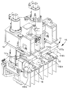
The guide and containing segments 15 comprise guide rolls 16 disposed on at
least one side (extrados side) to guide and accompany the cast product 12 as
it
advances, while on the opposite side there are insulated and/or reflecting
and/or
heated panels 17, the function of which is to reduce the temperature loss of
the
cast product 12 transiting at low speed.
More specifically, in the solution shown, the upper side (or intrados) of the
guide and containing segment 15 comprises a first panel 117a at entrance, an
intermediate roll 116a and a second panel 117b at exit from the segment.
The side of the panels 117, 117b facing toward the intermediate panel 116a is
inclined in order to leave uncovered as little space as possible of the
surface of
the cast product 12 in transit during its passage through the guide and
containing
CA 02799662 2012-11-16
WO 2011/144590 PCT/EP2011/057926
- 6 -
segment 15.
The presence of a single intermediate roll 116a, which is however
advantageous to guarantee the correct guide of the cast product 12, for the
whole
upper side (intrados) of the containing and guide segment 15, reduces to a
minimum the temperature losses due to the contact between the surface of the
product 12 and the surface of the roll 116a.
On the lower side (or extrados) of the containing and guide segment 15, where
the weight of the cast product 12 in transit rests, there are a plurality of
rolls
116b, four in this case, which guide and contain the cast product 12 during
its
advance.
The rolls 116b have a lesser diameter than traditional rolls, and in an
intermediate position between them there are insulated and/or reflecting
plates
18, which also have the function of reducing to a minimum the temperature
losses of the cast product 12 during its transit at low speed through the
containing
and guide segment 15.
The plates 18 are triangular in shape with the long side facing toward the
lower surface of the cast product 12 in transit.
The triangular shape, inclined downward, facilitates the discharge of the
scale
that detaches from the cast product; the non-accumulation of scale on the
plates
18 allows to keep their insulating function practically unchanged over time.
It is clear that, although the solution shown represents a mixed configuration
of rolls/panels that is extremely valid from the point of view of heat
containment,
other mixed solutions of panels/rolls may equally be adopted and may have an
effectiveness comparable to the one shown, which therefore serves only as a
non-
restrictive example.
The segments 14 of a known type, consisting completely of rolls, and the
segments 15 of the mixed type with panels and rolls have an external bulk,
defined by the relative support frame 19, substantially identical to each
other, so
that they are totally replaceable with respect to each other without
determining
extensions or shortenings of the casting line, since no auxiliary or
additional
elements are required.
If the configuration of the continuous casting machine is changed, for example
to pass from one type of steel that can be cast at a speed for example of 6-7
CA 02799662 2012-11-16
WO 2011/144590 PCT/EP2011/057926
- 7 -
m/min or more to a type of steel that requires a lower casting speed, for
example
4-5 m/min or less, one or more of the containing segments 14 can be replaced
by
one or more containing segments 15 of the mixed panels/rolls type, with manual
or automatic systems, to adapt the curved casting line to the various
requirements
of heat protection.
Such replacement may be performed by manipulator robots or, if it is not
possible to use robots, by means of bridge cranes, and may last for the time
required for the change in configuration, so that it can be carried out
without
causing any slowdowns in production.
The panels 117a, 117b may be made of metal covered by reflecting paints, or
other suitable material of a known type.
According to a variant, the panels 117a, 117b incorporate or are covered by
mirror elements, for example sheets of steel, to increase the reflecting
effect.