Note: Descriptions are shown in the official language in which they were submitted.
CA 02800399 2012-11-09
1
URBAN TRANSPORT INSTALLATION USING TRACK ROPES
Fieldof the invention
'he invention refers to an overhead public transport
inst a:lation for urban and peri-urban environments comprising
veh i c.es rolling on track ropes between overhead stations
above the road transport system.
State of the art
'he creation of a new means of overhead public transport
in the urban fabric above the existing road transport system
obvi oisly poses a number of problems of integration, notably
of its stations for limiting their bulkiness at places where
noth irg has been provided for this purpose. Moreover, such a
means of transport has never been taken into account in town
planning projects.
Moreover, the access of passengers to the vehicles in a
station from the sidewalks on both sides of the urban roads
will result in an increase in their crossing and a more
considerable traffic interruption, this trouble being more
noticeable when the stations are located at crossroads.
The operation of the overhead transport lines imposes some
constraints regarding the situation of the boarding and/or
disembarkation platforms which do not very often coincide with
the available places on the sidewalks for a direct access to
the platforms.
CA 02800399 2012-11-09
2
Object of the invention
The object of the invention is to create a station
spanning the road transport system and provided with a more or
less large platform according to the need, above the overhead
clearance of the road transport system and below the level of
the boarding and/or disembarkation platforms while taking
advantage of the height of the sags in the track ropes which
heighten accordingly the level of the station platforms with
respect to the overhead clearance to be respected.
The surface of the platform can be variable according to
the type of stations, while being formed either by a simple
footbridge between two pillars facing each other on both sides
of the road transport system or by a real pedestrian square
above a crossroad of several roads, which even enables to
design, in a rational way, connecting stations for several
transport lines crossing above the platform at different
levels.
Furthermore, in addition to ensuring in a functional way
the change of level of the passengers, the development of a
public transport station must take into account, with regard
to the users, their circulation, their waiting during a peak
period, the points where tickets are sold or checked. These
various constraints require to find dedicated areas that can
be large in the event of dense traffic, which can be very
voluminous, very difficult to find at the level of the road
transport system and expensive at the upper level of the
boarding/disembarkation of passengers.
The obligations to ensure the correct operation of such a
means of overhead public transport, with the constraints
CA 02800399 2012-11-09
3
inherent to the integration into an urban fabric which is not
flexible and congested, thus result in finding new functional
arrangements.
The platform of a station according to the invention is
located under the level of boarding/disembarkation of
passengers, and above the overhead clearance of the road
transport system because of the sag in the track ropes. The
pillars located outside the road transport system support the
platform and comprise means of access to the platform from the
sidewalks.
Thus the platform according to the invention:
- is freely open to pedestrians and users,
- allows users only to reach the upper overhead transport
level and in an essential way,
- reconstitutes all the areas necessary for the good
operation (in particular when the traffic is dense) of the
transport system, which is impossible to find at the ground
level,
- ensures, on the one hand, regarding pedestrians, a sure
means of crossing the roads, and on the other hand, regarding
traffic, an improvement thanks to a reduction in the number of
pedestrian crossings.
According to a feature of the invention, there are two
pillars on both sides of the station, and the means of access
preferably comprise elevators leading to the intermediate
level of the footbridge and the upper level of the
boarding/disembarkation platforms.
According to a feature of the invention, each pillar is
provided with two elevators in order to ensure the
availability of operation.
CA 02800399 2012-11-09
4
According to another feature, the elevators have doors
perpendicular to the installation tracks allowing a pedestrian
circulation at all the levels, in particular at the level of
the road transport system.
The platform according to the invention can comprise first
free zones of use for pedestrians, and second zones only for
the users of the public transport, and comprising a number of
services.
The users can reach the upper boarding level from the
lower level of the road transport system via a first free
access way leading to the platform from places outside the
traffic, and the dedicated boarding/disembarkation gates of
the public transport from the platform via a second access way
for users only.
Regarding this second access way, the elevators can be
provided with automatic doors opening at the upper level
facing and against those of the vehicle. The elevator car thus
has a triple function of double-entrance security door,
vertical transport and platform. By this means, there is no
plate above the platform, which reduces considerably the
visual impact of the station.
In the case of a vehicle having two side doors on the
opposite sides, the access to the vehicle is given by two
elevators, one for boarding, and the other for disembarking.
Brief description to the Figures
CA 02800399 2012-11-09
Other advantages and features of the invention will more
clearly arise from the following description of various
embodiments of the invention given as examples and represented
in the annexed drawings, in which:
5
Figure 1 is a line profile of an installation using ropes
and provided with a station according to the invention;
Figure 2 is a cross view of a station according to the
invention for an installation comprising two vehicle running
tracks at the same level;
Figure 3 is a top view of the platform level in Figure 2;
Figure 4 is a top view of the footbridge level in Figure
2;
Figure 5 is a top view of the road transport system level
in Figure 2;
Figure 6 represents a top view of a town square including
a junction of two avenues with accesses to the platform
according to the invention;
Figure 7 represents a top view of two overhead transport
lines located above the running tracks and crossing at
different levels, with the stopping position of the vehicles,
and their contiguous vertical access from the platform;
Figure 8 represents a top view of the platform with the
locations of the accesses from the sidewalks corresponding to
Figure 6, and the accesses for the boarding/disembarkation
CA 02800399 2012-11-09
6
into/from the idle vehicles of the two overhead lines at
different levels, corresponding to Figure 7;
Figure 9 represents a front view of the superposition of
the different levels in Figures 6, 7 and 8.
Description of the invention
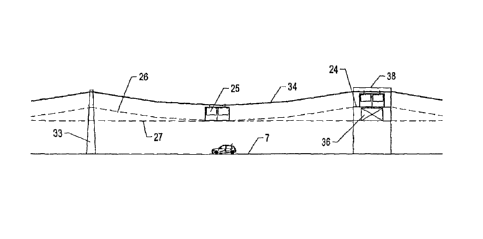
Figure 1 represents a line profile of an installation
using track ropes 34 on which a vehicle 25 circulates, in
particular a cablecar, along a trajectory 26 above the level
of the road transport system 7. The footbridge 36 or platform
is placed under the level of the platforms 24 of a station 38,
which must be higher than the overhead clearance 27 because of
the sag in the track ropes.
Figure 2 represents a station 2 in which vehicles 3 and 4,
each of them running in a different direction, stop in front
of the boarding platforms 5. The station 2 comprises two
pillars 8 located on both sides of the road transport system 7
and supporting a platform 6 located under the levels of the
platforms 5 it supports via posts 1. The accesses to the
platform 6 and boarding platforms 5 from the road transport
system 7 are represented by two different systems which are
elevators 9 or staircases 10 integrated in the pillars 8.
According to the span of the platform 6, there may be one or
more intermediate supports 11 which can also be used as
support for possible platforms 12 located between the two
running tracks for the vehicles 3 and 4.
Figures 3, 4 and 5 are top views of the various levels of
a station 2 according to Figure 2. The doors of the elevators
9, located in one of the pillars 8, are advantageously
= CA 02800399 2012-11-09
7
arranged so as to allow a rational access of the users in the
longitudinal direction of the road transport system 7, Figure
showing the possibility of accessing to the elevators while
encroaching at a minimum upon the sidewalk width.
5
Figure 6 represents an intersection of two avenues 100
forming the road transport system 7 between the buildings 114
of an urban zone, which avenues are bordered by sidewalks 101
on which pedestrians can walk. These pedestrians can reach the
platform 6 according to the invention, represented here in
dotted lines in the center of the intersection of the two
avenues 100, through accesses 102, advantageously formed by
elevators 9, escalators 115 or staircases 10, located at
strategic places on the sidewalks 101.
Figure 7 represents an overhead transport line 105
crossing a second overhead transport line 110 located at a
higher level. The stopping places of the vehicles 108, 109
running on the line 105 are contiguous with their vertical
accesses 111, 112 from the level of the platform 6. In the
same way, the stopping places of the vehicles 103, 104 running
on the line 110 are contiguous with their vertical accesses
106, 107 from the level of the platform 6.
Figure 8 is a top view of the level of the platform 6 on
which is arranged a zone 113 for the users of the urban
transport who use the vertical accesses (106, 107, 111, 112)
for the boarding/disembarkation into/from the idle vehicles
(103, 104, 108, 109) of the two lines (105, 110).
Figure 9 represents a station 120 in which vehicles 108,
109, each of them running in a different direction on the
overhead track 105, stop in front of their respective vertical
CA 02800399 2012-11-09
8
boarding/disembarkation accesses 111, 112 and vehicles 103,
104, each of them running in a different direction on the
overhead track 110 located at a higher level, stop in front of
their respective vertical boarding/disembarkation accesses
106, 107. The station 120 comprises two pillars 8 located on
both sides of the road transport system 7 and supporting a
footbridge 6 located under the level of the tracks 105, 110.
The accesses to the platform 6 from the road transport
system 7 are represented by two different systems which are
elevators 9 or escalators 115 integrated in the pillars 8. One
can reach the vehicles 103, 104, 108, 109 from the platform 6
through the corresponding vertical accesses 106, 107, 111,
112.
According to an alternative embodiment, each vehicle has
two side doors on the opposite sides, the
boarding/disembarkation into/from two successive vehicles
being performed alternatively via two elevators, one for the
doors on one side of the vehicle and the other for the doors
on the other side.