Note: Descriptions are shown in the official language in which they were submitted.
CA 02800400 2014-02-12
1
AN APPARATUS TO DECONTAMINATE EQUIPMENT
CONTAINING INTERNAL CHANNELS
FIELD OF THE INVENTION
[0001] The test apparatus of the present invention is a self contained unit
and
system for determining whether medical equipment or devices such as
endoscopes, minimally invasive surgical instruments (MIS), etc., are blocked,
or
substantially free flowing, or are disconnected or leaking before they are
subjected to cleaning and/or a disinfecting process that is either sequential
or
simultaneous. The apparatus
has a manifold that generally receives
predetermined amounts of a gas and/or liquid for dispensing to one and
preferably a plurality of channels. Advantageously, the test apparatus of the
present invention can be utilized as a stand-alone unit that is able to
monitor the
noted medical equipment or devices with regard to the flow of a gas and/or
liquid
therethrough such as large or small lumens and such flow can also be
automatically verified by a system independent of human intervention.
Alternatively, the test apparatus can be utilized as part of a comprehensive
system in conjunction with other devices for testing, cleaning, and/or
disinfecting.
BACKGROUND OF THE INVENTION
[0002] Reusable channel containing medical devices such as endoscopes,
and minimally invasive devices, are widely used for a variety of non-invasive
and
invasive surgical procedures and are noted as being difficult to decontaminate
due to lack of sufficient penetration of gas or liquid through their entire
length and
lack of sufficient contact times. Of particular concern are blockages of such
narrow devices, due to the buildup or deposition of soil that will impede the
flow
of liquid and gases, or leakage as caused by connection of the devices that
can
often go unnoticed by users and staff.
CA 02800400 2012-11-22
WO 2011/149539
PCT/US2011/000944
2
[0003] U.S. Patent 5,279,799 relates to an apparatus for cleaning and
testing
endoscopes by injecting pressurized air into the sheath and pressurized air
and
washing liquid into the ducts, and monitoring the same. A washing chamber is
provided which contains retractable cages to hold the endoscopes during
cleaning and testing. The cages include a coupler for detachably connecting
tubes supplying the air and washing liquid to the endoscopes. The cages also
have markings for automatically activating the apparatus when a cage
containing
an endoscope is inserted into the washing chamber. The apparatus further
requires a tight attachment of a connector to the said lumen to allow for the
flow
of air. With these connectors, there is a risk of occlusion of material at the
contact sites, which do not allow for adequate contact with cleaning and
disinfection chemistries during the decontamination process.
[0004] Some cleaning and/or disinfection systems utilize connectors that
can
have leakage around contact points, but the detection of adequate flow is
often
difficult. Other systems describe using liquid under pressure to permit flow
through lumens of medical devices in the absence of any connectors, but
likewise they cannot ensure that all lumens are free-flowing.
_ SUMMARY OF THE INVENTION
[0005] An independent or integral apparatus for screening, testing, and
monitoring various channel-containing medical devices comprises a hollow
manifold for receiving fluids such as air and/or liquid such as water,
cleaning
solutions, and the like. The manifold has a plurality of connectors for
attachment
to a multiplicity of devices to be tested and has one or more pressure sensors
for
determining whether a particular device is generally blocked, leaking or open
thereby permitting the free flow of fluids therethrough. One or more solenoids
control the flow of the manifold fluid either sequentially or simultaneously
to one
or more devices.
[0006] In one embodiment, the test apparatus is designed to determine if a
blockage is present in a channel of a medical device, or whether the device
contains a leak, and can also perform a cleaning operation on the device.
Tests
of multiple medical devices can be performed sequentially or simultaneously.
An
CA 02800400 2012-11-22
WO 2011/149539
PCT/US2011/000944
3
advantage of the present invention is that the test apparatus is able to
ensure the
flow of a gas and/or liquid to any channel diameter size.
[0007] In one embodiment, an integral apparatus for testing and/or cleaning
a
channel containing medical device, comprises a hollow manifold having at least
one connector, said manifold having at least one pressure sensor for
determining
the pressure therein, and a solenoid valve operatively connected to said
connector and capable of being operatively connected to said channel
containing
medical device; an airflow line having a pressure switch and a solenoid valve,
said airflow line capable of maintaining a predetermined pressure, said
airflow
line connected to said manifold; a microprocessor operatively connected to
said
airflow line pressure switch, said microprocessor also being operatively
connected to said manifold pressure sensor and operatively connected to said
airflow line solenoid valve, and said microprocessor, upon receiving a signal
from
said manifold pressure sensor detecting a pressure in said manifold, being
capable of energizing said airflow line solenoid valve and also opening said
solenoid valve connected to said connector so that said air in said manifold
is
capable of flowing into said channel containing medical device.
[0008] In a further embodiment, a method for testing a channel containing
medical device, comprises the steps of obtaining a testing apparatus
comprising
a hollow manifold having at least one connector, a solenoid valve operatively
attached to said connector and capable of being attached to a channel
containing
medical device, said manifold having at least one pressure sensor for
determining pressure within the manifold, said apparatus further including an
airflow line having a pressure switch and an airflow line solenoid valve, said
airflow line operatively connected to said manifold, said testing apparatus
further
including a microprocessor operatively connected to said pressure switch of
said
airflow line, to said airflow line solenoid valve, to said manifold pressure
sensor,
and to said connector solenoid valve; operatively connecting said connector
solenoid valve to said channel containing medical device; and opening said
airflow solenoid valve and determining the pressure in said manifold with said
manifold pressure sensor. =
CA 02800400 2014-02-12
4
BRIEF DESCRIPTION OF THE DRAWINGS
[0009] The present invention will be better understood by reference to the
following drawings wherein:
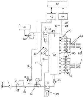
[0010] FIG. 1 is a schematic view showing a test apparatus for a channel
containing medical device wherein a plurality of connectors, contained on a
manifold, are each operatively connected to a solenoid valve assembly for
controlling the amount of fluid emitted from the manifold and into the medical
device;
[0011] FIG. 2 is a perspective view of the connector manifold of FIG. 1;
[0012] FIG. 3 is a perspective view of a further embodiment of a test
apparatus wherein the solenoid valve is external of the manifold;
[0013] FIG. 4 is a schematic view of another embodiment of a test apparatus
for a channel containing medical device similar to FIG. 1 wherein each
connector
has a pressure sensor;
[0014] FIG. 5A is a perspective view of the test apparatus embodiment of FIG.
4;
[0015] FIG. 5B is a top plan view of FIG. 5A showing manifold 20 and
individual side channel pressure sensors 62; and
[0016] FIG. 6 is an example of a graphical method used to determine the
slope and shape of function chart describing relation between pressure and
flow.
DETAILED DESCRIPTION OF THE INVENTION
[0017] While the present invention relates to test apparatuses for medical
equipment or devices having internal channels such as endoscopes, dental
equipment, minimally invasive surgical instruments, etc., it will generally be
described with regard to a preferred embodiment, i.e. a device containing a
lumen. The test apparatus is suitable for use in a variety of applications or
environments. In one embodiment, the test apparatus can be utilized as a stand-
alone device at any desired location such as in relatively close proximity to
a Sink
or drain. In a further embodiment, the test apparatus can be utilized in
conjunction with one or more additional devices or processes or combinations
thereof. For example, the test apparatus can be utilized with or in the device
described in U.S. Patent 5,279,799. The test apparatus can be utilized to
check one or more medical devices having an
CA 02800400 2012-11-22
WO 2011/149539
PCT/US2011/000944
internal channel for blockage, leakage, or as a cleaning or disinfection
apparatus,
or a combination thereof.
[0018] The test apparatus of the present invention ensures that channel
containing devices are suitable (e.g. unblocked and not leaking) for
subsequent
cleaning, disinfection, sterilization, or any combination thereof. An
embodiment
of such a test apparatus 1 is shown in FIGS. 1 and 2, and comprises manifold
20. The manifold receives a fluid, for example, a gas such as air or a liquid
such
as water and the same is admitted to manifold 20 at a predetermined pressure
generally determined by the maker of the medical equipment or device, for
example an endoscope, etc. The pressure within the manifold is generally from
about 500 or about 600 millibars (0.05 to 0.06 MPa) to about 1,000 or about
2,000 or about 5,000millibars (0.1 or 0.2 or 0.5 MPa). The embodiments of
FIGS. 1 and 2 will be first discussed with respect to an air input, then
initialization
of the test, followed by a description of the test with respect to a channel
containing device.
[0019] Manifold 20 generally contains a hollow portion or chamber wherein
the liquid (e.g. water) or a gas (e.g. air) or any combination thereof,
resides until
needed. For example, manifold 20 can contain from about 1% or about 10% to
about 90% or about 99% by volume of air with the remaining being the liquid.
In
a preferred embodiment, preferably either only air or only water is utilized,
or if a
cleansing fluid is desired, air and water containing a cleansing surfactant
can be
alternately transferred through manifold 20 to provide a pulsing effect.
Manifold
20 can be drained at the end of a test cycle.
[0020] FIG. 1 is a representation of various functional elements of the
apparatus and a process emphasizing an order of the elements and FIG. 2 sets
forth an example of a specific mechanical design.
[0021] Air Input
[0022] Integral test apparatus 1 contains compressed air source 5 that
generates air pressure as limited by pressure regulator 9, to a certain
preselected value such as about 1 bar (0.1 MPa) within manifold 20.
CA 02800400 2012-11-22
WO 2011/149539
PCT/US2011/000944
6
Downstream solenoid 21 is normally maintained in a closed position during the
initial compression of the air. Filter 7 is utilized to clean the air. The
presence of
a working pressure is confirmed by pressure switch 11 that constantly monitors
the pressure and sends a signal through electrically conductive line 15 that
is
connected to input module 42 of control unit or microprocessor 40. When the
testing apparatus is in use, the loss of the electrical signal (i.e. no
signal) to the
input module, as caused by the pressure dropping below a predetermined value,
results in a response, for example termination of a flow of compressed air and
a
display of a warning signal such as a visual signal, or an audible alert, etc.
by the
microprocessor 40.
[0023] Initialization of test apparatus 1
[0024] The test procedure is initiated in any number of ways such as by
pressing a button that is electronically connected to input module 42, by
powering up the device, or desirably by touching a screen of a display such as
a
color liquid crystal display, so that control unit 40 activates output module
44 that
energizes solenoid valve 21 through electrically conductive line 18. Valve 21
is
generally closed if not activated or energized. Once energized, compressed air
flows through pressure regulator 9, past pressure switch 11 and through a flow
mechanism such as an orifice, a Venturi tube, or a flow nozzle, embodied in
airflow measuring device 13, and through the open solenoid valve 21. The
compressed air then fills hollow manifold 20 to a desired, preselected
pressure
as well as tubes or lines located between manifold 20 and the plurality of
solenoid values 35. Depending upon the design of the test apparatus, valves 35
can either be opened, but preferably are not activated or energized and thus
are
normally closed thereby impeding the flow of the compressed air. The amount of
pressure in the manifold is theoretically equal to the pressure determined by
pressure regulator 9. However, in reality it is generally lower, such as from
about
0.1 to about 0.2 bars (0.01 to 0.02 MPa) lower, because of check valve 22.
[0025] The primary purpose of check valve 22 is to prevent any backflow,
especially when the device is in the washing phase. That is, in the embodiment
shown in FIG. 1, the manifold 20 is shared by the testing apparatus containing
compressed air as well as a washing fluid. Thus, depending upon the stage of
utilization of the testing apparatus, manifold 20 can be filled with air, or
be filled
CA 02800400 2012-11-22
WO 2011/149539
PCT/US2011/000944
7
with water, for example hot or cold, with or without detergent, etc. Wash
chamber reservoir 80, pump or motor 82, and upper solenoid valve 25 activated
by output module 44 through electrically conductive line 19, are utilized
preferably with regard to the washing cycle. Thus, check valve 22 serves to
protect any instrumentation between compressed air source 5 and check valve
22.
[0026] As shown in FIGS. 1 and 2, connectors 30 extend outwardly from the
manifold and can have ribs thereon, not shown. In lieu of ribs, any other
suitable
fastening device such as a clamp or external fastening band can be utilized.
Each connector 30 is connected to an individual solenoid valve 35 having an on-
off or open and closed position therein to admit the compressed air through
the
manifold and through an individual connector 30 to a channel containing
device.
Each connector 30 can be directly attached to a channel containing device or
through a conduit, e.g. tube 67, that can have a wide range of internal
diameters
and also different wall thicknesses, to the channel containing device.
[0027] Pressure sensor 60 of FIG. 1 measures the actual pressure inside
manifold 20 and transduces the pressure value into an electrical signal
carried
through electrical line 61 that is then read by input module 42 of control
unit 40.
[0028] At this phase of the operation, the test apparatus can perform a
self
test. That is, if the value of pressure read by pressure sensor 60 is much
lower
than the expected pressure, for example about 0.9 bar (0.09 MPa), the same
indicates a malfunction somewhere in the system such as the compressed air
source 5, pressure regulator 9, any of valves 35, etc., or a loss of
electrical
connection between pressure sensor 60 and input module 42, and the like.
During initialization of the test, the pressure difference directly before and
after
airflow measuring device 13 is measured. Since there is a relation between the
flow value and the value of the differential pressure of device 13, the value
of the
airflow can be readily determined. This value is then transduced into an
electrical signal that flows through electrically conductive line 17 that is
then read
by input module 42 of control unit 40. After the transitional phase of filling
the
testing apparatus, and especially manifold 20, the airflow value should be
zero.
If not, then the same is an indication that there is leakage in the system or
some
of the valves 35, etc., are not properly closed. Control unit 40 compares the
pressure and flow values to determine the airflow value.
CA 02800400 2012-11-22
WO 2011/149539
PCT/US2011/000944
8
[0029] Flow Test of Individual Channel Containing Devices
[0030] After the manifold is filled with compressed air and an optional
self-test
has been completed, i.e. and it is determined that there is no leakage in the
system, etc., a control is activated that through electrically conductive line
23
energizes a specific solenoid 50 that opens a preselected valve 35 of the many
valves shown in FIG. 1. Airflow line solenoid 21 is also energized or opened.
The compressed air can then freely flow from air source 5 through flow line 10
into manifold 20 and then into the opened predetermined solenoid valve 35 and
into a channel containing medical device 65 such as an endoscope attached via
connection line 64 to the open valve. The airflow and the pressure maintained
inside the manifold are influenced by the diameter and length of the channel
containing device being tested. Once the transitional phase of transferring
compressed air into the channel containing device has stabilized, e.g. a
constant
pressure value is maintained, the flow value of device 13 is read by control
unit
40 and compared with a value that is stored within an internal memory of
control
unit 40. Such stored values of airflow and/or pressure can be readily
determined
in a manner known to the art and to the literature, with regard to various
different
sized channel containing devices, diameters, and the like. If the airflow
value of
device 13 is similar to the predetermined value, a channel containing device
is
considered to be open or clear. If the value is lower than the predetermined
value, the channel containing device is then generally considered to be
blocked.
If blocked, the channel containing device is removed and maintenance thereon
is
conducted to remove the blocking material. If the airflow value is higher than
the
predetermined airflow value for the channel containing device, the same
generally indicates that there is either not a proper air-tight connection
between
the channel containing device and the open valve, or that the channel
containing
device may be leaking. In such a situation, naturally the cause of the
excessive
flow rate is determined and repaired.
[0031] An alternative procedure to determine the airflow through the
channel
containing device is to utilize pressure sensor 60 located on manifold 20 as
shown in FIG. 2. The value of the pressure determined by pressure sensor 60
can be compared to the predetermined control unit value, or the pressure value
from sensor 60 can be combined with the airflow value of device 13 using a
mathematical formula to determine a suitable pressure within a particular
channel
CA 02800400 2012-11-22
WO 2011/149539
PCT/US2011/000944
9
containing device being tested. If the value of the pressure within manifold
20 is
above a predetermined value, i.e. generally equal to the pressure permitted by
pressure regulator 9, the channel containing device is blocked. If the
pressure is
lower, then either the channel is leaking, and/or there is a leak in the
connection
between the channel containing device and the open valve. If the pressure is
relatively equal to the calculated pressure, the channel containing device is
clear.
[0032] Once a particular channel containing device has been tested as
indicated above, it can be removed with the particular individual solenoid 50
closing its respective internal valve 35 (not shown). The procedure is then
repeated with respect to other channel containing devices attached to other
solenoid valves 35 that are controlled by their respective solenoids 50.
[0033] The testing apparatus of FIGS. 1 and 2 is designed generally to test
one channel containing medical device at a time. Thus, once the test is
finished,
a second channel containing device can then be immediately tested as well as
the remaining channel containing devices in quick succession. During the
course
of testing the subsequent channel containing device, the previously tested
channel containing devices can be removed and a new channel containing
device attached thereto for testing.
[0034] While the invention has been described with regard to channel
containing devices, it is to be understood that any type of tube, conduit,
hose,
endoscope, etc. having a wide range of internal diameters and also of
different
wall thicknesses can be tested with regard to blockage, and the like.
[0035] Once testing is completed, if so desired, the various channel
containing devices, conduits, can be subsequently washed. Washing is readily
obtained by pumping a washing fluid, for example water and a detergent, from
wash chamber reservoir 80 via pump or motor 82 through solenoid valve 25
located on connection line 24 that is in the open position into manifold 20
and
subsequently into the various channel containing devices upon the opening of
individual valves 35 upon a signal from its respective individual solenoid 50.
Due
to the existence of check valve 22, the wash fluid will not enter into the
compressed air source line 10.
[0036] While the invention has been described with regard to the
specifically
above-noted pressure, any amount of pressure can be utilized to be admitted to
a particular conduit, tube, and the like. For example, as noted above,
pressure
CA 02800400 2012-11-22
WO 2011/149539
PCT/US2011/000944
can range from about 1 bar (0.1 MPa) to about 5 bars (0.5 MPa) and desirably
from about 1 bar (0.1 MPa) to about 2 bars (0.2 MPa).
[0037] It is an aspect of the present invention that the various pressure
readings or airflow readings as determined by pressure sensor 60 or airflow
mechanism 13 can be determined visually, i.e. by simply reading a gauge or by
an audible signal such as a buzzer or alarm, etc, that is calibrated to
activate
upon exceeding a preselected or predetermined fluid pressure value or range,
or
by falling below such an indicated suitable range, or preferably both. Since,
as
noted, manifold 20 is connected to every individual connector 30 and to every
valve 35, each medical device such as an endoscope connected to each
solenoid can be sequentially tested. Depending upon the medical device being
tested, different limits with regard to unsuitable or undesired high pressure
as
well as low pressure readings can be set and such limits can vary from device
to
device. Thus, for one device, an unsuitable pressure reading can vary from
greater than or less than 10% of a selected value and with respect to another
device it can vary from greater than or less than 15% of a desired pressure
value and so forth. If a channel containing device is partially or totally
blocked, it
can be cleaned in a manner as noted above or can be cleaned as by subjecting
it
to a series of pulses or blasts of water, or air, or combinations thereof.
[0038] FIG. 3 is similar to FIG. 2 and shows an example of a manifold 20
having pressure sensor 60 thereon as well as an input line having check valve
22
thereon. Unlike FIG. 2 which has valves 35 integral with the manifold 20 and
connectors 30 are connected to a channel containing device (not shown), the
embodiment of FIG. 3 has external valves 35 and solenoids 50 that are
connected to the manifold block via a connecting tube 67. For sake of clarity,
while only one such connecting tube is shown connected to channel containing
device 65, it is to be understood that all connectors 30 can have a connecting
tube 67 thereon, each connected to a different channel containing device 65.
The manifold block of FIG. 3 is similar to that of FIGS. 1 and 2 and is thus
connected in the same manner with respect to all the connection lines, control
unit 40 having input module 42 and output module 44, and the various devices
or
elements contained on air input line 10 as set forth in FIG. 1. Of course, the
mode of operation and testing of the individual channel containing devices and
all
CA 02800400 2012-11-22
WO 2011/149539
PCT/US2011/000944
11
other aspects is the same and is not repeated but hereby fully incorporated by
reference with respect to FIGS. 1 and 2.
[0039] Another embodiment of the present invention as set forth in FIGS. 4,
5A and 5B is essentially identical to that set forth in FIGS. 1 and 2 and
hence will
not be repeated but is hereby fully incorporated by reference. Summarizing,
the
test apparatus of FIGS. 4, 5A and 5B, they contain the same air compressor
source 5 and flow line 10 having the same devices such as pressure regulator
9,
pressure switch 11, airflow measuring device 13, solenoid 21 and check valve
22
as in FIG. 1 along with the same connecting lines 15, 17, and 18 as in FIG. 1.
The optional washing system comprising wash chamber reservoir 80, wash
pump or motor 82, and solenoid valve 25 is also identical. Through the
electrical
lines data and information are transmitted to input module 42 or electronic
control
unit 40. Output module 44 of the control unit sends information such as a
signal
to individual solenoids 50 to open and close valves 35. As with FIG. 1, the
embodiments of FIGS. 4, 5A and 5B relate to the operation of one individual
solenoid and one corresponding individual valve to test an individual channel
containing device separately while all remaining valves are closed. However,
unlike the embodiments of FIGS. 1 and 2, embodiments of FIGS. 4, 5A and 5B
contain additional pressure sensors 62 located within or on manifold block 20.
That is, as shown in FIG. 5A and 5B, pressure sensor 62 measures the actual
pressure in side chambers 63 that extend from manifold 20 through manifold 20
to connectors 30. When all valves 35 are closed, the pressure of all
individual
pressure sensors 62 and manifold pressure sensor 60 should be equal.
[0040] The operation of testing an individual channel containing device, as
noted, is the same as set forth hereinabove with respect to the embodiment of
FIGS. 1 and 2. The pressures within manifold 20 and also side chamber 63 are
measured respectively by pressure sensors 60 and 62. These pressure values
are transformed into electrical signals that are passed by a connection to
input
module 42 and analyzed by control unit 40 which compares these values with a
pre-calculated value for a particular size, shape, diameter, channel
containing
device, e.g. a lumen. As noted above, control unit 40 will determine whether
the
pressure through channel containing device 65 is normal, or high indicating a
blockage, or low indicating a leak in the system. The net effect of additional
pressure sensor 62 is that it serves as a backup and improves the quality of
the
=
CA 02800400 2012-11-22
WO 2011/149539
PCT/US2011/000944
12
test apparatus. Once a test on an individual channel containing device,
conduit,
tube, etc., is completed, a test on a subsequent channel containing device can
be initiated.
[0041] A plurality of channel containing devices can be connected to
manifold
20 as shown in FIG. 4. The embodiment of FIG. 5A is similar to that of FIG. 3
in
that while only one connection tube 67 containing valve 35 and solenoid 50
thereon is shown connected to lumen 65, each of connectors 30 can also contain
the same set-up. With respect to both FIGS. 4, 5A and 5B, once a channel
containing device 65 has been tested, it is disconnected from the
corresponding
valve 35 and a different channel-containing device is connected to be tested.
[0042] The method for combining the use of pressure switch 11 with airflow
sensor 13 will now be described. That is, the test apparatus can determine
blockage in a channel containing medical device through utilization of flow
sensor
13 and pressure sensor 60, desirably in combination with a mathematical
algorithm. As noted above, the compressed air is fed through line 10 and
through one of several valves 35 to an associated channel containing device.
Verification of the status of an individual channel containing device 65 is
accomplished by opening corresponding valve 35. After a specific delay time
(needed to elapse so that the flow rate and pressure are stabilized) both the
airflow and air pressure are actively measured by flow and pressure sensors 13
and 60. From these two parameters the flow coefficient (Cv) is calculated. The
value of the coefficient is then directly compared to a previously determined
range.
[0043] The flow coefficient is calculated according to the following
Cv=BQ
mathematical formula: pA
[0044] where:
[0045] Q ¨ airflow [liters/min]
[0046] P ¨ air pressure [mbar]
[0047] A ¨ An experimental based pressure/Flow coefficient (for a given
detection system defined in this patent disclosure as PTX + A = 0.6), and
[0048] B ¨ Scale coefficient (for a given detection system defined in this
patent disclosure as PTX + B = 10000).
CA 02800400 2012-11-22
WO 2011/149539
PCT/US2011/000944
13
[0049] A is a constant with respect to the mathematical formula for Cv that
is
determined by trial and error with regard to various different flow rates and
different size channels to approximate the real behavior of the flow process,
i.e.
the drop of the flow when the input pressure is lowered. B is a parameter used
for easing the calculations with integers by computer software. This parameter
is
generally a value of 1 or any multiple thereof, e.g. 10, 100, etc. Thus, as by
way
of example, if Cv is to be 34.456, it is easier for the processor to calculate
the
same when utilizing a B value of 1,000 such that Cv is then 34,456.
[0050] The calculated coefficient (Cv) is characteristic for the specific
diameter
and condition of endoscope channel and is independent from the variations of
working pressure. As noted above, coefficient A is determined from an
experimental analysis of the relationship between pressure and flow through a
variety of channels.
[0051] The following examples serve to illustrate the structure and method
for
determining whether a particular channel containing medical device such as an
endoscope has a leak, is open or blocked and the same serves to illustrate,
but
not to limit the present invention inasmuch as different structures or methods
can
also be utilized.
[0052] Procedure:
[0053] A procedure for determining an optimized or preferred flow
coefficient
Cs, is as follows:
[0054] Point 1. Individual channel containing devices or surrogate device
lumens, etc. (65 in FIGS. 1, 3, 4, and 5A) are connected to valve 35 (FIGS. 1,
3,
4, and 5A);
[0055] Point 2. Working pressure is set by a precise air pressure regulator
9 (FIGS. 1 and 4) to an initial value (for instance 700 mbar (7x10⁻² MPa));
[0056] Point 3. The corresponding valve directed to a given channel
containing device connected to a given device is opened to allow airflow
through
the channel containing device;
[0057] Point 4. After stabilization of flow, the values of pressure and
flow are
recorded;
[0058] Point 5. The corresponding valve is closed;
[0059] Point 6. Working pressure is increased by 100 mbar (1x10⁻² MPa);
CA 02800400 2012-11-22
WO 2011/149539
PCT/US2011/000944
14
[0060] Point 7. The points 3-6 are repeated until the working pressure has
a
final determined value (for instance 1,000 mbar (1.0 x 10⁻¹ MPa);
[0061] Point 8. All acquired parameter values analyzed are plotted on a
chart that has airflow on a vertical axis and pressure on a horizontal axis as
shown in FIG. 6 wherein curves A-H are possible results for various channels ¨
one curve represents results for one channel.
[0062] Point 9. Points corresponding to values for individual channels are
connected to form a curve;
Cv=BQ
[0063] Point 10. The function PA is estimated where: Cv = flow value, Q
= air flow (liters/min), P = air pressure (mBar), A = an experimental value
based
pressure/flow exponent (for a given detection system defined in this patent
disclosure as PTX + A = 0.6), and B = scale coefficient (for a given detection
system defined in this patent disclosure as PTX + B = 10000).
[0064] As noted above, initially B is approximated as being 1 or as
indicated
in Paragraph [0049] above.
[0065] Point 11. Exponent A is optimized, that is changed until the plot of
the
function has the shape that is the optimal approximation of each of the curves
drawn at point 8, i.e. Paragraph [0061]; Then, Cv as shown in the formula is
calculated using values of P and Q from measurements made at working
pressures of 1000 mbar (Paragraph [0060]), wherein the value of A was
estimated as noted above in this paragraph and B = 1 (10" where n=0). Then,
the value n of coefficient B is modified (..)10-1=0.1 410 =1 4101=10 4
102=100 4...) so that newly calculated Cv is a number between 1,000 and
10,000. Reference to FIG. 6 shows that the plot changes its shape together
with
modifications of the two function parameters A. In this paragraph the A is
being
optimized so that function plot (curves 1-4) have the same shape as the curves
plotted from values recoded during practical experiments of Paragraphs [0054-
0061] (examples shown as curves A-H).
[0066] C, is proportional to the flow velocity (and is "corrected,
adjusted"
according to actual pressure values). The channel testing device is considered
to
be blocked (or partially blocked) when C, is lower than the lower limit. This
is
because the air flow velocity is much lower, and pressure maintained in the
CA 02800400 2012-11-22
WO 2011/149539
PCT/US2011/000944
manifold is higher (air does not escape as fast as in case of a channel
containing
device).
[0067] The contrary situation is that when the C, value is higher than the
higher or upper limit, this suggests that the channel containing device is
partially
or completely detached so there is far less resistance for flowing air and as
a
result, the value of the pressure maintained in the manifold drops and the
value
of Cv is high.
[0068] The present invention can be adapted for a variety of devices,
endoscopes, and instruments. Most flexible endoscopes, as an example, can
have the following channels:
[0069] lx Suction channel
[0070] lx or 2x Biopsy channels
[0071] lx Albaran (or Elevator Guide Wire or Raiser Bridge) channel
[0072] lx ¨ 4x other types of channels (Add Rinse/Water Jet, Air/Water,
Air,
Lens, Balloon)
[0073] Flow coefficients for each individual endoscope and lumen type can
vary significantly, but there can be some groups of channel types defined for
which the values of the flow coefficient are similar. These are:
= Albaran channel
= Normal
= Biopsy/Suction
= Large Biopsy
[0074] The system is defined to use as a default setup the Biopsy/Suction
range for channels attached to defined connectors within the detecting system
(e.g. 1 and 2), and the normal range for all other channels. Some of the
channels can be validated using other ranges if additional options are
selected or
required for the endoscope or other instrument type, see FIG. 7.
[0075] Location of Test Apparatus
[0076] As previously noted, the various test apparatus embodiments of the
present invention can be a separate or stand alone system. Thus, they can be
located in any convenient area such as against a wall or on a table as in
proximity to a sink for hygiene purposes, e.g., to dispose of waste water or
contaminated material leaving the channel containing devices, to clean plugged
or partially plugged medical equipment or devices, and the like.
CA 02800400 2012-11-22
WO 2011/149539
PCT/US2011/000944
16
[0077] Cleaning of Medical Equipment or Devices
[0078] Alternatively, but preferably, the various unblocked lumens can be
cleaned of any residue on the internal surfaces thereof by using test
apparatus
that applies a feedstream mixture containing a cleaning composition such as
soap, detergent, surfactant, etc. Examples of such compounds include
Prolystica Ultraconcentrates, Prolystica Presoak and Cleaner, Klenzyme
detergent, EnzyCaree2 detergent, HamoTM 100 detergent, and HamoTM 52
detergent. To aid in a cleaning or scouring effect of the feedstream cleaning
mixture, pulsating air can be admitted into the hollow portion of manifold 20
via
air flow line 10. Although a cleaning composition can be utilized to initially
test
each channel containing device with regard to any blockage, it is desirable to
apply the cleaning composition after all channel containing devices have been
tested.
[0079] Exhaust Connectors
[0080] Another aspect of the present invention is that exhaust connectors
30
can have permanent openings therein to allow the fluid from manifold 20 to
exit
therethrough or has openings that can be either open or closed. The purpose of
such is to permit controlled leakage of a disinfectant fluid to exit through
the
connectors and disinfect the same such as between channel containing device
test cycles so that subsequently when another channel containing device test
is
commenced, the connectors are not contaminated and will not contaminate the
internal end portion of a channel containing device.
[0081] As apparent from the above, the present invention permits monitoring
of the flow of a liquid and/or gas through large as well as small channel
containing medical devices such as endoscopes, etc. to ensure that flow does
occur and also permits automatic verification thereof by a system independent
of
human intervention. Advantages of the present invention thus include the
ability
to ensure that a connector providing a flow of gas and/or liquid remains
connected to the channel containing medical device to ensure that the device
is
open during a washing/disinfection process. Another advantage is to be able to
ensure proper flow of a gas and/or liquid to various different sizes of
channel
containing medical devices.
CA 02800400 2012-11-22
WO 2011/149539
PCT/US2011/000944
17
[0082] While in accordance with the patent statutes, the best mode and
preferred embodiment have been set forth, the scope of the invention is not
limited thereto, but rather by the scope of the attached claims.