Language selection

Search

Patent 2800457 Summary

Third-party information liability

Some of the information on this Web page has been provided by external sources. The Government of Canada is not responsible for the accuracy, reliability or currency of the information supplied by external sources. Users wishing to rely upon this information should consult directly with the source of the information. Content provided by external sources is not subject to official languages, privacy and accessibility requirements.

Claims and Abstract availability

Any discrepancies in the text and image of the Claims and Abstract are due to differing posting times. Text of the Claims and Abstract are posted:

  • At the time the application is open to public inspection;
  • At the time of issue of the patent (grant).
(12) Patent: (11) CA 2800457
(54) English Title: FRAME SECTION PIVOT LIMITED DEVICE
(54) French Title: DISPOSITIF LIMITANT LE PIVOTEMENT D'UNE SECTION DE CHASSIS
Status: Granted
Bibliographic Data
(51) International Patent Classification (IPC):
  • A01D 75/00 (2006.01)
(72) Inventors :
  • CONNELL, RICHARD J. (United States of America)
  • ESAKKIMUTHU, NARAYANAN E. (United States of America)
(73) Owners :
  • DEERE & COMPANY (United States of America)
(71) Applicants :
  • DEERE & COMPANY (United States of America)
(74) Agent: BORDEN LADNER GERVAIS LLP
(74) Associate agent:
(45) Issued: 2019-04-23
(22) Filed Date: 2013-01-03
(41) Open to Public Inspection: 2013-07-17
Examination requested: 2017-12-04
Availability of licence: N/A
(25) Language of filing: English

Patent Cooperation Treaty (PCT): No

(30) Application Priority Data:
Application No. Country/Territory Date
159/MUM/2012 India 2012-01-17

Abstracts

English Abstract

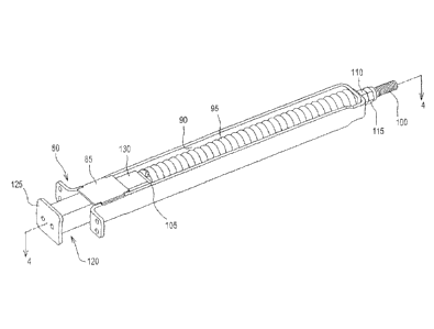
A pivot limiting device for an agricultural implement is disclosed. The agricultural implement includes a first frame section pivotally coupled to a second frame section at a pivot location. The device includes a compression structure having a spring compressed to a preset load. The compression structure is coupled to the first frame section. A plunger includes a first portion positioned adjacent the second frame section and a second portion positioned adjacent the compression structure to move relative thereto between a first position placing no additional compression on the spring when the second frame section pivots in a first direction and contacts the plunger with a first force less than or equal to the preset load, and a second position further compressing the spring when the second frame section pivots in the first direction and contacts the plunger with a second force greater than the preset load.


French Abstract

Un dispositif de limitation de pivotement pour un outil agricole est décrit. Loutil agricole comprend une première section de cadre couplée de manière pivotante à une deuxième section de cadre à un emplacement de pivotement. Le dispositif comprend une structure de compression comportant un ressort comprimé à une charge prédéterminée. La structure de compression est couplée à la première section de cadre. Un piston comprend une première partie positionnée à proximité de la deuxième section de cadre et une deuxième partie positionnée à proximité de la structure de compression afin de se déplacer par rapport à celle-ci entre une première position nexerçant aucune compression supplémentaire sur le ressort lorsque la deuxième section de cadre pivote dans une première direction et vient en contact avec le piston avec une première force inférieure ou égale à la charge prédéterminée, et une deuxième position comprimant davantage le ressort lorsque la deuxième section de cadre pivote dans la première direction et entre en contact avec le piston avec une deuxième force plus importante que la charge prédéterminée.

Claims

Note: Claims are shown in the official language in which they were submitted.


CLAIMS:

1. A pivot limiting device for an agricultural implement, the agricultural
implement
including a first frame section, a second frame section pivotally coupled to
the first frame
section at a pivot location, a first ground-engaging tool coupled to the first
frame section, and
a second ground-engaging tool coupled to the second frame section, the pivot
limiting device
comprising:
a compression structure comprising a spring compressed to a preset load, the
compression structure coupled to the first frame section; and
a plunger comprising a first portion positioned adjacent the second frame
section and
a second portion positioned adjacent the compression structure to move
relative thereto
between a first position placing no additional compression on the spring when
the second
frame section pivots in a first direction at the pivot location and contacts
the first portion of
the plunger with a first force that is less than or equal to the preset load,
and a second
position placing the spring under further compression and thereby limiting
pivotal movement
of the second frame section relative to the first frame section when the
second frame section
pivots in the first direction at the pivot location and contacts the first
portion of the plunger
with a second force that is greater than the preset load.
2. The pivot limiting device of claim 1, wherein the second frame section
is not under
load from the pivot limiting device when the first frame section and the
second frame section
are axially aligned.
3. The pivot limiting device of claim 1, further comprising a hinge at the
pivot location
configured to allow the second frame section to pivot relative to the first
frame section in a
second direction, opposite of the first direction, with no load from the pivot
limiting device.
4. The pivot limiting device of claim 1, wherein the first ground-engaging
tool is a first
disk gang assembly and the second ground-engaging tool is a second disk gang
assembly.
5. The pivot limiting device of claim 1, wherein the compression structure
is coupled to
the second frame section, the first portion of the plunger is positioned

8


adjacent the first frame section, and the second portion of the plunger moves
relative to the
compression structure between the first position placing no additional
compression on the
spring when the first frame section pivots in the first direction at the pivot
location and
contacts the first portion of the plunger with the first force that is less
than or equal to the
preset load, and the second position placing the spring under further
compression and
thereby limiting pivotal movement of the first frame section relative to the
second frame
section when the first frame section pivots in the first direction at the
pivot location and
contacts the first portion of the plunger with the second force that is
greater than the preset
load.
6. The pivot limiting device of claim 1, wherein the pivot limiting device
stops pivotal
movement of second frame section relative to the first frame section when the
spring is
compressed by the plunger creating a spring force that is equal to or greater
than the second
force.
7. The pivot limiting device of claim 1, wherein the compression structure
further
comprises a housing comprising an interior portion containing the spring, a
threaded shaft
passing from exterior of the housing, into the interior portion, and through
the spring, a first
fastener threadably engaged with the threaded shaft in the interior portion
and securing the
spring in the interior portion, and a second fastener threadably engaged with
the threaded
shaft exterior of the housing and operable to compress the spring to the
preset load.
8. The pivot limiting device of claim 7, wherein the second portion of the
plunger is
positioned adjacent the first fastener.
9. An agricultural implement comprising:
a coupling mechanism for coupling to a vehicle;
a first frame section coupled to the coupling mechanism and extending from the

coupling mechanism and adapted to be pulled by the vehicle in a direction of
travel;
a second frame section pivotally coupled to the first frame section at a pivot
location;
a plurality of wheel assemblies coupled to the first frame section and the
second frame
section, the wheel assemblies supporting the first frame section and the
second frame
section above a surface;

9


a first ground-engaging tool coupled to the first frame section;
a second ground-engaging tool coupled to the second frame section; and
a pivot limiting device comprising a compression structure comprising a spring

compressed to a preset load, the compression structure coupled to the first
frame section,
and a plunger comprising a first portion positioned adjacent the second frame
section and a
second portion positioned adjacent the compression structure to move relative
thereto
between a first position placing no additional compression on the spring when
the second
frame section pivots in a first direction at the pivot location and contacts
the first portion of
the plunger with a first force less than or equal to the preset load, and a
second position
placing the spring under further compression and thereby limiting pivotal
movement of the
second frame section relative to the first frame section when the second frame
section pivots
in the first direction at the pivot location and contacts the first portion of
the plunger with a
second force greater than the preset load.
10. The agricultural implement of claim 9, wherein the second frame section
is not under
load from the pivot limiting device when the first frame section and the
second frame section
are axially aligned.
11. The agricultural implement of claim 9, further comprising a hinge at
the pivot location
configured to allow the second frame section to pivot relative to the first
frame section in a
second direction, opposite of the first direction, with no load from the pivot
limiting device.
12. The agricultural implement of claim 9, wherein the first ground-
engaging tool is a first
disk gang assembly and the second ground-engaging tool is a second disk gang
assembly.
13. The agricultural implement of claim 9, wherein the compression
structure is coupled
to the second frame section, the first portion of the plunger is positioned
adjacent the first
frame section, and the second portion of the plunger moves relative to the
compression
structure between the first position placing no additional compression on the
spring when the
first frame section pivots in the first direction at the pivot location and
contacts the first portion
of the plunger with the first force that is less than or equal to the preset
load, and the second
position placing the spring under further compression and thereby limiting
pivotal movement
of the first frame section relative to the second frame section when the first
frame section


pivots in the first direction at the pivot location and contacts the first
portion of the plunger
with the second force that is greater than the preset load.
14. The agricultural implement of claim 9, wherein the pivot limiting
device stops pivotal
movement of second frame section relative to the first frame section when the
spring is
compressed by the plunger creating a spring force that is equal to or greater
than the second
force.
15. The agricultural implement of claim 9, wherein the compression
structure further
comprises a housing comprising an interior portion containing the spring, a
threaded shaft
passing from exterior of the housing, into the interior portion, and through
the spring, a first
fastener threadably engaged with the threaded shaft in the interior portion
and securing the
spring in the interior portion, and a second fastener threadably engaged with
the threaded
shaft exterior of the housing and operable to compress the spring to the
preset load.
16. The agricultural implement of claim 15, wherein the second portion of
the plunger is
positioned adjacent the first fastener.
17. A method of limiting pivotal movement of an agricultural implement, the
agricultural
implement comprising a first frame section, a second frame section pivotally
coupled to the
first frame section at a pivot location, a first ground-engaging tool coupled
to the first frame
section, and a second ground-engaging tool coupled to the second frame
section, the
method comprising:
providing a compression structure comprising a spring compressed to a preset
load,
the compression structure coupled to the first frame section;
providing a plunger comprising a first portion positioned adjacent the second
frame
section and a second portion positioned adjacent the compression structure
moving the plunger relative to the compression structure between a first
position
placing no additional compression on the spring when the second frame section
pivots in a
first direction at the pivot location and contacts the first portion of the
plunger with a first force
that is less than or equal to the preset load; and
moving the plunger relative to the compression structure to a second position
placing
the spring under further compression and thereby limiting pivotal movement of
the second

11


frame section relative to the first frame section when the second frame
section pivots in the
first direction at the pivot location and contacts the first portion of the
plunger with a second
force that is greater than the preset load.
18. The method of claim 17, wherein the second frame section is not under
load from the
compression structure when the first frame section and the second frame
section are axially
aligned.
19. The method of claim 17, further comprising a hinge at the pivot
location configured to
allow the second frame section to pivot relative to the first frame section in
a second
direction, opposite of the first direction, with no load from the compression
structure.
20. The method of claim 17, wherein the compression structure is coupled to
the second
frame section, the first portion of the plunger is positioned adjacent the
first frame section,
and the second portion of the plunger moves relative to the compression
structure between
the first position placing no additional compression on the spring when the
first frame section
pivots in the first direction at the pivot location and contacts the first
portion of the plunger
with the first force that is less.

12

Description

Note: Descriptions are shown in the official language in which they were submitted.


CA 02800457 2013-01-03
FRAME SECTION PIVOT LIMITED DEVICE
Field of the Disclosure
[0001] The present disclosure generally relates to agricultural implements,
and
more particularly to a pivot limiting device of a frame section of
agricultural
implements.
Background of the Disclosure
[0002] In order to provide a wider working width and yet an acceptable
transport
width, agricultural implements commonly include a plurality of foldable frame
sections. The foldable frame sections are pivotally coupled to one another at
a pivot
location so that the agricultural implement can more closely follow the
contour of the
ground and yet fold for transport. The frame sections support a plurality of
ground-
engaging tools (e.g., disk gang assemblies), which are drawn through the soil.
[0003] As the ground-engaging tools are drawn through the soil, forces are
applied to the ground-engaging tools in a rearward, an upward, and an inward
direction. These forces are often referred to as draft force, penetration
force, and
thrust force, respectively. Since the thrust force is applied below the pivot
location,
there is a moment or twist load applied at the pivot location. The twist load
can
cause each frame section to drive deep into the soil on one end while driving
shallow
at the other end. This non-uniform depth across a frame section can create
streaks
in a field, uneven seed bed preparation, and uneven volunteer vegetation
growth.
[0004] Often, the hinge axis is lowered or weight is added to the frame
sections
near the pivot location to create a more uniform depth. Alternatively, the
frame
sections are locked together at the pivot location. A hydraulic system for
controlling
weight transfer between the frame sections is illustrated in commonly assigned
U.S.
Patent No. 4,630,526.
Summary of the Disclosure
[0005] In one embodiment, a pivot limiting device for an agricultural
implement is
disclosed. The agricultural implement includes a first frame section. A second
frame
section is pivotally coupled to the first frame section at a pivot location. A
first
ground-engaging tool is coupled to the first frame section. A second ground-
engaging tool is coupled to the second frame section.
1

CA 02800457 2013-01-03
[0006] The pivot limiting device includes a compression structure having a
spring
compressed to a preset load. The compression structure is coupled to the first
frame
section. Alternatively, the compression structure may be coupled to the second

frame section. A plunger including a first portion is positioned adjacent the
second
frame section. Alternatively, the first portion of the plunger may be
positioned
adjacent the first frame section. The plunger includes a second portion
positioned
adjacent the compression structure to move relative thereto between a first
position
placing no additional compression on the spring when the second frame section
pivots in a first direction at the pivot location and contacts the first
portion of the
plunger with a first force less than or equal to the preset load.
Alternatively, the first
frame section may pivot in the first direction at the pivot location and
contact the first
portion of the plunger. The second portion moves to a second position placing
the
spring under further compression and thereby limiting pivotal movement of the
second frame section relative to the first frame section when the second frame

section pivots in the first direction at the pivot location and contacts the
first portion of
the plunger with a second force greater than the preset load. Alternatively,
pivotal
movement of the first frame section relative to the second frame section may
be
limited when the first frame section pivots in the first direction at the
pivot location
and contacts the first portion of the plunger.
[0007] The second frame section is not under load from the pivot limiting
device
when the first frame section and the second frame section are axially aligned.

Alternatively, the first frame section is not under load from the pivot
limiting device
when the first frame section and the second frame section are axially aligned.
The
pivot limiting device may include a hinge at the pivot location configured to
allow the
second frame section to pivot relative to the first frame section in a second
direction,
opposite of the first direction, with no load from the pivot limiting device.
Alternatively, the hinge may be configured to allow the first frame section to
pivot
relative to the second frame section,
[0008] The first ground-engaging tool may be a first disk gang assembly and
the
second ground-engaging tool may be a second disk gang assembly. The pivot
limiting device may stop pivotal movement of the second frame section relative
to the
2

CA 02800457 2013-01-03
first frame section when the spring is compressed by the plunger creating a
spring
force that is equal to or greater than the second force. Alternatively, the
pivot limiting
device may stop pivotal movement of the first frame section relative to the
second
frame section when the spring is compressed by the plunger creating a spring
force
that is equal to or greater than the second force.
[0009] The compression structure may further include a housing having an
interior portion containing the spring. A threaded shaft may pass from
exterior of the
housing, into the inner portion, and through the spring. A first fastener may
be
threadably engaged with the threaded shaft in the interior portion and secure
the
spring in the interior portion. A second fastener may be threadably engaged
with the
threaded shaft exterior of the housing and operable to compress the spring to
the
preset load. The second portion of the plunger may be positioned adjacent the
first
fastener. It is contemplated by this disclosure that the pivot limiting device
may be
an add-on device that is retrofitted to existing agricultural implements.
[00010] In another embodiment, an agricultural implement is disclosed. The
agricultural implement includes a coupling mechanism for coupling to a
vehicle. A
first frame section is coupled to the coupling mechanism and extends from the
coupling mechanism. The first frame section is adapted to be pulled by the
vehicle
in a direction of travel. A second frame section is pivotally coupled to the
first frame
section at a pivot location. A plurality of wheel assemblies is coupled to the
first
frame section and the second frame section. The wheel assemblies support the
first
frame section and the second frame section above a surface. A first ground-
engaging tool is coupled to the first frame section. A second ground-engaging
tool is
coupled to the second frame section. The agricultural implement includes a
pivot
limiting device as described in the embodiment above.
[00011] In yet another embodiment, a method of limiting pivotal movement of an

agricultural implement is disclosed. The agricultural implement includes a
first frame
section and a second frame section pivotally coupled to the first frame
section at a
pivot location. A first ground-engaging tool is coupled to the first frame
section. A
second ground-engaging tool is coupled to the second frame section. The method

includes providing a compression structure including a spring compressed to a
3

CA 02800457 2013-01-03
preset load. The compression structure is coupled to the first frame section.
Alternatively, the compression structure may be coupled to the second frame
section. The method includes providing a plunger including a first portion
positioned
adjacent the second frame section and a second portion positioned adjacent the

compression structure. Alternatively, the first portion of the plunger may be
positioned adjacent the first frame section. The method includes moving the
plunger
relative to the compression structure between a first position placing no
additional
compression on the spring when the second frame section pivots in a first
direction
at the pivot location and contacts the first portion of the plunger with a
first force that
is less than or equal to the preset load. Alternatively, the first frame
section may
pivot in the first direction at the pivot location and contact the first
portion of the
plunger. The method includes moving the plunger relative to the compression
structure to a second position placing the spring under further compression
and
thereby limiting pivotal movement of the second frame section relative to the
first
frame section when the second frame section pivots in the first direction at
the pivot
location and contacts the first portion of the plunger with a second force
that is
greater than the preset load. Alternatively, pivotal movement of the first
frame
section relative to the second frame section may be limited when the first
frame
section pivots in the first direction at the pivot location and contacts the
first portion of
the plunger.
Brief Description of the Drawings
[00012] FIG. 1 is a perspective view of an agricultural implement according to
one
embodiment showing a pivot limiting device.
[00013] FIG. 2 is an enlarged perspective view of a portion of the
agricultural
implement of FIG. 1.
[00014] FIG. 3 is an enlarged perspective view of the pivot limiting device of
the
agricultural implement of FIG. 1.
[00015] FIG. 4 is a sectional view taken along lines 4-4 of FIG. 3.
[00016] Before any embodiments are explained in detail, it is to be understood
that
the disclosure is not limited in its application to the details of
construction and the
4

CA 02800457 2013-01-03
arrangement of components set forth in the following description or
illustrated in the
following drawings. The disclosure is capable of other embodiments and of
being
practiced or of being carried out in various ways.
Detailed Description
[00017] FIG. 1 illustrates an agricultural implement 10 according to one
embodiment. The illustrated agricultural implement 10 includes a coupling
mechanism 15 for coupling to a vehicle (not shown).
[00018] A first frame section 20 is coupled to the coupling mechanism 15. The
first
frame section 20 extends rearwardly from the coupling mechanism 15 in a
direction
opposite of a direction of travel 25. A second frame section 30 is pivotally
coupled to
the first frame section 20 at a pivot location 35. The illustrated pivot
location 35 is a
hinge 40. A plurality of wheel assemblies 45 are coupled to the first and
second
frame sections 20, 30. The wheel assemblies 45 support the first and second
frame
sections 20, 30 above a surface 50.
[00019] A first ground-engaging tool 55 is coupled to the first frame section
20.
The illustrated first ground-engaging tool 55 is a first disk gang assembly
60. A
second ground-engaging tool 65 is coupled to the second frame section 30. The
illustrated second ground-engaging tool 65 is a second disk gang assembly 70.
[00020] FIGS. 1 ¨4 illustrate a pivot limiting device 75, which is direct-
acting and
not remote from the pivot location 35. Although the illustrated agricultural
implement
depicts four pivot limiting devices 75, less than four and more than four
pivot
limiting devices 75 are contemplated by this disclosure. Referring to FIG. 2,
the pivot
limiting device 75 includes a compression structure 80 that is coupled to the
first
frame section 20 with a plurality of fasteners 82. Referring to FIGS. 3 and 4,
the
compression structure 80 includes a housing 85 having an interior portion 90
containing a spring 95. A threaded shaft 100 passes from exterior of the
housing 85
into the interior portion 90 and through the spring 95. A first fastener 105
is
threadably engaged with the threaded shaft 100 in the interior portion 90 and
secures the spring 95 in the interior portion 90. A second fastener 110 is
threadably
engaged with the threaded shaft 100 exterior of the housing 85. A jam nut 115
5

CA 02800457 2013-01-03
secures the second fastener 110.
[00021] A plunger 120 includes a first portion 125 positioned adjacent the
second
frame section 30. The plunger 120 includes a second portion 130 positioned
adjacent the first fastener 105 in the compression structure 80.
[00022] In operation, the coupling mechanism 15 is adapted to be pulled by the

vehicle in the direction of travel 25. As illustrated in FIG. 1, on level
ground, the first
frame section 20 is axially aligned with the second frame section 30 such that
the
pivot limiting device 75 applies no load to the second frame section 30. The
second
fastener 110 is operable to compress the spring 95 to a preset load and the
second
portion 130 of the plunger 120 is positioned to move relative to the
compression
structure 80 between a first position placing no additional compression on the
spring
95 when the second frame section 30 pivots in a first direction 135 at the
pivot
location 35 and contacts the first portion 125 of the plunger 120 with a first
force that
is less than or equal to the preset load. The second portion 130 of the
plunger 120 is
also positioned to move relative to the compression structure 80 to a second
position
placing the spring 95 under further compression and thereby limiting pivotal
movement of the second frame section 30 relative to the first frame section 20
when
the second frame section 30 pivots in the first direction 135 at the pivot
location 35
and contacts the first portion 125 of the plunger 120 with a second force that
is
greater than the preset load.
[00023] Therefore, once the thrust force causes the second frame section 30 to

pivot relative to the first frame section 20 in the first direction 135, the
spring 95
begins to apply the preset load. Once the preset load is completely applied,
the
plunger 120 slides and compresses the spring 95 further and applies a spring
force
equivalent to a linear spring rate plus the preset load. No outside controls
are
required to activate the pivot limiting device 75.
[00024] The pivot limiting device 75 is operable to stop pivotal movement of
the
second frame section 30 relative to the first frame section 20 when the spring
95 is
compressed by the plunger 120 creating the spring force that is equal to or
greater
than the second force. Alternatively, the pivot limiting device 75 is operable
to stop
pivotal movement of the first frame section 20 relative to the second frame
section
6

CA 02800457 2013-01-03
30.
[00026] While the disclosure has been illustrated and described in detail in
the
drawings and foregoing description, such illustration and description is to be

considered as exemplary and not restrictive in character, it being understood
that
illustrative embodiments have been shown and described and that all changes
and
modifications that come within the spirit of the disclosure are desired to be
protected.
It will be noted that alternative embodiments of the present disclosure may
not
include all of the features described yet still benefit from at least some of
the
advantages of such features. Those of ordinary skill in the art may readily
devise
their own implementations that incorporate one or more of the features of the
present
disclosure and fall within the spirit and scope of the present invention as
defined by
the appended claims.
[00026] Various features are set forth in the following claims.
7

Representative Drawing
A single figure which represents the drawing illustrating the invention.
Administrative Status

For a clearer understanding of the status of the application/patent presented on this page, the site Disclaimer , as well as the definitions for Patent , Administrative Status , Maintenance Fee  and Payment History  should be consulted.

Administrative Status

Title Date
Forecasted Issue Date 2019-04-23
(22) Filed 2013-01-03
(41) Open to Public Inspection 2013-07-17
Examination Requested 2017-12-04
(45) Issued 2019-04-23

Abandonment History

There is no abandonment history.

Maintenance Fee

Last Payment of $263.14 was received on 2023-12-29


 Upcoming maintenance fee amounts

Description Date Amount
Next Payment if small entity fee 2025-01-03 $125.00
Next Payment if standard fee 2025-01-03 $347.00

Note : If the full payment has not been received on or before the date indicated, a further fee may be required which may be one of the following

  • the reinstatement fee;
  • the late payment fee; or
  • additional fee to reverse deemed expiry.

Patent fees are adjusted on the 1st of January every year. The amounts above are the current amounts if received by December 31 of the current year.
Please refer to the CIPO Patent Fees web page to see all current fee amounts.

Payment History

Fee Type Anniversary Year Due Date Amount Paid Paid Date
Application Fee $400.00 2013-01-03
Maintenance Fee - Application - New Act 2 2015-01-05 $100.00 2014-12-19
Maintenance Fee - Application - New Act 3 2016-01-04 $100.00 2015-12-18
Maintenance Fee - Application - New Act 4 2017-01-03 $100.00 2016-12-20
Request for Examination $800.00 2017-12-04
Maintenance Fee - Application - New Act 5 2018-01-03 $200.00 2017-12-19
Maintenance Fee - Application - New Act 6 2019-01-03 $200.00 2018-12-18
Final Fee $300.00 2019-03-05
Maintenance Fee - Patent - New Act 7 2020-01-03 $200.00 2019-12-27
Maintenance Fee - Patent - New Act 8 2021-01-04 $200.00 2020-12-28
Maintenance Fee - Patent - New Act 9 2022-01-04 $204.00 2021-12-27
Maintenance Fee - Patent - New Act 10 2023-01-03 $254.49 2022-12-30
Maintenance Fee - Patent - New Act 11 2024-01-03 $263.14 2023-12-29
Owners on Record

Note: Records showing the ownership history in alphabetical order.

Current Owners on Record
DEERE & COMPANY
Past Owners on Record
None
Past Owners that do not appear in the "Owners on Record" listing will appear in other documentation within the application.
Documents

To view selected files, please enter reCAPTCHA code :


To view images, click a link in the Document Description column. To download the documents, select one or more checkboxes in the first column and then click the "Download Selected in PDF format (Zip Archive)" or the "Download Selected as Single PDF" button.

List of published and non-published patent-specific documents on the CPD .

If you have any difficulty accessing content, you can call the Client Service Centre at 1-866-997-1936 or send them an e-mail at CIPO Client Service Centre.


Document
Description 
Date
(yyyy-mm-dd) 
Number of pages   Size of Image (KB) 
Abstract 2013-01-03 1 23
Description 2013-01-03 7 362
Claims 2013-01-03 5 238
Drawings 2013-01-03 3 125
Cover Page 2013-07-22 2 93
Representative Drawing 2013-07-23 1 55
Request for Examination 2017-12-04 1 28
Examiner Requisition 2018-09-04 3 176
Amendment 2018-10-01 6 266
Claims 2018-10-01 5 225
Final Fee 2019-03-05 2 43
Representative Drawing 2019-03-25 1 9
Cover Page 2019-03-25 1 41
Assignment 2013-01-03 3 83