Note: Descriptions are shown in the official language in which they were submitted.
CA 2800627 2017-05-16
PERFORMANCE-ENHANCING WINGLET SYSTEM AND METHOD
FIELD
The present disclosure relates generally to aerodynamics and, more
particularly, to wing tip
devices such as for the wings of an aircraft.
BACKGROUND
Induced drag is generated by an aircraft wing due to the redirection of air
during the generation
of lift as the wing moves through the air. The redirection of the air may
include spanwise flow
along the underside of the wing along a generally outboard direction toward
the wing tips where
the air then flows upwardly over the wing tips. The air flowing over the tips
joins a chordwise
flow of air over the wing resulting in the formation of wing tip vortices. The
wing tip vortices
are fed by other vortices that are shed by the trailing edge of the wing. The
downwash of
vortices trailing from the wing reduces the effective angle of attack of the
wing which results in
a reduction in generated lift.
Winglets provide a means for reducing the negative effects of induced drag
such as by
effectively increasing the length of the trailing edge of the wing. The
effective increase in the
length of the trailing edge may spread out the distribution of the vortices
which may reduce
losses from induced drag. In this regard, winglets may provide a significant
reduction in
induced drag which may improve the performance of the aircraft. Furthermore,
winglets may
provide an increase in effective trailing edge length without increasing the
length of the wing
leading edge. Additionally, by adding winglets to the wings instead of
increasing the wing span
in the conventional manner by extending the wing tips, the added weight, cost,
and complexity
associated with lengthening of leading edge lift-enhancement devices (e.g.,
slats, Krueger flaps)
may be avoided.
However, conventional winglets may increase the aerodynamic loading at the
wing tips which
may result in an increase in wing bending under high lift conditions. The
increase in wing
bending may require strengthening or stiffening of the wing structure which
adds weight and
which may negate the drag-reducing benefits provided by the winglets. In
addition, the center of
gravity of conventional winglets may be located at a relatively long distance
from the torsional
axis of the wing which may affect the flutter characteristics of the wing. In
an attempt to
-1-
CA 2800627 2017-05-16
counteract the inertial effects of conventional winglets, ballast may be added
to the leading edge
of the wing tip. Unfortunately, the addition of ballast may negate some of the
drag-reducing
benefits provided by the winglet. Conventional winglets may also suffer
reduced aerodynamic
efficiency due to flow separation that may occur at high loading conditions
including at low
speeds.
As can be seen, there exists a need in the art for a wing tip device that may
reduce the induced
drag of a wing without increasing wing bending. In addition, there exists a
need in the art for a
wing tip device which minimizes the impact on flutter characteristics of the
wing. Furthermore,
there exists a need in the art for a wing tip device that does not require the
addition of ballast to
overcome the inertial effects of a winglet on the flutter characteristics of
the wing.
SUMMARY
Any one or more of the above-noted needs associated with conventional winglets
may be
specifically addressed and alleviated by the present disclosure which provides
a winglet system
for an aircraft wing wherein the winglet system includes an upper winglet and
a lower winglet
mounted to a wing tip. The lower winglet may have a static position when the
wing is subjected
to a ground static loading. The lower winglet may be configured such that
upward deflection of
the wing under an approximate 1-g flight loading causes the lower winglet to
move from the
static position to an in-flight position and resulting in a relative span
increase of the wing.
Also disclosed is an aircraft having a pair of wings with each wing having a
wing tip. The
aircraft may include an upper winglet and a lower winglet mounted to each one
of the wing tips.
The lower winglets may be sized and oriented such that upward deflection of
the wings under an
approximate 1-g flight loading results in a relative span increase of the
wings.
In a further embodiment, disclosed is a method of enhancing the performance of
an aircraft
including the step of providing an upper winglet and a lower winglet on a
wing. The lower
winglet may have a static position when the wing is subject to a ground static
loading. The
method may further include upwardly deflecting the wing under an approximate 1-
g flight
loading. In addition, the method may include moving the lower winglet from the
static position
to an in-flight position during upward deflection of the wing. The method may
also include
causing a relative span increase of the wing when moving the lower winglet
from the static
position to the in-flight position.
-2-
CA 02800627 2013-01-07
A winglet system may comprise an upper winglet and a lower winglet mounted to
a wing;
the lower winglet having a static position when the wing is subject to a
ground static loading;
and the lower winglet being configured such that upward deflection of the wing
under an
approximate 1-g flight loading causes the lower winglet to move from the
static position to an
in-flight position and resulting in a relative span increase of the wing. The
winglet system
may include a lower winglet that is oriented at an anhedral angle of no less
than
approximately 15 degrees during upward deflection of the wing under the
approximate 1-g
flight loading.
The upper winglet may be oriented at a dihedral angle of at least
approximately 60 degrees
during upward deflection of the wing under the approximate 1-g flight loading.
The winglet system may include a the lower winglet that has a center of
pressure;the wing
having a wing torsional axis; and the center of pressure of the lower winglet
being located aft
of the wing torsional axis. The winglet system may include a wing that has a
wing tip
including a wing tip chord; the upper winglet and the lower winglet each
having a root chord;
and the upper winglet root chord and the lower winglet root chord each having
a length of at
least approximately 50 percent of the wing tip chord. The upper winglet root
chord and the
lower winglet root chord each may have a length of from approximately 60 to
100 percent of
a length of the wing tip chord.
The winglet system may have at at least one of the upper winglet and lower
winglet that has a
leading edge root glove mounted at a juncture of a wing tip with the
respective upper winglet
and lower winglet. The lower winglet may have a length of at least
approximately 50 percent
of a length of the upper winglet. The upper winglet and the lower winglet may
have a taper
ratio of tip chord to root chord in a range of from approximately 0.15 to
0.50. The upper
winglet and the lower winglet can have a leading edge sweep angle of between
approximately
20 and 70 degrees.
The wing may have a wing torsional axis; the upper winglet and the lower
winglet having a
combined winglet area and a combined center of gravity located at a
longitudinal offset from
the wing torsional axis; and the upper winglet and lower winglet being
configured such that
the longitudinal offset is less than a longitudinal offset of a center of
gravity of a single upper
-3-
CA 02800627 2013-01-07
winglet having a winglet area that is substantially equivalent to the combined
winglet area
and having a leading edge sweep angle that is substantially equivalent to the
upper winglet
leading edge sweep angle.
An embodiment of the invention involves an aircraft comprising a pair of wings
each having
a wing tip; and an upper winglet and a lower winglet mounted to each one of
the wing tips;
the lower winglets being sized and oriented such that upward deflection of the
wings under
an approximate 1-g flight loading results in a relative span increase of the
wing.
A method of enhancing performance of an aircraft can comprise the steps of:
providing an
upper winglet and a lower winglet on a wing, the lower winglet having a static
position when
the wing is subject to a ground static loading; upwardly deflecting the wing
under an
approximate 1-g flight loading; moving the lower winglet from the static
position to an in-
flight position during upward deflection of the wing; and causing a relative
span increase of
.. the wing when moving the lower winglet from the static position to the in-
flight position.
The method may also comprise the steps of: deflecting the lower winglet
upwardly during the
approximate 1-g flight loading; and increasing an effective wing span during
upward
deflection of the lower winglet.
To further enhance performance, the method may comprise the step of orienting
the lower
winglet at an anhedral angle of no less than approximately 15 degrees during
the upward
deflection of the wing. The method may further comprise the step of: orienting
the upper
winglet at a dihedral angle of at least approximately 60 degrees during the
upward deflection
of the wing. To enhance aerodynamics, the method can further comprise the
steps of
locating the lower winglet such that a center of pressure is aft of a wing
torsional axis;
increasing lift of the lower winglet during a gust load; and exerting a nose-
down moment on a
wing tip in response to an increase in the lift of the lower winglet. To
increase efficiency,
the method can further comprise the step of dividing a wing tip aerodynamic
load between
the upper winglet and the lower winglet, the upper winglet and the lower
winglet each having
.. a root chord having a length of at least approximately 50 percent of a wing
tip chord. To
improve performance, the method may further comprising the step of minimizing
parasitic
drag of the aircraft by using a leading edge root glove on at least one of the
upper winglet and
the lower winglet. To enhance aerodynamics, the method may further comprising
the steps
of providing the upper winglet and the lower winglet with a combined winglet
area and a
-4-
combined center of gravity that is longitudinally offset from a wing torsional
axis; and
reducing wing flutter by longitudinally offsetting the combined center of
gravity by an
amount that is less than a longitudinal offset of a center of gravity of a
single upper winglet
having a winglet area that is substantially equivalent to the combined winglet
area and having
a leading edge sweep angle that is substantially equivalent to the upper
winglet leading edge
sweep angle.
A winglet system, comprising: an upper winglet and a lower winglet mounted to
a
wing, the lower winglet having a length of between approximately 50 to
approximately 80
percent of a length of the upper winglet; the lower winglet having a static
position when the
wing is subject to an on-ground static loading; and the lower winglet being
configured such
that upward deflection of the wing under an approximate 1-g flight loading
causes the lower
winglet to move upwardly and outwardly from the static position to an in-
flight position
resulting in a span increase of the wing under the approximate 1-g flight
loading relative to
the span of the wing under the on-ground static loading.
An aircraft, comprising: a pair of wings each having a wing tip; an upper
winglet and
a lower winglet mounted to each one of the wing tips, each lower winglet
having a length of
between approximately 50 to approximately 80 percent of a length of a
respective upper
winglet; each lower winglet having a static position when a respective wing is
subject to an
on-ground static loading; and each lower winglet being sized and oriented such
that upward
.. deflection of the respective wing under an approximate 1-g flight loading
causes the lower
winglet to move upwardly and outwardly from the static position to an in-
flight position
resulting in a span increase of the respective wing under the approximate 1-g
flight loading
relative to the span of the respective wing under an on-ground static loading.
A method of enhancing performance of an aircraft, comprising the steps of:
providing
an upper winglet and a lower winglet on a wing, the lower winglet having a
static position
when the wing is subject to a ground static loading, the lower winglet having
a length of
between approximately 50 to approximately 80 percent of a length of the upper
winglet;
upwardly deflecting the wing under an approximate 1-g flight loading; moving
the lower
winglet upwardly and outwardly from the static position to an in-flight
position during
upward deflection of the wing; and causing a span increase of the wing under
the
approximate 1-g flight loading relative to the span of the wing under the on-
ground static
loading in response to moving the lower winglet from the static position to
the in-flight
position.
5
CA 2800627 2019-01-11 - -
CA 2800627 2017-05-16
A winglet system, may comprise: an upper winglet and a lower winglet each
having a
root chord and being mounted to a wing tip of a wing, the wing tip having a
wing tip chord;
the upper winglet root chord and the lower winglet root chord each having a
length of no
greater than 100 percent of the wing tip chord; the lower winglet having a
static position
when the wing is subject to an on-ground static loading; and the lower winglet
being
configured such that upward deflection of the wing under an approximate 1-g
flight loading
causes the lower winglet to move upwardly and outwardly from the static
position to an in-
flight position resulting in an effective span increase of the wing under the
approximate 1-g
flight loading relative to the span of the wing under the on-ground static
loading.
An aircraft, may comprise: a pair of wings each having a wing tip including a
wing tip
chord; an upper winglet and a lower winglet mounted to each one of the wing
tips, each upper
winglet and each lower winglet having a root chord; each upper winglet root
chord and each
lower winglet root chord having a length of no greater than 100 percent of a
respective wing
tip chord; each lower winglet having a static position when a respective wing
is subject to an
on-ground static loading; and each lower winglet being sized and oriented such
that upward
deflection of the respective wing under an approximate 1-g flight loading
causes the lower
winglet to move upwardly and outwardly from the static position to an in-
flight position
resulting in an effective span increase of the respective wing under the
approximate 1-g flight
loading relative to the span of the respective wing under an on-ground static
loading.
A method of enhancing performance of an aircraft, may comprise the steps of:
providing an upper winglet and a lower winglet on a wing tip of a wing, the
wing tip having a
wing tip chord, the lower winglet having a static position when the wing is
subject to an on-
ground static loading, the upper winglet and the lower winglet each having a
root chord
having a length of no greater than 100 percent of the wing tip chord; upwardly
deflecting the
wing under an approximate 1-g flight loading; moving the lower winglet
upwardly and
outwardly from the static position to an in-flight position during upward
deflection of the
wing; and causing an effective span increase of the wing under the approximate
1-g flight
loading relative to the span of the wing under the on-ground static loading in
response to
moving the lower winglet upwardly and outwardly from the static position to
the in-flight
position.
- 5a -
CA 2800627 2017-05-16
A winglet system, may comprise: an upper winglet and a lower winglet mounted
to a
wing; the lower winglet having a static position when the wing is subject to
an on-ground
static loading, the lower winglet being substantially straight in the static
position; and the
lower winglet being configured such that upward deflection of the wing under
an
approximate 1-g flight loading causes the lower winglet to move upwardly and
outwardly
from the static position to an in-flight position resulting in an effective
span increase of the
wing under the approximate 1-g flight loading relative to the span of the wing
under the on-
ground static loading.
An aircraft, may comprise: a pair of wings each having a wing tip; an upper
winglet
and a lower winglet mounted to each one of the wing tips; each lower winglet
having a static
position when a respective wing is subject to an on-ground static loading, the
lower winglet
being substantially straight in the static position; and each lower winglet
being configured
such that upward deflection of the respective wing under an approximate 1-g
flight loading
.. causes the lower winglet to move upwardly and outwardly from the static
position to an in-
flight position resulting in an effective span increase of the respective wing
under the
approximate 1-g flight loading relative to the span of the respective wing
under the on-ground
static loading.
A method of enhancing performance of an aircraft, may comprise the steps of:
providing an upper winglet and a lower winglet on a wing tip of a wing, the
lower winglet
having a static position when the wing is subject to an on-ground static
loading, the lower
winglet being substantially straight in the static position; upwardly
deflecting the wing under
an approximate 1-g flight loading; moving the lower winglet upwardly and
outwardly from
the static position to an in-flight position during upward deflection of the
wing; and causing
an effective span increase of the wing under the approximate 1-g flight
loading relative to the
span of the wing under the on-ground static loading in response to moving the
lower winglet
upwardly and outwardly from the static position to the in-flight position.
- 5b -
CA 2800627 2017-05-16
The features, functions and advantages that have been discussed can be
achieved independently in various embodiments of the present disclosure or may
be
combined in yet other embodiments, further details of which can be seen with
reference to the
following description and drawings below.
BRIEF DESCRIPTION OF THE DRAWINGS
These and other features of the present disclosure will become more apparent
upon reference
to the drawings wherein like numbers refer to like parts throughout and
wherein:
Figure 1 is a perspective illustration of an aircraft having a winglet system
mounted on each
wing tip of the wings;
Figure 2 is a front view of the aircraft illustrating an upper winglet and a
lower winglet
included with the winglet system mounted to each wing tip;
Figure 3 is a side view of one of the winglet systems taken along line 3 of
Figure 2 and
illustrating the upper winglet and the lower winglet mounted to a wing tip;
Figure 4 is a top view of the upper winglct taken along line 4 of Figure 3 and
illustrating a
twist angle or washout that may optionally be incorporated into the upper
winglet;
Figure 5 is a top view of the lower winglet taken along line the 5 of Figure 3
and illustrating a
twist angle that may optionally be incorporated into the lower winglet;
Figure 6 is a schematic front view of one of the wings in a jigged shape, in a
downwardly-
deflected ground static loading shape, and in an upwardly-deflected 1-g flight
loading (e.g.,
1-g wing loading) shape;
- 5c -
CA 02800627 2013-01-07
Figure 7 is a schematic view of the relative positions of the upper and lower
winglets for the
wing in the three different shapes illustrated in Figure 6;
Figure 8 is a front view of the aircraft illustrating the lower winglet on
each wing tip being
moved from a static position, wherein the wing is subjected to a ground static
loading, to an
in-flight position, wherein the wing is subjected to the approximate 1-g
flight loading, and
further illustrating an increase in effective wing span occurring in response
to movement of
the lower winglets from the static position to the in-flight position;
Figure 9 is a side view of an embodiment of a single upper winglet having a
center of gravity
located at a longitudinal offset from a torsional axis of the wing;
Figure 10 is a side view of the winglet system disclosed herein wherein the
combination of
the upper and lower winglet results in a combined center of gravity located at
a reduced
longitudinal offset to the torsional axis relative to the greater longitudinal
offset for the single
upper winglet and which advantageously minimizes the inertial effects of the
winglet system
on the flutter of the wing;
Figure 11 is a side view of an alternative embodiment of the winglet system
wherein the
trailing edges of the upper winglet and lower winglet are generally aligned
with the wing
trailing edge;
Figure 12 is a side view of a further embodiment of the winglet system having
leading edge
root gloves mounted at a juncture of the wing tip to each of the upper winglet
and the lower
winglet;
Figure 13 is a perspective view of an embodiment of the winglet system
illustrating a center
of pressure of the lower winglet located aft of the wing torsional axis due to
a relatively large
sweep angle of the lower winglet and due to a relatively small anhedral angle
of the lower
winglet;
-6-
CA 02800627 2013-01-07
Figure 14 is a side view of the winglet system taken along line 14 of Figure
13 and
illustrating a nose-down moment exerted on the wing tip in response to an
increase in lift of
the lower winglet in response to a gust load; and
Figure 15 is a flow diagram having one or more operations that may be included
in a method
of operating an aircraft.
DETAILED DESCRIPTION
Referring now to the drawings wherein the showings are for purposes of
illustrating various
embodiments of the present disclosure, shown in Figure 1 is a perspective view
of an aircraft
10 having a fuselage 12. The fuselage 12 may include a cabin for passengers
and flight crew.
The fuselage 12 may extend from a nose at a forward end 24 of the aircraft 10
to an
empennage 18 at an aft end 26 of the fuselage 12. The empennage 18 may include
one or
more tail surfaces such as a vertical stabilizer 22 and/or a horizontal
stabilizer 20 for control
of the aircraft 10. The aircraft 10 may further include a pair of wings 50,
one or more
propulsion units 16, and nose and main landing gear 14 (Figure 2). The wings
50 may
include one or more winglet systems 98 as disclosed herein. Each winglet
system 98 may
comprise an upper winglet 100 and a lower winglet 200 and which may be mounted
to a wing
tip 56 of a wing 50.
It should be noted that although the winglet system 98 of the present
disclosure is described
in the context of a fixed wing passenger aircraft 10 such as the tube-and-wing
aircraft 10
illustrated in Figure 1, any one of the various winglet system 98 embodiments
may be applied
to any aircraft of any configuration, without limitation. For example, the
winglet system 98
may be applied to any civil, commercial, or military aircraft. In addition,
the embodiments of
the winglet system 98 disclosed herein may he applied to alternative aircraft
configurations
and are not limited to the tube-and-wing aircraft 10 configuration illustrated
in Figure 1. For
example, the disclosed embodiments may be applied to hybrid wing-body aircraft
or blended-
wing aircraft.
The winglet system 98 may also be applied to aerodynamic surfaces or lifting
surfaces other
than wings 50. For example, the winglet system 98 may be applied to a canard,
to a control
surface such as a horizontal stabilizer, or to any other lifting surface where
it is desired to
mitigate the adverse effects of induced drag and/or to enhance aerodynamic
performance.
-7-
CA 02800627 2013-01-07
Advantageously, the upper and lower winglets 100, 200 as disclosed herein may
be provided
in relatively large sizes with relatively long root chords and relatively high
degrees of sweep
and/or taper. The lower winglet 200 is advantageously provided with a
relatively limited
amount of anhedral angle 224 (Figure 8) which results in an increase in
effective wing span
.. 80 (Figure 8) when the wings 50 are aeroelastically deflected upwardly such
as under an
approximate 1-g flight loading 78 (Figure 6) during cruise flight. In
addition, the lower
winglet 200 may also be configured to aeroelastically deflect upwardly under
the
approximate 1-g flight loading 78 and which may result in a relative span
increase 84 (Figure
7) and may contribute toward increasing the effective wing span 80 (Figure 7)
of the wings
50 as illustrated in Figures 6-8 and described in greater detail below.
Advantageously, by
increasing the effective wing span 80 due to the upward deflection of the wing
50 and/or due
to upward deflection of the lower winglet 200, the lift-to-drag performance of
the aircraft 10
may be improved.
In Figure 1, the installation of the winglet system 98 on the aircraft 10 may
be defined with
regard to a coordinate system having a longitudinal axis 28, a lateral axis
30, and a vertical
axis 32. The longitudinal axis 28 may be defined as extending through a
general center of the
fuselage 12 between the forward end 24 and the aft end 26. The lateral axis 30
may be
oriented orthogonally relative to the longitudinal axis 28 and may extend
generally along the
wing 50 outboard directions relative to a center of the fuselage 12. The
vertical axis 32 may
be oriented orthogonally relative to the longitudinal and lateral axes 28, 30.
Each one of the
wings 50 of the aircraft 10 shown in Figure 1 may extend from a wing root 52
having a root
chord 54 to a wing tip 56 having a tip chord 58. Each wing 50 may have upper
and lower
surfaces 64, 66 and may include a wing leading edge 60 and a wing trailing
edge 62. In the
embodiment shown, the wing leading edge 60 may be formed at a wing sweep angle
68.
Each wing 50 may extend upwardly at a dihedral angle 70. However, the wings 50
upon
which the winglet systems 98 may be mounted may be provided in any geometric
configuration and are not limited to the above-described arrangement for the
aircraft 10
shown in Figure 1.
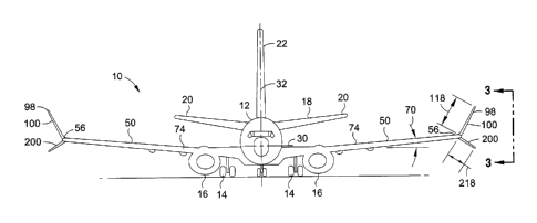
Figure 2 is a front view of the aircraft 10 supported by the landing gear 14
and illustrating a
winglet system 98 mounted to the wing tip 56 of each wing. The wings 50 are
shown in a
jigged shape 74 (Figure 6) wherein the wings 50 are relatively straight as may
occur when the
wings 50 are constrained by assembly tooling during the manufacturing of the
aircraft 10. In
-8-
CA 02800627 2013-01-07
one example, a jigged shaped (e.g., jigged shape 74 ¨ Figure 6) may be defined
as an
equilibrium state (e.g., an unloaded state) of an elastic member (e.g., a wing
50). As
indicated in greater detail below, when the aircraft 10 is supported by the
landing gear 14, the
wings 50 may typically assume a slightly downwardly-deflected shape under a
ground static
loading 76 (Figure 6) due to the gravitational force acting on the mass of the
wings 50, the
propulsion units 16, and/or other systems supported by the wings 50.
Each wing tip 56 may include a winglet system 98 comprising the upper winglet
100 and the
lower winglet 200. The upper winglet 100 may have an upper winglet root 102
which may
be affixed or otherwise coupled to the wing 50 at the wing tip 56. The upper
winglet 100
may extend as a relatively straight member toward the upper winglet tip 106.
Likewise, the
lower winglet 200 may have a lower winglet root 202 which may be affixed to
the wing 50 at
the wing tip 56. In an embodiment, the lower winglet root 202 may intersect or
may be
joined with the upper winglet root 102 at the wing tip 56. The lower winglet
200 may extend
as a relatively straight member toward the lower winglet 206 tip. However, the
upper winglet
100 and/or the lower winglet 200 may be provided in a non-straight shape and
may include
curved shapes or contoured shapes and may further include combinations of
straight shapes,
curved shapes, and contoured shapes.
The upper winglet 100 may have an upper winglet length 118 (e.g., a semi-span)
extending
from the upper winglet root 102 to the upper winglet tip 106. In the
embodiment shown, the
upper winglet length 118 may be longer than a lower winglet length 218 of the
lower winglet
200. In an embodiment, the lower winglet 200 may have a lower winglet length
218 of at
least approximately 50 percent of the upper winglet length 118 of the upper
winglet 100. In a
further embodiment, the lower winglet 200 may have a lower winglet length 218
in the range
of from approximately 50 to 80 percent of the upper winglet length 118 of the
upper winglet
100. In an embodiment of a commercial transport aircraft 10, the upper winglet
100 may be
provided in an upper winglet length 118 of from approximately 50 to 150
inches. For
example, the upper winglet 100 may be provided in an upper winglet length 118
of from 90
to 110 inches. The lower winglet length 218 may extend from the lower winglet
root 202 to
the lower winglet tip 206 and may be provided in a lower winglet length 218 of
from
approximately 30 to 100 inches. For example, the lower winglet 200 may be
provided in a
lower winglet length 218 of from 50 to 70 inches. However, the upper winglet
100 and the
lower winglet 200 may be provided in any length and are not limited to the
length ranges
-9-
CA 02800627 2013-01-07
mentioned above. Furthermore, although not shown, the winglet system 98 may be
provided
in an embodiment wherein the lower winglet 200 is longer than the upper
winglet 100. In
addition, in one or more of embodiments, the lower winglet 100 may be
configured such that
the lower winglet tip 206 is located approximately at the intersection of the
gate span limit 38
(Figure 6) and the roll and pitch clearance line 42 (Figure 6) as described
below.
In Figure 3, shown is a side view of the winglet system 98 mounted to the wing
tip 56 of the
wing 50. The upper winglet root 102 is joined to the wing tip 56 at a wing-
upper winglet
juncture 150. Likewise, the lower winglet root 202 is joined to the wing tip
56 at a wing-
lower winglet juncture 152. Although the illustration shows the upper winglet
root 102 and
lower winglet root 202 being respectively mounted to the upper and lower
portions of a wing
tip 56, the winglet system 98 may be configured such that the upper winglet
100 at least
partially intersects the lower winglet 200 at an upper winglet-lower winglet
juncture 154. In
this regard, the upper winglet root 102 and the lower winglet root 202 may be
mounted to the
wing tip 56 at any vertical location relative to one another. In addition,
although the figures
of the present disclosure show the upper winglet root 102 and the lower
winglet root 202 as
being generally aligned with one another at the juncture of the upper and
lower winglet roots
102, 202 with the wing tip 56, the upper winglet root 102 may be joined to the
wing tip 56
such that the upper winglet root 102 is located forward of the lower winglet
root 202.
.. Alternatively, the lower winglet root 202 may be joined to the wing tip 56
such that the lower
winglet root 202 is located forward of the upper winglet root 102. In this
regard, the upper
winglet root 102 may be joined to the wing tip 56 such that the upper winglet
leading edge
112 is located forward of the lower winglet leading edge 212, or vice versa.
Likewise, the
upper winglet root 102 may be joined to the wing tip such that the upper
winglet trailing edge
112 is located forward of the lower winglet trailing edge 212, or vice versa.
Furthermore, although the present disclosure illustrates the upper winglet
root 102 and the
lower winglet root 202 as being generally aligned with one another in a
lateral direction (e.g.,
along a direction parallel to the lateral axis 30 - Figure 2), the upper
winglet root 102 (Figure
.. 3) and the lower winglet root 202 (Figure 3) may be joined to the wing tip
56 such that the
upper winglet root 102 is located further outboard (e.g., further away from
the wing root 52 -
Figure 1) than the lower winglet root 202. Alternatively, the lower winglet
root 202 may be
located further outboard than the upper winglet root 202. In this regard, the
wing tip 56 may
be defined as approximately the outermost ten (10) percent of the length of
the wing 50 from
-10-
CA 02800627 2013-01-07
the wing root 52 (Figure 1) to the wing tip 56 (Figure 1). The upper winglet
root 102 and the
lower winglet root 202 are not limited to being joined to the wing 50 at the
extreme
outermost end of the wing tip 56. For example, the upper winglet root 102 and
the lower
winglet root 202 of the upper and lower winglets 100, 200 may be joined to the
wing(s) 50 at
any location such that the lower winglets 200 (Figure 8) on the oppositely-
disposed wing tips
56 (Figure 8) of the aircraft 10 (Figure 8) define the effective wing span 82
(Figure 8) when
the wings 50 are under the approximate 1-g flight loading 78 (Figure 8). In an
embodiment,
the upper winglet root 102 and/or the lower winglet root 202 may be joined to
the wing 50 at
any location from the extreme outermost end of thc wing tip 56 to any location
on the
.. outermost ten (10) percent of the length of the wing 50.
In Figure 3, the upper winglet 100 and the lower winglet 200 may be swept
aftwardly and
may additionally be formed with a taper ratio of tip chord 108, 208 to
corresponding root
chord 104, 204. In an embodiment, the taper ratio of the upper winglet 100
and/or the lower
.. winglet 200 may be in the range of from approximately 0.15 to 0.50. For
example, the taper
ratio of the upper winglet 100 and/or the lower winglet 200 may be in the
range of from
approximately 0.20 to 0.25. However, the upper winglet 100 and/or the lower
winglet 200
may be formed with a taper ratio that is outside of the 0.15 to 0.50 range and
may be selected
in conjunction with a twist angle 122 or washout that may optionally be
included in the upper
winglet 100 and/or the lower winglet 200 as described below to provide a
desired load
distribution.
The upper winglet 100 and the lower winglet 200 each have a leading edge 110,
210 and a
trailing edge 112, 212. In an embodiment, the intersection of the upper
winglet leading edge
.. 110 and/or the lower winglet leading edge 210 with the wing tip 56 may be
located aft of the
wing leading edge 60 at the wing tip 56 which may minimize flow separation at
certain flight
conditions. In the embodiment shown in Figure 3, the upper and lower winglet
100, 200 are
configured such that the upper winglet leading edge 110 intersects the lower
winglet leading
edge 210 at a location that is aft of the wing leading edge 60. It is
contemplated that the
intersection of the upper winglet leading edge 110 and/or the lower winglet
leading edge 210
with the wing tip 56 may be generally coincident with or located approximately
at the wing
leading edge 60. The upper winglet trailing edge 112 and/or the lower winglet
trailing edge
212 may join or intersect the wing tip 56 at a location that is forward of the
wing trailing edge
62 as shown in the embodiment of Figure 3. However, the upper winglet trailing
edge 112
-11-
.
CA 02800627 2013-01-07
and/or the lower winglet trailing edge 212 may join or intersect the wing tip
56 at any
location that is no further aft than the wing trailing edge 62.
Even further, the winglet system 98 may be provided in alternative embodiments
wherein the
upper winglet trailing edge 112 and/or the lower winglet trailing edge 212 may
intersect the
wing tip 56 at a location that is approximately coincident with the wing
trailing edge 62 or at
a location that is generally aft of the wing trailing edge 62 as described
below. In any
embodiment disclosed herein, the winglet system 98 may be configured such that
the upper
winglet root chord 104 and/or the lower winglet root chord 204 may be longer
than the wing
tip chord 58. In addition, the winglet system 98 may be configured such that
the upper
winglet root chord 104 and/or the lower winglet root chord 204 may be shorter
than the wing
tip chord 58. In an embodiment, the winglet system 98 may be configured such
that a portion
of the upper winglet root chord 104 and/or lower winglet root chord 204
extends forward of
the wing leading edge 60. Similarly, the winglet system may be configured such
that a
portion of the upper winglet root chord 104 and/or lower winglet root chord
204 extends aft
of the wing trailing edge 62.
In Figure 3, the upper winglet 100 and the lower winglet 200 each have a root
chord 104, 204
at the location where the upper winglet 100 and lower winglet 200 respectively
join the wing
tip 56. The wing tip 56 has a wing tip chord 58. The winglet system 98 may be
configured
such that the upper winglet root chord 104 has a length that is at least
approximately 50
percent of the length of the wing tip chord 58. Likewise, the lower winglet
200 may be
configured such that the lower winglet root 202 chord has a length that is at
least
approximately 50 percent of the length of the wing tip chord 58. In an
embodiment, the
upper winglet root chord 104 and/or the lower winglet root chord 204 may each
have a
length in the range of from approximately 60 to 100 or more percent of the
length of the wing
tip chord 58. Additional parasitic drag that may result from a relatively long
root chord of the
upper winglet 100 and/or the lower winglet 200 may be mitigated by including a
leading edge
root glove 138, 238 (Figure 12) at a juncture 150 of the upper winglet 100 to
the wing tip 56
and/or at a juncture 152 of the lower winglet 200 to the wing tip 56.
The leading edge root gloves 138, 238 may minimize the additional parasitic
drag generated
by the relatively long upper and lower winglet root chords 104, 204 at the
juncture thereof
with the wing tip 56 as described below by avoiding the need to carry the
length of the upper
-12-
CA 02800627 2013-01-07
and lower winglet root chords 104, 204 all the way to the respective upper and
lower winglet
tip 106, 206. Advantageously, by sizing the upper winglet 100 and/or lower
winglet 200 such
that the upper winglet root chord 104 and/or the lower winglet root chord 204
have a length
of at least approximately 50 percent of the length of the wing tip chord 58,
the aerodynamic
load of the wing tip 56 may be divided between the upper winglet 100 and the
lower winglet
200 as opposed to an arrangement wherein a single upper winglet 280 (Figure 9)
is provided
for carrying the full aerodynamic load of the wing tip 56.
In an example of the embodiment of Figure 3, for a wing tip 56 having a
section lift
coefficient of 1.0 and wherein the upper winglet root chord 104 and the lower
winglet root
chord 204 are substantially equal in length to the length of the wing tip
chord 58, the upper
winglet root 102 carries a section lift coefficient of 0.5 and the lower
winglet root 202 carries
a section lift coefficient of 0.5. In contrast, in an arrangement wherein a
single upper winglet
280 (Figure 9) is provided with no lower winglet, the single upper winglet 280
would carry
the full section lift coefficient of 1Ø A higher section lift coefficient at
the root of the single
upper winglet 280 may correspond to a greater propensity for flow separation
as may occur in
cruise flight and/or at high-lift conditions. Such flow separation may result
in reduced
effectiveness of the single upper winglet 280 and may lead to buffeting or
other undesirable
characteristics. A further advantage of the combination of upper and lower
winglets 100, 200
.. of the present disclosure instead of a single upper winglet 280 is that a
single upper winglet
280 may not provide an effective increase in wing span because a single upper
winglet tip
would move inwardly (e.g., toward an opposing upper winglet tip mounted on an
opposite
wing of the aircraft) as the wings are deflected upwardly under a 1-g wing
loading.
Figure 4 is a top view of the upper winglet 100 mounted to the wing tip 56.
The upper
winglet leading edge 110 may be oriented at a leading edge sweep angle 114 of
between
approximately 20 and 70 degrees. The sweep angles 114, 214 in Figures 4-5 may
be
measured relative to the lateral axis 30 (Figure 1) of the aircraft 10 (Figure
1). The upper
winglet leading edge 110 may optionally be provided with a leading edge sweep
angle 114
that is outside of the 20-70 degree range. Figure 4 further illustrates an
upper winglet twist
angle 122 or washout that may optionally be incorporated into the upper
winglet 100. Twist
angle 122 may be incorporated into the upper winglet 100 as a means to control
the load
distribution along the upper winglet 100. In Figure 4, the upper winglet twist
angle 122 at
any point along the upper winglet 100 may be defined relative to a root chord
lower surface
-13-
CA 02800627 2013-01-07
reference line 105 which represents the angle of incidence of the lower
surface of the upper
winglet root 102. In an embodiment, the upper winglet 100 may be provided with
an upper
winglet twist angle 122 of up to approximately -7 degrees wherein the upper
winglet tip 106
may be oriented at a greater negative angle of incidence than the upper
winglet root 102. For
example, the upper winglet 100 may be provided with an upper winglet twist
angle 122 of
approximately -3 to -5 degrees. The upper winglet twist angle 122 along the
upper winglet
root 102 toward the upper winglet tip 106 may have a constant rate along the
upper winglet
length 118. However, the upper winglet twist angle 122 may be applied at a
varying rate
along the upper winglet length 118.
Figure 5 is a top view of the lower winglet 200 mounted to the wing tip 56.
The lower
winglet leading edge 210 may be oriented at a relatively large leading edge
sweep angle 214
of between approximately 20 and 70 degrees although the leading edge sweep
angle 214 may
be larger or smaller than the 20-70 degree range. Advantageously, the
relatively large
leading edge sweep angle 214 of the lower winglet 200 provides a raked
arrangement for the
lower winglet 200 which locates the center of pressure 230 (Figure 14) of the
lower winglet
200 relatively far aft of the torsional axis 72 (Figure 14) of the wing 50. As
described in
greater detail below, under certain flight conditions such as during a wind
gust 46 (Figure
14), the location of the lower winglet 200 center of pressure 230 at a point
that is aft of the
torsional axis 72 of the wing 50 advantageously results in a nose-down moment
250 (Figure
14) which effectively rotates the wing tip 56 in a nose-down direction about
the torsional axis
72 (Figure 9) and temporarily reduces the effective angle of incidence 48
(Figure 14) at the
wing tip 56. The reduction in the effective angle of incidence 48 at the wing
tip 56 results in
a reduction in the bending load that would otherwise be imposed on the wing
50.
Furtheimore, a relatively large leading edge sweep angle 214 of the lower
winglet 200
combined with a relatively thick leading edge airfoil (not shown) of the lower
winglet 200
may result in a well-defined, steady vortex (not shown) developing on the
lower winglet 200
and which may reduce the propensity towards flow separation and buffeting at
low-speed,
high-lift conditions. As indicated above with regard to the upper winglet 100,
the lower
winglet 200 may be provided with a twist angle 222. In Figure 5, the lower
winglet twist
angle 222 at any point along the lower winglet 200 may be defined relative to
a root chord
lower surface reference line 205 which is a line representing the angle of
incidence of the
lower surface of the lower winglet root 202. The lower winglet 200 may be
provided with a
-14-
CA 02800627 2013-01-07
twist angle 222 of up to approximately -7 degrees such as a twist angle 222 of
approximately
-3 to -4 degrees and which may provide a means to control the load
distribution along the
length of the lower winglet 200.
Figure 6 is a schematic front view of the aircraft 10 showing a wing 50 in one
of three
different shapes representing constraints that may dictate the size and
orientation of the upper
and lower winglets 100, 200. The aircraft wing 50 is shown in solid lines in a
jigged shape
74 which may represent a theoretical shape of the wing 50 when constrained by
assembly
tooling such as during manufacturing of the aircraft 10 as described above.
The wing 50 is
also shown in phantom lines in a downwardly-deflected ground static loading 76
shape which
the wing 50 may assume such as when the aircraft 10 is parked at a gate of an
airport
terminal. The ground static loading 76 shape of the wing 50 is in response to
gravitational
force acting on the mass of the wings 50, propulsion units 16 (Figure 1),
and/or other
systems. The wing 50 is also shown in phantom lines in an upwardly-deflected 1-
g flight
loading 78 shape (e.g., 1-g wing loading) as may occur when the aircraft 10 is
in level cruise
flight and subjected to aerodynamic lifting loads.
Figure 6 illustrates the rigging or configuration of the winglet system 98 on
a typical aircraft
10 wherein the upper winglet 100 and the lower winglet 200 are located at the
maximum
outboard position subject to several constraints. For example, the aircraft 10
is supported on
the static ground line 40 which may represent an airport ramp (not shown) on
which the
aircraft 10 may be parked at a gate near a terminal. The aircraft 10 may be
subject to a gate
span limit 38 represented by the vertical phantom line in Figure 6. The gate
span limit 38
may be a predefined limit. For example, the gate span limit may be predefined
by a
regulatory agency as the maximum wing span of an aircraft that may safely
operate within or
fit the geometric constraints of a gate location at an airport terminal. Gate
span limits 38 may
be categorized into groups or codes based on maximum wing span. In this
regard, the Federal
Aviation Administration (FAA) and the International Civil Aviation
Organization (ICAO)
categorize aircraft as one of Group I through Group VI (FAA), or as one of
Code A through
Code F (ICAO). For example, a Code C aircraft has a gate span limit of up to,
but not
including, 36 meters. In the context of the present disclosure, a Code C
aircraft having
winglet systems 98 as disclosed herein would be limited to operating at
airport gates wherein
the effective wing span 80 (Figure 6) between the outermost points on the
lower winglet tips
206 is less than 36 meters when the wings 50 are under ground static loading
76.
-15-
CA 02800627 2013-01-07
Also shown in Figure 6 is a roll and pitch clearance line 42 which is
illustrated as an angled
line extending upwardly from the landing gear 14 to provide clearance for the
aircraft 10
wings 50 to avoid tip strike of a wing tip 56 such as during takeoff and/or
landing. The upper
winglet 100 and the lower winglets 200 are sized and oriented such that the
neither the upper
winglet 100 nor the lower winglet 200 violates (e.g., extends beyond) the gate
span limit 38.
The upper winglet 100 and the lower winglet 200 may be configured such that
the upper
winglet tip 106 and the lower winglet tip 206 terminate at approximately the
same lateral
location at the gate span limit 38 when the wing 50 is under an on-ground
static loading 76.
The lower winglet 200 is also sized and oriented to avoid violating the roll
and pitch
clearance line 42_ In an embodiment, the lower winglet 200 may be sized and
configured
such that the lower winglet tip 206 is located approximately at the
intersection of the gate
span limit 38 and the roll and pitch clearance line 42. Figure 6 further
illustrates the upward
deflection of the wing 50 under the approximately 1-g flight loading 78
representing the wing
shape during cruise flight.
Figure 7 illustrates an absolute span increase 86 that may be provided by the
lower winglet
200 as the wing 50 moves from the on-ground static loading 76 shape to the
approximately 1-
g flight loading 78 shape. Figure 7 further illustrates the relative span
increase 84 of the
lower winglet 200 relative to the upper winglet 100. In an embodiment, the
lower winglet
200 may be configured such that upward deflection of the wing 50 under the
approximate 1-g
flight loading 78 causes the lower winglet 200 to move from the static
position 240 to an in-
flight position 242 and resulting in the relative span increase 84 of the wing
50. In an
embodiment as shown in Figure 7, the upper winglet tip 106 may be
substantially vertically
aligned with the lower winglet tip 206 such as at the gate span limit 38 under
on-ground static
loading 76 of the wing 50. The relative span increase 84 may be defined as the
horizontal
distance between the upper winglet tip 106 and the lower winglet tip 206 when
the lower
winglet 200 is in the in-flight position 242.
The winglet system 98 may also be provided in an embodiment wherein the upper
winglet tip
106 is not vertically aligned (not shown) with the lower winglet tip 206 when
the wing 50 is
under on-ground static loading 76 such that the relative span increase 84 is
the difference
between the horizontal distance between the upper and lower winglet tip 106,
206 when the
lower winglet 200 is in the static p0sition240, and the horizontal distance
between the upper
-16-
CA 02800627 2013-01-07
and lower winglet tip 106, 206 when the lower winglet 200 is in the in-flight
position 242.
Advantageously, the orientation and sizing of the lower winglet 200 may result
in an increase
in effective wing span 80 during upward deflection of the wing 50 under the
approximate 1-g
flight loading 78 relative to the reduction in effective span that would occur
with a single
upper winglet 280 (Figure 9) mounted to each of the wing tips 56 (Figure 8).
The winglet
system 98 as disclosed herein may also be configured such that the relative
span increase 84
or the increase in effective wing span 80 is due at least in part to
aeroelastic bending or
deflection of the lower winglet 200 and/or due to movement (e.g., pivoting) of
the lower
winglet 200 at the juncture of the lower winglet root with the wing tip 56.
Figure 8 is a front view of the aircraft 10 illustrating the lower winglet 200
on each wing tip
56 moved from a static position 240, wherein the wing 50 is subjected to a
ground static
loading 76, to an in-flight position 242, wherein the wing 50 is subjected to
the approximate
1-g flight loading 78. The in-flight position 242 may be the result of an
upward and outward
movement of the lower winglet tip 206 from the static position 240 along the
arc as shown in
Figure 6. Also shown in Figure 8 is the effective wing span 80 of the wings 50
in the ground
static loading 76 condition and the effective wing span 82 of the wings 50 in
the approximate
1-g flight loading 78. The increase in wing span occurs in response to
movement of the
lower winglets 200 from the static position 240 to the in-flight position 242
along the arc
illustrated in Figure 6. The effective wing span 82 is measured between the
outermost
portions of the lower winglet tips 206 on opposing wing tips 56 of an aircraft
10.
In Figure 8, the lower winglet 200 is also advantageously oriented at an
anhcdral angle 224 of
no less than approximately 15 degrees during upward deflection of the wing 50
under the
approximate 1-g flight loading 78. In a further embodiment, the lower winglets
200 may be
configured such that the anhedral angle 224 is in the range of from
approximately 15 to
approximately 30 degrees when the wing 50 is under the approximate I -g flight
loading 78.
However, the lower winglet 200 may be oriented at any anhedral angle 224,
without
limitation. The upper winglet 100 may be oriented at a dihedral angle 124 of
at least
approximately 60 degrees during upward deflection of the wing 50 under the
approximate 1-g
flight loading 78. However, the upper winglet 100 may be oriented at any
dihedral angle
124, without limitation.
-17-
CA 02800627 2013-01-07
Referring to Figures 9-10, shown in Figure 9 is a single upper winglet 280
which is provided
for comparison only to the winglet system 98 of Figure 10. In this regard, the
single upper
winglet 280 is not representative of an embodiment of the winglet system 98
disclosed
herein. The single upper winglct 280 in Figure 9 is mounted to a wing tip 56
and has a
winglet area 290 and center of gravity 284 located at a relatively large
longitudinal offset 286
and relatively large radial offset 288 from the torsional axis 72 of the wing
50. The single
upper winglet 280 in Figure 9 has substantially the same height 282 as the
combined height
252 of the upper winglet 100 and the lower winglet 200 in Figure 10. In
addition, the single
upper winglet 280 in Figure 9 has the combined winglet area 260 of the upper
winglet 100
and the lower winglet 200 in Figure 10 and has a leading edge sweep angle 292
that is
substantially equivalent to the sweep angle 114 of the upper winglet 100.
Figure 10 shows an embodiment of the winglet system 98 as disclosed herein
having an
upper winglet 100 having a center of gravity 126 and a lower winglet 200
having a center of
gravity 226. The upper winglet 100 and the lower winglet 200 have a combined
height 252.
Advantageously, the upper winglet 100 and the lower winglet 200 have a
combined winglet
area and a combined center of gravity 254 that is located at a reduced
longitudinal offset 256
and reduced radial distance 258 from the wing torsional axis 72 relative to
the longitudinal
offset 286 of the single upper winglet 280 of Figure 9. The upper winglet 100
and lower
winglet 200 in Figure 10 are configured such that the longitudinal offset 256
of the combined
center of gravity 254 is less than the longitudinal offset 286 of the upper
winglet center of
gravity 284 of the single upper winglet 280 in Figure 9. Advantageously, the
reduced amount
of longitudinal offset 256 of the combined center of gravity 254 of the
presently disclosed
winglet system 98 of Figure 10 may provide more favorable flutter
characteristics than the
single upper winglet 280 shown in Figure 9. For example, the presently
disclosed winglet
system 98 of Figure 10 may minimize the need for modification or adjustment of
the wing 50
that may be required by the single upper winglet 280 of Figure 9 such as
stiffening the wing
50 structure or adding ballast weight (not shown) to the wing leading edge 60
to counteract
the inertial effects of the single upper winglet 280.
Figure 11 shows an alternative embodiment of the winglet system 98 wherein the
trailing
edges 112, 212 of the upper winglet 100 and/or the lower winglet 200 are shown
generally
aligned or coincident with the wing trailing edge 62. However, the upper
winglet 100 and the
lower winglet 200 may be configured such that the trailing edges 112, 212 of
the upper
-18-
CA 02800627 2013-01-07
winglet 100 and/or lower winglet 200 may intersect the wing tip 56 at any
location relative to
the wing trailing edge 62 and may extend beyond the wing trailing edge 62 as
indicated
above. Furthermore, the upper winglet 100 and lower winglet 200 may be
provided with
trailing edge fairings (not shown) for transitioning the upper winglet 100 or
lower winglet
200 into the wing tip 56 and avoid abrupt shape or form changes which may
result in an
increase in drag.
Figure 12 shows a further embodiment of the winglet system 98 wherein each one
of the
upper winglet 100 and the lower winglet 200 includes leading edge root gloves
138, 238
mounted at the juncture of the upper winglet 100 and lower winglet 200 with
the wing tip 56.
The leading edge gloves 138, 238 may be installed at a location proximate the
upper and
lower winglet leading edges 110. 210 of the upper and lower winglets 100, 200_
As
described above, the leading edge root gloves 138, 238 may provide additional
chord at the
upper and lower winglet leading edges 110. 210 with minimal increase in area
and which
may minimize parasitic drag of the aircraft 10 . The upper winglet 100 and/or
the lower
winglet 200 may be configured such that the respective upper winglet root
chord 104 and
lower winglet root chord 204 have a length that is at least approximately 50
percent of the
length of the wing tip chord 58. For example, the upper winglet 100 and/or the
lower winglet
200 may be configured such that the respective upper winglet root chord 104
and lower
winglet root chord 204 are in the range of from approximately 60 to 100
percent or more of
the length of the wing tip chord 58.
Figures 13-14 illustrate an embodiment of the winglet system 98 wherein the
lower winglet
200 is oriented such that the aerodynamic center of pressure 230 of the lower
winglct 200 is
located at a relatively large moment arm 234 from the intersection of the wing
torsional axis
72 with the wing tip 56. In this regard, the lower winglet 200 is provided
with a relatively
large leading edge sweep angle 214 (Figure 5) which results in the location of
the lower
winglet 200 aft of the wing torsional axis 72. For example, Figure 13
illustrates an
embodiment of the winglet system 98 wherein the lower winglet 200 and the
upper winglet
100 are arranged such that an aftmost point 236 of the lower winglet tip 206
is located aft of
an aftmost point 136 of the upper winglet tip 106.
Figure 14 illustrates a wind gust 46 acting on the wing 50 and resulting in an
increasing lift
increment of the lower winglet 200 during the wind gust 46. Due to the
relatively small
-19-
CA 02800627 2013-01-07
anhedral angle 224 (e.g., less than 30 degrees - Figure 8) of the lower
winglet 200 when the
wing 50 is under the approximate 1-g flight loading 78, the gust load results
in an a lower
winglet lift increase 232 of the lower winglet 200 which results in a nose-
down moment 250
on the wing tip 56. The upper winglet 100 may also generate an upper winglet
lift increase
.. 132 at an upper winglet center of pressure 130 due to the gust load. The
upper winglet lift
increase 132 may be applied about the relatively short moment arm 134 and
which may
contribute toward the nose-down moment 250 on the wing tip 56. However, the
magnitude of
the upper winglet lift increase 132 may be small relative to the lower winglet
lift increase 232
due to the relatively large dihedral angle 124 (e.g., at least 60 degrees ¨
Figure 8) of the upper
winglet 100 when the wing 50 is under the approximate 1-g flight loading 78.
Figure 15 is a flow diagram of a method 300 of operating an aircraft 10 or
improving the
performance of the aircraft 10 using the winglet system 98 disclosed herein.
.. Step 302 of the method 300 may include providing an upper winglet 100 and a
lower winglet
200 on a wing 50. As shown in Figure 7, the lower winglet 200 has a static
position 240
when the wing 50 is subject to a ground static loading 76. As indicated above,
the wings 50
may assume a generally downwardly-deflected shape under the ground static
loading 76 due
to the gravitational force acting on the wings 50 and attached structure and
systems.
Step 304 of the method 300 may comprise aeroelastically deflecting the wings
50 (Figure 1)
upwardly. For example, the wings 50 may be deflected upwardly under a steady
state,
approximate 1-g wing loading during cruise flight of the aircraft 10. The
degree to which the
wings 50 are deflected may be dependent upon the flexibility of the wings 50.
In this regard
the sizing and orientation of the upper winglet 100 (Figure 1) and lower
winglet 200 (Figure
1) may be based in part on the extent of vertical deflection of the wing tips
56 (Figure 1)
under the approximate 1-g wing loading.
Step 306 of the method 300 may comprise moving the lower winglet 200 from the
static
.. position 240 of the lower winglet 200 to an in-flight position 242 of the
lower winglet 200
during upward deflection of the wing 50 as shown in Figure 7. The upward
deflection of the
wing 50 may also include aeroelastic upward deflection (not shown) of the
lower winglet 200
which may increase the effective span of the lower winglet 200. The relative
span increase
84 or the increase in effective wing span 80 may also be provided at least in
part by
-20-
CA 02800627 2013-01-07
movement (e.g., pivoting) of the lower winglet 200 at the juncture of the
lower winglet root
202 with the wing tip 56.
Step 308 of the method 300 may comprise orienting the lower winglet 200
(Figure 8) at an
anhedral angle 224 (Figure 8) of no less than approximately 15 degrees when
the wing 50
(Figure 8) is deflected upwardly under the approximate 1-g flight loading 78
(Figure 8). For
example, the lower winglet 200 may be oriented at an anhedral angle 224 of
between
approximately 15 degrees and 30 degrees when the wing 50 is under the
approximate 1-g
flight loading 78 of the wing. However, the lower winglet 200 may be oriented
at any
anhedral angle 224, without limitation, when the wing 50 is under the
approximate 1-g flight
loading 78.
Step 310 of the method 300 may comprise increasing an effective wing span 80
of the wing
50 when moving the lower winglet 200 from the static position 240 (Figure 7)
to the in-flight
position 242 (Figure 7). For example, Figure 8 illustrates the wing 50 having
an effective
wing span 80 when the wing 50 is under the ground static loading 76. Figure 8
also
illustrates the increased effective wing span 82 of the wing 50 when the wing
50 is under the
approximate 1-g flight loading 78.
Advantageously, the increase in the effective wing span 80 (Figure 8) due to
the upward
deflection of the wings 50 (Figure 8) and/or the lower winglet 200 (Figure 8)
results in an
improvement in the lift-to-drag performance of the aircraft 10 (Figure 8) due
to the reduction
in induced drag provided by the upper winglet 100 (Figure 8) and lower winglet
200.
Furthermore, the winglet system 98 advantageously splits or divides the wing
tip 56
aerodynamic load of the wing tip 56 between the upper winglet 100 and the
lower winglet
200. Due to the upper and lower winglet root chord 104, 204 (Figure 3) being
longer than
approximately 50 percent of the wing tip chord 58 (Figure 3). the division or
splitting of the
wing tip 56 aerodynamic load between the upper winglet 100 and the lower
winglet 200
reduces the likelihood of flow separation such as when the wing 50 is at high
angles of attack.
Additionally, the relatively low anhedral angle 224 (Figure 8) of the lower
winglet 200
provides a passive means for exerting a nose-down moment 250 (Figur3 14) on
the wing tip
56 (Figure 8) during gust loads on the wing 50 (Figure 8) with the benefit of
minimizing
wing bending. In addition, as indicated above, a relatively large leading edge
sweep angle
214 (Figure 5) on the lower winglet 200 (Figure 5) may promote the development
of a steady
-21-
CA 02800627 2013-01-07
vortex (not shown) on the lower winglet 200 which may reduce flow separation
and buffeting
at low-speed, high-lift conditions. Even further, by including an upper
winglet 100 and a
lower winglet 200 (Figure 10) with the winglet system instead of providing a
single upper
winglet 280 (Figure 9), the longitudinal offset 256 (Figure 10) from the
combined center of
gravity 254 to the wing torsional axis 72 (Figure 10) provides reduced wing
flutter from
inertial effects of the upper winglet 100 and lower winglet 200 relative to
the wing flutter
caused by larger inertial effects from a longer longitudinal offset of a
single upper winglet
280 (Figure 9) of equivalent area.
Additional modifications and improvements of the present disclosure may be
apparent to
those of ordinary skill in the art. Thus, the particular combination of parts
described and
illustrated herein is intended to represent only certain embodiments of the
present disclosure
and is not intended to serve as limitations of alternative embodiments or
devices within the
spirit and scope of the disclosure.
-22-