Note: Descriptions are shown in the official language in which they were submitted.
CA 02800933 2012-11-27
WO 2012/012089 PCT/US2011/041756
-1-
GAS AND LIQUID PHASE HYDROPROCESSING FOR BIOCOMPONENT
FEEDSTOCKS
FIELD OF THE INVENTION
[00011 The invention is related to hydroprocessing of feeds, such as feeds
having a
biocomponent source, to form a diesel fuel product.
BACKGROUND OF THE INVENTION
[00021 A variety of potential biological sources exist that can provide
hydrocarbon
molecules with chain lengths that are roughly appropriate for conversion into
a diesel fuel.
These biological sources can include vegetable fats or oils, animal fats or
oils (including fish
oils), or even fats or oils derived from algae. Based on regulatory activity
by various
governments, fuels derived from such biocomponent sources are likely to be
increasingly
important in the future.
[00031 Unfortunately, processing of biocomponent materials in conventional
hydroprocessing equipment can be expensive from a refinery perspective. In
particular,
published literature reports of hydrogen consumption of biocomponent fuels
during
hydroprocessing indicate hydrogen needs in excess of 1000 scf/bbl (170
Nm3/m3). In
addition to requiring large amounts of hydrogen, hydroprocessing of a
biocomponent feed
typically leads to production of CO and CO2. These contaminant species can be
pose
problems for conventional hydrogen scrubbing systems, making it difficult to
recycle the
excess hydrogen used for processing the biocomponent feed.
[00041 International Publication No. WO 2010/002903 describes a multi-stages
hydroprocessing process and apparatus. In the process, a fresh feed is divided
into a series of
portions. All of the hydrogen for processing the feed is introduced into a
first reactor stage.
Additional portions of feed are introduced into subsequent reactors. The
initial reactor stages
are described as having a continuous gas phase environment. Based on the
addition of
additional feed in subsequent stages, it is described that the final stage(s)
have a continuous
liquid phase environment. Optionally, a portion of the liquid product can be
recycled and
combined with the portion of the fresh feed entering the first reaction stage.
[00051 U.S. Published Patent Application No. 2009/0095653 describes a
hydroisomerization process. The hydroisomerization is performed in a reactor
that has a
substantially continuous liquid phase. An excess of hydrogen gas can be
present beyond the
CA 02800933 2012-11-27
WO 2012/012089 PCT/US2011/041756
-2-
solubility limit of the feedstock. However, the flowing medium in the reactor
is described as
being substantially liquid-continuous. The excess hydrogen gas is described as
allowing the
liquid phase to remain saturated with hydrogen as the reaction proceeds. The
hydrocarbon
feed is described as being a Fischer-Tropsch feed or a hydroprocessed
vegetable oil
composed primarily of n-paraffins in the C8 to C30 carbon number range.
[00061 U.S. Patent No. 7,291,257 describes a system and method for two phase
hydroprocessing. The method is described as allowing for hydroprocessing where
the need to
circulate hydrogen gas or a separate hydrogen phase through the catalyst is
eliminated.
Instead, the hydrogen for the hydroprocessing is dissolved in the feed, which
can include a
diluent to increase the capability of the feed for dissolving hydrogen.
Optionally, additional
amounts of hydrogen gas may be present of about 10% or less relative to the
total volume of
the reactor.
SUMMARY OF THE INVENTION
[00071 One aspect of the invention relates to a method for making a diesel
fuel product,
comprising: contacting a feedstock with a hydrotreating catalyst in a
plurality of
hydrotreating stages under effective hydrotreating conditions, each
hydrotreating stage
having a continuous gas phase environment, at least a portion of the feedstock
being
comprised of a biocomponent feed, the feedstock having an oxygen content of at
least about 1
wt% and a sulfur content of at least about 500 wppm, the feedstock having a
first
stoichiometric hydrogen need for said hydrotreating; mixing the feedstock,
prior to or during
contact with at least one additional hydrotreating stage, with a recycled
product stream into
which hydrogen is at least partially dissolved, the at least one additional
hydrotreating stage
being downstream from at least one of the plurality of hydrotreating stages;
mixing the
effluent from the plurality of hydrotreating stages with a second recycled
product stream into
which hydrogen is at least partially dissolved; separating the effluent from
the plurality of
hydrotreating stages into a gas phase effluent portion and a liquid phase
effluent portion; and
contacting the liquid phase effluent portion with a catalyst in a
hydroprocessing stage having
a continuous liquid phase environment under effective hydroprocessing
conditions to form a
diesel fuel product, the liquid phase effluent portion having a second
stoichiometric hydrogen
need for said hydroprocessing stage, the diesel fuel product being
substantially deoxygenated
and having a sulfur content of about 100 wppm or less, wherein the total treat
gas rate of
CA 02800933 2012-11-27
WO 2012/012089 PCT/US2011/041756
-3-
hydrogen relative to the feed is less than about 1.2 times the combined first
and second
stoichiometric hydrogen needs, and wherein the total hydrogen treat gas rate
is about 750
scf/bbl (about 130 Nm3/m3) or less.
[00081 Another aspect of the invention relates to a method for making a diesel
fuel
product, comprising: introducing a feedstock into a reactor, the reactor
including one or more
hydrotreating stages in a continuous gas phase environment and a dewaxing
stage in a
continuous liquid phase environment, at least a portion of the feedstock being
comprised of a
biocomponent feed, the feedstock having an oxygen content of at least about 1
wt% and
having a cloud point; contacting the feedstock with hydrotreating catalyst in
the one or more
hydrotreating stages under effective hydrotreating conditions, the feedstock
having a first
stoichiometric hydrogen need for said hydrotreating stages; mixing the
feedstock, prior to or
during contact with hydrotreating catalyst in at least one hydrotreating
stage, with a recycled
product stream into which hydrogen is or becomes at least partially dissolved;
mixing the
feedstock, prior to contact with dewaxing catalyst in the dewaxing stage, with
a second
recycled product stream into which hydrogen is or becomes at least partially
dissolved;
exhausting from the reactor a gas phase effluent portion of a hydrotreated
effluent from the
one or more hydrotreating stages; and contacting a liquid phase effluent
portion of said
hydrotreated effluent with dewaxing catalyst in the dewaxing stage under
effective dewaxing
conditions to form a diesel fuel product, the liquid phase effluent portion
having a second
stoichiometric hydrogen need for said dewaxing stage, the diesel fuel product
being
substantially deoxygenated and having a cloud point at least about 10 C below
the cloud
point of the feedstock.
BRIEF DESCRIPTION OF THE DRAWINGS
[00091 FIG. 1 schematically depicts a reaction system suitable for performing
an
embodiment of the invention.
[00101 FIG. 2 schematically depicts a portion of a reaction system according
to an
embodiment of the invention.
[00111 FIG. 3 schematically depicts a portion of a reaction system according
to an
alternative embodiment of the invention.
[00121 FIG. 4 schematically depicts an alternative reaction system suitable
for
performing an embodiment of the invention.
CA 02800933 2012-11-27
WO 2012/012089 PCT/US2011/041756
-4-
DETAILED DESCRIPTION OF THE EMBODIMENTS
Overview
[00131 In various embodiments, a system and method are provided for producing
a
diesel fuel from a feedstock that is at least partially biocomponent in
origin. The system and
method can provide reduced hydrogen consumption during hydrotreatment of the
feed. If
desired, the system and method can operate at hydrogen treat gas rates near
the overall
hydrogen consumption rate, which can avoid the need to recycle hydrogen, thus
reducing
and/or eliminating the need to remove CO and/or CO2 from gas phase effluent
produced by
the reaction. Additionally or alternately, the system and method can allow for
integration
into a single reactor of a dewaxing and/or aromatic saturation stage while
reducing and/or
minimizing any poisoning of the dewaxing and/or aromatic saturation catalyst.
[00141 Additionally or alternately, a system can be provided that includes
multiple
catalyst beds or stages, optionally within a single reactor, which can be
operated so that the
one or more beds are in a continuous gas phase environment. This is the
typical situation, for
example, in a trickle bed reactor. However, it can be preferred for the
reactor to be operated
so that at least the final bed/stage is in a continuous liquid phase
environment, e.g., which can
be accomplished by exhausting excess gas from the reactor prior to the final
bed.
[00151 Further additionally or alternately, a method can be used that provides
at least
one advantage for processing a feedstock at least partially derived from a
biocomponent
source. For a typical biocomponent feed, a full hydrodeoxygenation plus full
saturation
(hydrogenation) of all olefins can require well over 1000 scf/bbl (170 Nm3/m3)
of hydrogen.
However, the hydrogen required to deoxygenate a feed can be reduced by
performing the
deoxygenation with reduced amounts of hydrogen, e.g., by using a low overall
gas treat rate
and/or by introducing a portion of the hydrogen at one or more intermediate
locations in the
reactor.
[00161 Still further additionally or alternately, another set of advantages
can be related
to the handling of CO and CO2. CO and CO2 are generally produced during
deoxygenation
of a biocomponent feed. In embodiments involving exhausting the gas to form a
continuous
liquid phase environment for the final reaction bed, the final catalyst bed
can include a Group
VIII noble metal (e.g., Pd- and/or Pt- containing) catalyst or another
catalyst susceptible to
CO and/or CO2 poisoning. Because CO and CO2 have relatively low solubilities
in most
CA 02800933 2012-11-27
WO 2012/012089 PCT/US2011/041756
-5-
hydrocarbon feeds, any poisoning from dissolved CO and/or CO2 can be mitigated
for a
catalyst in such a continuous liquid phase environment.
[00171 Yet further additionally or alternately, another set of advantages can
be related
to avoiding recycling of exhaust gas from the continuous gas phase reaction
stages. For
instance, by using a relatively low treat gas rate, the exhaust gas after the
continuous gas
phase stages can have a relatively low hydrogen content. Instead of attempting
to recycle this
exhaust to recover hydrogen, the exhaust can optionally but advantageously be
sent to a
refinery system tolerant of the levels of CO and/or CO2 present therein, such
refinery system
potentially including the fuel gas burner. This can reduce and/or minimize the
number/type
of refinery components that could need to be upgraded to handle the
potentially corrosive
environment that can be created when excess CO and/or CO2 is present.
[00181 Again further additionally or alternately, the system and method can
provide
process flexibility while maintaining catalyst beds in a desired environment.
For instance, by
exhausting gas prior to the final bed, definite regions of continuous gas
phase environment
and continuous liquid phase environment can be created. As a result, some or
all of the
reactivity benefits of plug-flow operation can be captured for the beds
operated in a
continuous gas phase environment. In such situations, the amount of gas in the
reactor does
not necessarily need to be constrained to maintain a level close to the
transition for forming a
continuous liquid phase environment. Additionally or alternately, the exhaust
can allow for a
continuous liquid phase environment with little or no excess gas, which can
advantageously
reduce the amount of contaminants, such as CO and/or CO2, that could implicate
separation/removal from the product of the final processing stage.
Feedstocks
[00191 In various embodiments of the invention, the feedstock can include
feeds from
biocomponent sources, such as vegetable, animal, fish, and/or algae.
Generally, these
biological materials include vegetable fats/oils, animal fats/oils, fish oils,
pyrolysis oils, and
algae lipids/oils, as well as components of such materials. More specifically,
the lipid
material includes one or more type of lipid compounds. Lipid compounds are
typically
biological compounds that are insoluble in water, but soluble in nonpolar (or
fat) solvents.
Non-limiting examples of such solvents include alcohols, ethers, chloroform,
alkyl acetates,
benzene, and combinations thereof.
CA 02800933 2012-11-27
WO 2012/012089 PCT/US2011/041756
-6-
[00201 Major classes of lipids include, but are not necessarily limited to,
fatty acids,
glycerol-derived lipids (including fats, oils and phospholipids), sphingosine-
derived lipids
(including ceramides, cerebrosides, gangliosides, and sphingomyelins),
steroids and their
derivatives, terpenes and their derivatives, fat-soluble vitamins, certain
aromatic compounds,
and long-chain alcohols and waxes.
[00211 In living organisms, lipids generally serve as the basis for cell
membranes and
as a form of fuel storage. Lipids can also be found conjugated with proteins
or
carbohydrates, such as in the form of lipoproteins and lipopolysaccharides.
[00221 Examples of vegetable oils that can be used in accordance with this
invention
include, but are not limited to rapeseed (canola) oil, soybean oil, coconut
oil, sunflower oil,
palm oil, palm kernel oil, peanut oil, linseed oil, tall oil, corn oil, castor
oil, jatropha oil,
jojoba oil, olive oil, flaxseed oil, camelina oil, safflower oil, babassu oil,
tallow oil and rice
bran oil.
[00231 Vegetable oils as referred to herein can also include processed
vegetable oil
material. Non-limiting examples of processed vegetable oil material include
fatty acids and
fatty acid alkyl esters. Alkyl esters typically include Ci-C5 alkyl esters.
One or more of
methyl, ethyl, and propyl esters are preferred.
[00241 Examples of animal fats that can be used in accordance with the
invention
include, but are not limited to, beef fat (tallow), hog fat (lard), turkey
fat, fish fat/oil, and
chicken fat. The animal fats can be obtained from any suitable source
including restaurants
and meat production facilities.
[00251 Animal fats as referred to herein also include processed animal fat
material.
Non-limiting examples of processed animal fat material include fatty acids and
fatty acid
alkyl esters. Alkyl esters typically include Ci-C5 alkyl esters. One or more
of methyl, ethyl,
and propyl esters are preferred.
[00261 Algae oils or lipids are typically contained in algae in the form of
membrane
components, storage products, and metabolites. Certain algal strains,
particularly microalgae
such as diatoms and cyanobacteria, contain proportionally high levels of
lipids. Algal
sources for the algae oils can contain varying amounts, e.g., from 2 wt% to 40
wt% of lipids,
based on total weight of the biomass itself
CA 02800933 2012-11-27
WO 2012/012089 PCT/US2011/041756
-7-
[00271 Algal sources for algae oils include, but are not limited to,
unicellular and
multicellular algae. Examples of such algae include a rhodophyte, chlorophyte,
heterokontophyte, tribophyte, glaucophyte, chlorarachniophyte, euglenoid,
haptophyte,
cryptomonad, dinoflagellum, phytoplankton, and the like, and combinations
thereof. In one
embodiment, algae can be of the classes Chlorophyceae and/or Haptophyta.
Specific species
can include, but are not limited to, Neochloris oleoabundans, Scenedesmus
dimorphus,
Euglena gracilis, Phaeodactylum tricornutum, Pleurochrysis carterae,
Prymnesium parvum,
Tetraselmis chui, and Chlamydomonas reinhardtii.
[00281 The feedstock can include varying amounts of feedstreams based on
biocomponent sources. Advantageously, the feed can include at least about 0.1
wt% of feed
based on a biocomponent source, for example at least about 0.5 wt%, at least
about 1 wt%, at
least about 3 wt%, at least about 5 wt%, at least about 10 wt%, at least about
15 wt%, or at
least about 20 wt%. In such embodiments, the feed can additionally or
alternately include
about 60 wt% or less of biocomponent feed, for example about 50 wt% or less,
about 40 wt%
or less, about 30 wt% or less, or about 25 wt% or less.
[00291 The biocomponent feeds useful in the present invention can include any
of those
which comprise primarily triglycerides and free fatty acids (FFA). The
triglycerides and
FFAs typically contain aliphatic hydrocarbon chains in their structure having
from 8 to 36
carbons, preferably from 10 to 26 carbons, for example from 12 to 22 carbons,
from 12 to 18
carbons, or from 14 to 22 carbons. Types of triglycerides can be determined
according to
their fatty acid constituents. The fatty acid constituents can be readily
determined using Gas
Chromatography (GC) analysis. This analysis involves extracting the fat or
oil, saponifying
(hydrolyzing) the fat or oil, preparing an alkyl (e.g., methyl) ester of the
saponified fat or oil,
and determining the type of (methyl) ester using GC analysis. In one
embodiment, a majority
(i.e., greater than 50%) of the triglyceride present in the lipid material can
be comprised of
C10 to C26 fatty acid constituents, based on total triglyceride present in the
lipid material.
Further, a triglyceride is a molecule having a structure identical to the
reaction product of
glycerol and three fatty acids. Thus, although a triglyceride is described
herein as being
comprised of fatty acids, it should be understood that the fatty acid
component does not
necessarily contain a carboxylic acid hydrogen. Additionally or alternately, a
majority of
triglycerides present in the biocomponent feed can preferably be comprised of
C12 to C18 fatty
acid constituents, based on total triglyceride content. Other types of feed
that are derived
CA 02800933 2012-11-27
WO 2012/012089 PCT/US2011/041756
-8-
from biological raw material components can include fatty acid esters, such as
fatty acid alkyl
esters (e.g., FAME and/or FAEE).
[00301 Biocomponent based diesel boiling range feedstreams typically have
relatively
low nitrogen and sulfur contents. For example, a biocomponent based feedstream
can
contain up to about 300 wppm nitrogen, for example up to about 100 wppm
nitrogen. Instead
of nitrogen and/or sulfur, the primary heteroatom component in biocomponent
feeds is
oxygen. Biocomponent diesel boiling range feedstreams, e.g., can include as
much as about
14 wt% oxygen content, as much as about 12 wt% oxygen content, or as much as
about 10
wt% oxygen content. Suitable biocomponent diesel boiling range feedstreams,
prior to
hydrotreatment, can include at least about 5 wt% oxygen content, for example
at least about 8
wt% oxygen content. Additionally or alternately, a biocomponent feedstream,
prior to
hydrotreatment, can include an olefin content of at least about 3 wt%, for
example at least
about 5 wt% or at least about 10 wt%. The biocomponent portion of the
feedstock can have
been previously hydrotreated, or not previously hydrotreated.
[00311 In various embodiments of the invention, the feedstock can additionally
or
alternately include a mineral hydrocarbon portion. A mineral hydrocarbon
feedstock refers to
hydrocarbons derived from crude oil that has optionally been subjected to one
or more
separation and/or other refining processes. Mineral hydrocarbon feedstocks
useful according
to the methods of the invention can include petroleum feedstocks boiling
approximately in
the diesel range. Additionally or alternately, suitable feedstocks can include
virgin distillates,
hydrotreated virgin distillates, light cycle oils, demetallized oils, FCC
cracked products (e.g.,
heavy cracked naphtha), jet fuel boiling range distillate fraction, kerosene
boiling range
distillate fraction, and combinations thereof.
[00321 The mineral portion of the feedstock can have an initial boiling point
of at least
about 115 C, for example at least about 140 C, at least about 150 C, at least
about 170 C, or
at least about 175 C. Further, a feed can be characterized based on the
portion of the feed
that boils at a temperature and/or based on measurable properties such as cold
flow properties
(e.g., cloud point). For instance, a T5 boiling point can be defined as the
temperature at
which 5% of the feed will boil. Thus, when the feedstock is characterized
based on boiling
point range, the feedstock can additionally or alternately have a T5 boiling
point of at least
about 150 C, for example at least about 175 C or at least about 190 C. Further
additionally
or alternately, the feedstock can have a final boiling point of about 455 C or
less, for example
CA 02800933 2012-11-27
WO 2012/012089 PCT/US2011/041756
-9-
about 440 C or less, about 425 C or less, about 410 C or less, about 400 C or
less, about
375 C or less, or about 350 C or less. Still further additionally or
alternately, the feedstock
can have a T95 boiling point of about 440 C or less, for example about 425 C
or less, about
400 C or less, about 375 C or less, or about 350 C or less.
[00331 The mineral feedstock can contain nitrogen-containing compounds
(abbreviated
as "nitrogen" or "nitrogen content") and typically also sulfur-containing
compounds
(abbreviated as "sulfur" or "sulfur content"). In general, at least a majority
of the nitrogen
can be in the form of organonitrogen compounds. Additionally or alternately,
at least a
majority of the sulfur can be in the form of organosulfur compounds.
[00341 Mineral hydrocarbon feedstreams can typically have a nitrogen content
of at
least about 5 wppm, based on the total weight of the mineral hydrocarbon
component, and/or
can typically contain no greater than about 1.0 wt% nitrogen, based on the
total weight of the
mineral hydrocarbon component. Mineral hydrocarbon feedstreams can also
typically have a
sulfur content of at least about 100 wppm (e.g., often greater than about 500
wppm or greater
than about 0.1 wt%), based on the total weight of the mineral hydrocarbon
component, and/or
can typically contain no greater than about 6 wt% nitrogen (e.g., often no
greater than about 4
wt% nitrogen), based on the total weight of the mineral hydrocarbon component.
Additionally or alternately, the mineral feedstreams suitable for use in
various embodiments
can have a nitrogen content from about 50 wppm to about 6000 wppm, preferably
from about
50 wppm to about 2000 wppm, from about 50 wppm to about 1500 wppm, or from
about 75
wppm to about 1000 wppm. Further additionally or alternately, mineral
feedstreams suitable
for use in various embodiments can have a sulfur content from about 100 wppm
to about
40,000 wppm, for example from about 100 wppm to about 30,000 wppm or from
about 200
wppm to about 20,000 wppm, preferably from about 200 wppm to about 10,000
wppm, from
about 200 wppm to about 5000 wppm, or from about 350 wppm to about 2500 wppm
sulfur.
[00351 The content of sulfur, nitrogen, oxygen, and olefins in a feedstock
created by
blending two or more feedstocks can typically be determined using a weighted
average based
on the blended feeds. For example, a mineral feed and a biocomponent feed can
be blended
in a ratio of about 80 wt% mineral feed and about 20 wt% biocomponent feed. If
the mineral
feed has a sulfur content of about 1000 wppm, and the biocomponent feed has a
sulfur
content of about 10 wppm, the resulting blended feed could be expected to have
a sulfur
content of about 802 wppm. In various embodiments, a feedstock containing a
blend of a
CA 02800933 2012-11-27
WO 2012/012089 PCT/US2011/041756
-10-
biocomponent feed and a mineral feed can have an oxygen content of at least
about 1 wt%,
for example at least about 2 wt%, at least about 4 wt%, or at least about 5
wt%.
[00361 In some embodiments, the reactor includes a recycle loop for recycling
a portion
of the liquid effluent from the reactor. In such embodiments, recycling of a
portion of the
product can assist with maintaining temperature control in the reactor. The
amount of
product recycle can be from about 5 to 95% of the total liquid effluent by
volume. The
amount of product recycle can be at least about 20%, or at least about 30%, or
at least about
50% of the liquid effluent. The amount of product recycle can be about 90% or
less, or about
75% or less, or about 60% or less of the liquid effluent. In another
embodiment, the amount
of product recycle is about 30 to 70% of the liquid effluent.
Other Reactor Inputs
[00371 In an embodiment, at least a portion of the product recycle can enter
the reactor
in a location upstream from the first hydrotreating stage. Additionally or
alternately, a
portion of the product recycle can be mixed with the fresh feed, and the
mixture can be
introduced into the reactor. One or more additional product recycle streams
can enter the
reactor at the same or other locations. For example, a product recycle stream
can enter the
reactor upstream of each catalyst bed or stage. In such an embodiment, if a
reactor contains a
total of four catalyst beds, a portion of product recycle could enter upstream
of all of the
beds, and additional portions could enter between each pair of beds (e.g.,
between each pair
of continuous gas phase beds/stages). Further additionally or alternately,
additional portions
of recycle product can be introduced between some, but not all, of the
catalyst beds or stages.
In embodiments where one or more portions of product recycle are introduced
into the
reactor, each of the product recycle flows can have approximately the same
flow rate, each of
the product recycle flows can have a different flow rate, or combinations of
some similar and
some different flow rates can be used. For example, the product recycle flow
entering the
reactor prior to the first reaction stage can have a first flow rate while the
remaining product
recycle flows can have a second flow rate different from the first flow rate.
[00381 Hydrogen can be introduced into the reactor in several manners. One
option for
introducing hydrogen can be as part of one or more gas phase hydrogen input
flows. A gas
phase hydrogen input flow can optionally include an inert diluent, such as
nitrogen. When
the hydrogen input is not approximately pure (-100%), the hydrogen content of
the gas phase
CA 02800933 2012-11-27
WO 2012/012089 PCT/US2011/041756
-11-
hydrogen input flow can be at least about 25 vol%, for example at least about
50 vol%, at
least about 70 vol%, at least about 80 vol%, or at least about 90 vol%.
Additionally or
alternately, the hydrogen content of the gas phase hydrogen input flow can be
about 100
vol% or less, for example about 95 vol% or less, about 90 vol% or less, about
80 vol% or
less, about 70 vol% or less, about 60 vol% or less, or about 50 vol% or less.
It is noted that a
sufficient amount of gas can often be needed in order to maintain a continuous
gas phase for
the relevant beds/stages in the reactor. In embodiments where the hydrogen
content of the
gas phase hydrogen input flow is not sufficient to maintain a continuous gas
phase
environment for the relevant beds/stages, the non-hydrogen portions of the gas
phase
hydrogen input flow can provide the additional gas needed to maintain the
continuous gas
phase environment.
[00391 Additionally or alternately, hydrogen can be introduced into the
reactor by at
least partially dissolving hydrogen gas in a liquid input flow (i.e., at least
partially saturating
the liquid input flow with hydrogen, but "saturating" is meant in this context
to indicate
physical saturation, without reference to chemical saturation or
hydrogenation). Optionally,
the fresh feed to the reactor can have hydrogen at least partially dissolved
therein. Further
additionally or alternately, the recycle product can have hydrogen at least
partially dissolved
therein, perhaps even at approximately the solubility limit (in the context of
solubility of gas
in liquid, as used herein, the phrase "approximately the solubility limit"
should be understood
to mean a concentration corresponding to at least 85% of the solubility limit,
preferably to at
least 90% of the solubility limit, for example to at least 95% of the
solubility limit or to at
least 99% of the solubility limit, which can, of course, include super-
saturated solutions, that
may correspond to up to 115% of the solubility limit, preferably to up to 110%
of the
solubility limit, for example to up to 105% of the solubility limit), prior to
entering the
reactor. Further additionally or alternately, hydrogen can be at least
partially dissolved in a
liquid input flow, after which point both the liquid input flow and a gas
phase hydrogen input
flow can be introduced into the reactor.
[00401 In embodiments where hydrogen enters the reactor in multiple locations,
various
methods can be used to divide the hydrogen between the input locations. For
instance,
roughly an equal amount of hydrogen can be introduced at each location.
Alternately, a
relatively greater amount of hydrogen can be introduced upstream of the
reaction stages, with
relatively smaller amounts at the remaining input locations. As one example,
hydrogen can
CA 02800933 2012-11-27
WO 2012/012089 PCT/US2011/041756
-12-
be introduced into the reactor as an at least partially saturated recycled
product flow prior to
each hydroprocessing stage. For instance, in this example, the recycled
product flows prior
to each hydroprocessing stage can have hydrogen dissolved therein at
approximately the
solubility limit. Additionally or alternately in this example, each recycle
product flow can
have approximately the same flow rate into the reactor. Also additionally or
alternately, any
additional hydrogen needed to reach a desired total treat gas rate can be
introduced as a gas
phase hydrogen input flow prior to the first reaction stage.
Hydroprocessing for deoxygenation of a feed
[00411 In conventional hydrotreatment of a diesel boiling range feed, the
ratio of
amount of hydrogen delivered to a reactor versus the flow rate of the feed can
generally be
much greater than the amount necessary to replace the hydrogen consumed by the
feed.
Typical treat gas ratios involve a hydrogen flow rate of at least three to
four (or more) times
larger than the needed hydrogen based on the feed rate. The needed hydrogen
can be
determined based on a prior experiment using an excess of hydrogen (such as
three times or
more compared to the stoichiometric need), or the needed hydrogen can be
determined
stoichiometrically. Conventionally, this excess hydrogen is believed to be
necessary in order
to efficiently process a feedstock.
[00421 It is noted that many general descriptions of hydrotreatment processes
have
broad ranges for the treat gas ratio, which can reflect the widely varying
stoichiometric needs
of various feeds, inter alia. The treat gas ratio is typically expressed as
the amount of
hydrogen relative to the total amount of feed (such as scf/bbl, Nl/l, or
Nm3/m3). For example,
a feed with less than about 0.5 wt% sulfur content and substantially no
aromatics would have
a hydrogen need on the order of only a few tens of scf/bbl, while a feed with
a substantial
aromatics content that needed saturation could require on the order of several
hundreds of
scf/bbl. Thus, a broad range of hydrogen treat gas ratios, by itself, can
provide relatively
little insight regarding the question of how the amount of hydrogen provided
to a specific
feed should relate to that specific feed's hydrogen consumption.
[00431 It is noted that oxygen can be removed with little or no hydrogen
consumption
under some removal mechanisms, which could create an ambiguity in the hydrogen
need
under some definitions. In order to avoid this ambiguity, if the hydrogen need
is determined
stoichiometrically, the hydrogen need is defined to include the amount of
hydrogen needed to
CA 02800933 2012-11-27
WO 2012/012089 PCT/US2011/041756
- 13 -
remove any oxygen in the feed by a hydrodeoxygenation mechanism. This can be
referred to
as the stoichiometric hydrodeoxygenation hydrogen need for a feedstock. Of
course,
hydrogen needed for sulfur removal, nitrogen removal, olefin saturation, and
other typical
hydrogen requirements during hydrotreatment are also included in the
stoichiometric
hydrodeoxygenation hydrogen need.
[00441 While hydrotreatment can be an effective way to deoxygenate a
biocomponent
feedstock, such feedstocks can tend to have much larger hydrogen consumption
requirements
than similar boiling range mineral feedstocks. For example, due to relatively
high oxygen
and olefin contents, a biocomponent feed can require about 1500 scf/bbl (about
250 Nm3/m3)
or more of hydrogen in order to both saturate (in this context, chemically,
not physically) and
deoxygenate the feed. Thus, hydroprocessing of one barrel of diesel range
biocomponent
feedstock under conventional conditions can often require the same amount of
hydrogen as
about five to about seven barrels (or more) of a typical mineral diesel feed.
[00451 Hydroprocessing of biocomponent feedstocks can also produce additional
waste
byproducts normally present at relatively minimal levels in hydroprocessing of
a mineral
feed. For example, deoxygenation of a biocomponent feed in an excess hydrogen
environment can typically lead to removal of a substantial amount of oxygen,
e.g., as water.
Since biocomponent feedstreams can typically include as much as about 14 wt%
oxygen
content (e.g., as much as about 12 wt% oxygen content or as much as about 10
wt% oxygen
content) and/or (prior to any hydrotreatment) can typically include at least
about 5 wt%
oxygen content (for example at least about 8 wt% oxygen content), a
substantial amount of
oxygen byproducts (e.g., water) can be produced by deoxygenation. Some oxygen
can
additionally or alternately be removed as carbon dioxide and/or carbon
monoxide. The
carbon monoxide can pose a particular problem during biocomponent processing,
as carbon
monoxide is generally not removed by typical scrubbers used for refinery
hydrogen loops.
When a mineral feedstock is processed using a relatively high hydrogen treat
gas ratio, the
excess hydrogen can advantageously be recycled. This can somewhat mitigate the
burden a
relatively high hydrogen treat gas ratio can place on the cost of the process
and/or the
availability of hydrogen in the refinery. The carbon monoxide generated during
processing
of a biocomponent feed, however, can make it more difficult to recycle such
excess
hydrogen.
CA 02800933 2012-11-27
WO 2012/012089 PCT/US2011/041756
-14-
[00461 One method for reducing hydrogen consumption can include operating at
relatively lower hydrogen partial pressures. This tactic is believed to modify
the pathway by
which a biocomponent feed is deoxygenated. By reducing the available hydrogen
for turning
oxygen into water, more oxygen is believed to be removed by competing
pathways, e.g.,
where oxygen leaves instead as a carbon oxide such as carbon dioxide. However,
such
methods still typically employ relatively large ratios of hydrogen treat gas
to feedstock.
[00471 With regard to products, hydrotreatment of a biocomponent feedstock
using
relatively low hydrogen partial pressures can lead to a decreased amount of
water, an increase
in carbon dioxide, and/or an increase in carbon monoxide, relative to a higher
hydrogen
partial pressure process. Additionally or alternately, a more detailed
analysis of the carbon
chains in such products would be believed to likely show a slight decrease in
average chain
length for the relatively low hydrogen partial pressure case, due to the
carbon atoms that are
incorporated into the increased amounts of carbon oxides.
[00481 Hydrotreatment of a biocomponent feed at both a relatively low hydrogen
partial
pressure and a relatively low treat gas ratio can provide several advantages
over conventional
methods. Processing at relatively low hydrogen partial pressure can achieve
the benefits of
removing oxygen with reduced hydrogen consumption, as described above.
Additionally or
alternately, by using a relatively low treat gas ratio, the apparent hydrogen
consumption can
be further reduced, e.g., by facilitating the water gas shift reaction, in
which water and carbon
monoxide are converted (in an equilibrium manner) into hydrogen and carbon
dioxide. The
equilibrium water gas shift reaction can be written as:
H2O + CO <==> H2 + CO2
[00491 Since the water gas shift reaction is generally an equilibrium process,
a surplus
of one of the components can tend to drive the reaction toward consumption of
that
component. Similarly, the equilibrium can generally favor formation of a
component present
in small quantities relative to the other components. Without being bound by
any particular
theory, it is believed that providing both a relatively low hydrogen partial
pressure and a
relatively low treat gas ratio can create conditions favorable for formation
of hydrogen using
the water gas shift reaction. As hydrogen is formed by the reaction, carbon
dioxide can also
be formed, while water and carbon monoxide can be desirably consumed. This can
advantageously lead to reduced levels of carbon monoxide, which can often be
considered
CA 02800933 2012-11-27
WO 2012/012089 PCT/US2011/041756
- 15-
beneficial, as carbon monoxide can tend to be difficult to remove from a
hydrogen containing
stream.
Continuous Gas Phase Beds - Hydrotreating
[00501 In various embodiments, the feedstock can be hydrotreated in one or
more
hydrotreating stages and/or reactors. At least one (or perhaps each) of the
hydrotreatment
stages can be any suitable type of hydrotreatment stage that is in a
continuous gas phase
environment, such as a trickle bed reactor. Optionally, a final hydrotreatment
stage can be a
hydrotreatment stage that is in a continuous liquid-phase environment. A
hydrotreatment
stage can involve exposing the feedstock to a suitable hydrotreating catalyst
in the presence
of hydrogen under effective hydrotreating conditions. Any desirable number of
hydrotreatment stages in a continuous gas phase environment can be used prior
to the final
hydroprocessing stage(s) in a continuous liquid environment, e.g., at least
one, at least two, at
least three, or at least four.
[00511 A hydrotreatment catalyst can contain at least one of Group VIB and/or
Group
VIII metals, optionally on a support. Examples of suitable (optional) support
materials can
include alumina, silica, titania, zirconia, silica-alumina, combinations
thereof, or any other
suitable refractory material. Examples of Group VIB metals can include
molybdenum and/or
tungsten. Examples of Group VIII materials can include nickel, cobalt, and/or
iron. One
example of a hydrotreating catalyst can include from about 1 wt% to about 5
wt% of Co and
about 4 wt% to about 20 wt% of Mo supported on a suitable support (e.g.,
silica, alumina,
titania, silica-alumina, or a combination thereof). Another example of a
hydrotreating
catalyst can be a catalyst that includes from about 1 wt% to about 5 wt% of Ni
and about 4
wt% to about 20 wt% of Mo and/or W, supported on a suitable support. In some
embodiments, the hydrotreating catalyst can be catalyst with a relatively
lower level of
hydrogenation activity, such as a catalyst containing Co as a Group VIII
metal, as opposed to
a catalyst containing Ni, Pt, or Pd as a Group VIII metal. Additionally or
alternately, at least
a portion of one or more catalyst beds and/or stages can include an additional
type of catalyst,
such as a hydrocracking catalyst, a hydrofinishing catalyst, a dewaxing
catalyst, or a
combination thereof.
[00521 The effective hydrotreating conditions can include one or more of. a
temperature of at least about 260 C, for example at least about 300 C; a
temperature of about
CA 02800933 2012-11-27
WO 2012/012089 PCT/US2011/041756
-16-
425 C or less, for example about 400 C or less or about 350 C or less; a total
pressure of at
least about 300 psig (about 2.1 MPag), for example at least about 350 psig
(about 2.4 MPag)
or at least about 400 psig (about 2.8 MPag); a total pressure of about 3000
psig (about 20.7
MPag) or less, for example about 1500 psig (about 10.3 MPag) or less, about
800 psig (about
5.5 MPag) or less, or about 500 psig (about 3.4 MPag) or less; a hydrogen
partial pressure of
at least about 20 psia (about 140 kPaa), for example at least about 25 psia
(about 170 kPaa),
at least about 50 psia (about 350 kPaa), or at least about 100 psia (about 690
kPaa); a
hydrogen partial pressure of about 500 psia (about 3.4 MPaa) or less, for
example about 350
psia (about 2.4 MPaa) or less, about 250 psia (about 1.7 MPaa) or less, or
about 175 psia
(about 1.2 MPaa) or less; a liquid hourly space velocity (LHSV) of at least
about 0.1 hr-1, for
example at least about 0.3 hr-1, at least about 0.5 hr-1, or at least about
1.0 hr-1 (note that the
LHSV refers to the space velocity of the fresh feed entering the hydrotreating
bed(s)/stage(s)
relative to the total amount of catalyst for the bed(s)/stage(s) in the
continuous gas phase
environment); an LHSV of about 15 hr-1 or less, for example about 10 hr-1 or
less, about 5 hr-1
or less, about 2.5 hr-1 or less, about 2 hr-1 or less, about 1.5 hr-1 or less,
or about 1.2 hr-1 or
less; a hydrogen treat gas rate of at least about 300 scf/bbl (about 50
Nm3/m3), for example at
least about 400 scf/bbl (about 70 Nm3/m3), at least about 500 scf/bbl (about
85 Nm3/m3), or at
least about 1000 scf/bbl (about 170 Nm3/m3) (note that the hydrogen treat gas
rate refers to
the total amount of hydrogen provided to the reactor, whether as a gas phase
flow or as
dissolved hydrogen in a liquid flow; in embodiments where hydrogen is
introduced at more
than one location in the reaction system, the hydrogen treat gas rate includes
hydrogen
introduced at a location downstream of one or more reaction beds/stages; if
hydrogen is
introduced as part of a flow that includes a diluent gas, the total gas flow
into the reactor will
be correspondingly greater); and a hydrogen treat gas rate of about 10000
scf/bbl (about 1700
Nm3/m3) or less, for example about 5000 scf/bbl (about 850 Nm3/m3) or less
(e.g., in
relatively low treat gas rate and/or relatively low hydrogen partial pressure
conditions, about
900 scf/bbl (about 150 Nm3/m3) or less, about 800 scf/bbl (about 140 Nm3/m3)
or less, about
750 scf/bbl (about 130 Nm3/m3) or less, or about 550 scf/bbl (about 95 Nm3/m3)
or less.
[00531 In various embodiments, multiple hydrogen input flows can be used to
avoid
excessive hydrogen consumption in the first (each) reaction stage. As shown in
Example 1
below, the amount of hydrogen consumed in hydrotreatment of a biocomponent
feed can be
influenced by the amount of hydrogen available. By introducing only a portion
of the
CA 02800933 2012-11-27
WO 2012/012089 PCT/US2011/041756
- 17-
hydrogen at the top of the reactor, excessive hydrogen consumption for
deoxygenation can be
reduced.
[00541 As an example, consider a reactor containing four beds of
hydrotreatment
catalyst, with the fourth bed being operated in a continuous liquid
environment. A total
desired hydrogen treat rate relative to fresh feed can be about 400 scf/bbl
(about 70 Nm3/m3).
For the purposes of this example, it is assumed that a recycled product flow
has a solubility of
about 100 scf/bbl (17 Nm3/m3). In this example, recycled product streams
saturated with
hydrogen can be introduced prior to each bed, each product stream having a
flow rate of
about half of the fresh feed flow rate. Based on this, about 200 scf/bbl
(about 34 Nm3/m3) of
hydrogen relative to fresh feed can be introduced by the recycled product
streams. The
remaining -200 scf/bbl (about 34 Nm3/m3) of hydrogen can be introduced as a
gas phase
hydrogen input flow prior to the first hydrotreatment bed. Optionally, this
gas phase
hydrogen input flow can be introduced as part of a mixed liquid/gas flow with
the first of the
recycled product stream portions.
Transition to Continuous Liquid Phase and Gas Exhaust
[00551 After the final hydrotreatment stage in a continuous gas phase
environment, gas
can be withdrawn from the reactor to allow for a transition to the
hydroprocessing stage(s)
that are in a continuous liquid phase environment. In this transition zone,
the liquid treated in
the upstream hydrotreatment stages can be passed to a downstream stage in a
continuous
liquid phase environment. The gas can be exhausted from the reactor,
preferably with as
little entrainment of treated liquid product as possible.
[00561 One option for withdrawing or exhausting the gas from the reactor can
be to use
reactor internals to set up a separation stage or transition zone within the
reactor. For
example, one or more stripping trays and/or inert catalyst beds can be
included downstream
from the last continuous gas phase hydrotreatment zone. The stripping tray(s)
and/or inert
catalyst bed(s) can create a stripping zone to allow the gas phase portion of
the feed to
separate from the liquid phase portion. The stripping tray(s) and/or inert
catalyst bed(s) can
advantageously be located downstream from the exhaust point. Optionally, an
inert bed can
additionally or alternately be included above the transition zone for
exhausting the gas, with
the goal of reducing/minimizing the impact of the fluid dynamics in the
transition zone on the
desired plug-flow characteristics of the hydrotreatment stages in a continuous
gas phase
CA 02800933 2012-11-27
WO 2012/012089 PCT/US2011/041756
-18-
environment. In addition to and/or in place of the bed of inert particles,
other structures
effective for at least partially isolating the transition zone could be used,
e.g., holdup trays,
perforated plates, or other suitable reactor internals, or combinations
thereof.
[00571 The transition zone can include one or more outlet conduits for
exhausting gas
from the reactor. The one or more outlet conduits can be in fluid
communication with the
reactor at a level downstream from the bottom of the inert bed (or other pre-
transition zone
set of internals) and upstream from the beginning of the continuous liquid
phase environment.
Additionally or alternately, if an internal structure is not used to isolate
the transition zone,
the one or more outlet conduits can be located downstream from the bottom of
the final
hydrotreatment stage in a continuous gas phase environment.
[00581 Although stripping trays can be used as a reactor internal for
separating a gas
phase effluent portion and a liquid phase effluent portion, use of a stripping
gas is optional.
If a stripping gas is used, the stripping gas can be a hydrogen-containing
stream, an inert gas
stream, a steam flow, another suitable gas flow, or a combination of gas
flows.
[00591 The one or more exhaust conduits can exit the reactor initially at an
upward
angle relative to horizontal, so that gravity can assist in flowing any liquid
out of the conduit
toward the continuous liquid phase. Optionally, one or some or each of the
exhaust conduits
can include a structure to separate out fluid entrained in the gas flow, e.g.,
a mesh pad similar
to the pads used in a conventional separator drum.
[00601 Any H2S, NH3, CO, and CO2 generated during hydrotreatment can
advantageously exit the reactor as part of the exhausted gas. In embodiments
where the
hydrogen treat gas rate is less than about 1.2 times the stoichiometric need,
the gas phase
exhausted from the transition zone can have a relatively low content of
hydrogen. Based on
the relatively low concentration of hydrogen and the presence of difficult
contaminants such
as CO and C02, the gas exhausted from the reactor can be used for fuel gas, or
for another
purpose that does not require separating the hydrogen in the exhaust gas from
the other
contaminants. In embodiments where a stripping gas is not used, it is noted
that some
contaminants may remain dissolved in the liquid effluent after separation.
[00611 In embodiments where the final hydrotreating stage in a continuous gas
phase
environment is the final treatment stage in the reactor (e.g., such as where
the first stage is in
a continuous liquid phase environment but the flow of the reactor is such that
the first stage is
CA 02800933 2012-11-27
WO 2012/012089 PCT/US2011/041756
- 19-
experienced last temporally), the total effluent from the reactor can be
passed into a
separation device, such as a hot, high pressure separator drum, to separate
the gas phase
portion of the effluent from the liquid phase portion of the effluent. The
liquid phase portion
of the effluent can then be passed to a reactor with a continuous liquid phase
environment. In
such embodiments, the separation can be performed at a pressure comparable to
the pressure
in the reactor, e.g., to reduce/minimize any loss of hydrogen dissolved in the
liquid phase
effluent to the gas phase.
[00621 Additionally or alternately, a separator drum can be used as a final
hydroprocessing stage in a continuous liquid phase environment, in which case
the total
effluent from the gas phase reactor can be passed into the separator drum. A
bed of catalyst
can be included in the bottom portion of the separator drum. As the liquid
portion of the
effluent is separated out, the liquid can pass through the bed of catalyst and
can react using
the hydrogen dissolved in the liquid effluent.
Continuous Liquid Phase Beds - Catalytic Dewaxing
[00631 After hydrotreatment in the hydrotreatment stages that have a
continuous gas
phase environment, the dissolved hydrogen in the hydrotreated liquid can be
used for an
additional hydroprocessing stage with a continuous liquid environment. One
option for an
additional processing stage is to expose the feed to a dewaxing catalyst under
catalytic
dewaxing conditions. In this type of processing stage, there are two primary
phases; the
dewaxing catalyst can provide a solid phase, while the hydrotreated feed can
provide the
continuous liquid phase. Bubbles or other small regions of gas may exist
within the
continuous liquid phase, but the continuous liquid phase can remain the
continuous phase
surrounding the bed of catalyst particles in the reaction stage having a
continuous liquid
environment. In various embodiments, the volume occupied by a gas phase in the
liquid-
continuous reactor can be less than about 10% of the reactor volume, for
example less than
about 5%.
[00641 One advantage of hydroprocessing in a liquid continuous reactor can be
that an
excess of hydrogen is not required. Instead, an amount of hydrogen comparable
to the
amount needed for the hydroprocessing reaction can be sufficient. For example,
a catalytic
dewaxing process can consume from about 25 scf/bbl (about 4 Nm3/m3) of
hydrogen to about
500 scf/bbl (about 85 Nm3/m3). However, this consumption typically only
applies to a fresh
CA 02800933 2012-11-27
WO 2012/012089 PCT/US2011/041756
-20-
feed. A feed that has previously been dewaxed (e.g., a recycled feed) can
consume much
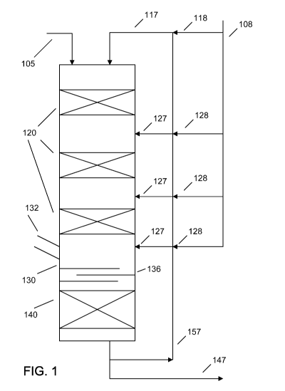
less, and possibly no, additional hydrogen.
[00651 The hydrogen solubility limit for a typical hydrocarbon feedstock can
generally
be from about 30 scf/bbl (about 5 Nm3/m3) to about 200 scf/bbl (about 34
Nm3/m3), which
applies to the total feed, including any portions of the feed that have been
previously
processed. As a result, mixing a recycled portion of feed with fresh feed can
increase the
hydrogen available for processing a fresh feed. By contrast, the solubility
limit of CO and
CO2 in (a typical hydrocarbon feedstock in) the continuous liquid phase can be
relatively low,
which means that continuous liquid phase reactions can advantageously
reduce/minimize any
potential poisoning of the hydroprocessing (e.g., dewaxing) catalyst due to
the CO and/or
CO2 generated, e.g., by hydrotreatment of a biocomponent feed.
[00661 Catalytic dewaxing relates to the removal and/or isomerization of
relatively
long-chain, paraffinic molecules from feeds. Catalytic dewaxing can be
accomplished by
selectively cracking and/or by hydroisomerizing these linear molecules.
Hydrodewaxing
catalysts can comprise molecular sieves such as crystalline aluminosilicates
(zeolites) or
silicoaluminophosphates (SAPOs). Additionally or alternately, the molecular
sieve can be a
1-D or 3-D molecular sieve, for example a 10-member ring 1-D molecular sieve.
Examples
of molecular sieves useful for dewaxing can include, but are not limited to,
ZSM-48, ZSM-
22, ZSM-23, ZSM-35, zeolite Beta, USY, ZSM-5, and combinations thereof. In a
preferred
embodiment, the molecular sieve can comprise ZSM-5, ZSM-22, ZSM-23, ZSM-35,
ZSM-
48, and combinations thereof, particularly ZSM-5, ZSM-48, and/or ZSM-23.
Optionally, the
dewaxing catalyst can include a binder, such as alumina, titania, silica,
silica-alumina,
zirconia, or a combination thereof, for example alumina and/or titania, or one
or more of
titania, silica, and zirconia. Additionally or alternately, a portion of the
catalyst in the
dewaxing reactor can comprise or be a hydrotreatment catalyst.
[00671 One feature of molecular sieves that can impact the activity of the
molecular
sieve includes the ratio of silica to alumina (Si/Al2) in the molecular sieve.
For instance, the
molecular sieve can have a silica to alumina ratio of about 200:1 or less, for
example about
120:1 or less, about 100:1 or less, about 90:1 or less, or about 75:1 or less.
Additionally or
alternately, the molecular sieve can have a silica to alumina ratio of at
least about 30:1, for
example at least about 50:1 or at least about 65:1.
CA 02800933 2012-11-27
WO 2012/012089 PCT/US2011/041756
-21 -
[00681 The dewaxing catalyst can also typically include a metal hydrogenation
component, such as a Group VIII metal. Suitable Group VIII metals can include
Pt, Pd, Ni,
or combinations thereof. Optionally, Co can be included in the aforementioned
list. The
dewaxing catalyst can include at least about 0.1 wt% of the Group VIII
metal(s), for example
at least about 0.3 wt%, at least about 0.5 wt%, at least about 0.6 wt%, at
least about 1.0 wt%,
at least about 2.5 wt%, or at least about 5.0 wt%. Additionally or
alternately, the dewaxing
catalyst can include about 10.0 wt% or less of the Group VIII metal(s), for
example about 5.0
wt% or less, about 2.5 wt% or less, about 1.5 wt% or less, or about 1.0 wt% or
less. In one
particular embodiment, the dewaxing catalyst can include from about 0.1 wt% to
about 1.5
wt% of Pt and/or Pd.
[00691 In some embodiments, the dewaxing catalyst can include as an additional
hydrogenation component at least one Group VIB metal, such as W and/or Mo.
Such Group
VIB metals can typically be used in conjunction with the at least one Group
VIII metal, such
as Ni and/or Co. An example of such an embodiment could be a dewaxing catalyst
that
includes NiW, NiMo, or NiMoW. When present, the dewaxing catalyst can include
at least
about 0.5 wt% of the Group VIB metal(s), for example at least about 1.0 wt%,
at least about
2.5 wt%, or at least about 5.0 wt%. Additionally or alternately, the dewaxing
catalyst can
include about 20.0 wt% or less of the Group VIB metal(s), for example about
15.0 wt% or
less, about 10.0 wt% or less, about 5.0 wt% or less, or about 1.0 wt% or less.
Where the
dewaxing catalyst contains only Group VIII metals, however, Pt and/or Pd
is(are) the
preferred Group VIII metal(s).
[00701 Catalytic dewaxing can be performed by exposing a feedstock to a
dewaxing
catalyst under effective (catalytic) dewaxing conditions. Effective dewaxing
temperatures
can be at least about 500 F (about 260 C), for example at least about 550 F
(about 288 C), at
least about 600 F (about 316 C), or at least about 650 F (about 343 C).
Additionally or
alternately, the temperature can be about 750 F (about 399 C) or less, for
example about
700 F (about 371 C) or less or about 650 F (about 343 C) or less. Effective
dewaxing
pressures can be at least about 200 psig (about 1.4 MPag), for example at
least about 400 psig
(about 2.8 MPag), at least about 500 psig (about 3.4 MPag), at least about 750
psig (about 5.2
MPag), or at least about 1000 psig (about 6.9 MPag). Additionally or
alternately, the
pressure can be about 2250 psig (about 15.5 MPag) or less, for example about
1500 psig
(about 10.3 MPag) or less, about 1200 psig (about 8.2 MPag) or less, about
1000 psig (about
CA 02800933 2012-11-27
WO 2012/012089 PCT/US2011/041756
-22-
6.9 MPag) or less, or about 800 psig (about 5.5 MPag) or less. Effective
dewaxing LHSVs
can be at least about 0.1 hr-1, for example at least about 0.2 hr-1, at least
about 0.5 hr-1, at least
about 1.0 hr-1, or at least about 1.5 hr-1. Additionally or alternately, the
LHSV can be about
15 hr-1 or less, for example about 10.0 hr-1 or less, about 5.0 hr-1 or less,
about 3.0 hr-1 or less,
or about 2.0 hr-1 or less. Further additionally or alternately, the
temperature, pressure, and
LHSV for a liquid-continuous reactor can comprise conditions suitable for use
in a trickle bed
reactor.
Continuous Liquid Phase Beds - Hydrotreating and/or Hydrofinishing
[00711 In some embodiments, the reaction stage having the continuous liquid
phase
environment can be configured for types of hydroprocessing other than
(catalytic) dewaxing,
e.g., hydrotreatment and/or hydrofinishing. Indeed, it is possible that the
continuous liquid
phase environment can be configured so that both dewaxing and another form of
hydroprocessing are attained therein, either simultaneously or separately
within a single
"stage". Particularly in such a multifunctional configuration, a mixture of
two or more types
of catalysts and/or a catalyst with multiple types of hydroprocessing activity
can be used.
[00721 In such multifunctional embodiments, the reaction conditions in the
stage having
the continuous liquid environment can comprise the effective hydrotreatment
conditions
described above, the effective dewaxing conditions described above, and/or
effective
hydrofinishing conditions. Note that, if effective hydrotreatment conditions
are used, the
treat gas rate can reflect the nature of the continuous liquid phase
processing environment,
and therefore can correspond to the amount of dissolved hydrogen in the liquid
phase
(including any non-continuous phase hydrogen gas, e.g., when the hydrogen need
exceeds the
solubility limit of dissolved hydrogen and additional gas phase hydrogen is
added).
[00731 A hydrofinishing stage can be relatively similar to a hydrotreating
stage, with
appropriately similar effective conditions. For example, hydrofinishing can
comprise
relatively mild hydrotreating, particularly directed to saturating (in this
context chemically,
not physically) any remaining olefins and/or residual aromatics. Effective
conditions for
hydrofinishing can include, but are not necessarily limited to, a temperature
from about
125 C to about 425 C, for example from about 150 C to about 350 C or from
about 180 C to
about 280 C, a total pressure from about 400 psig (about 2.9 MPag) to about
3000 psig
(about 20.7 MPag), for example from about 500 psig (about 3.4 MPag) to about
3000 psig
CA 02800933 2012-11-27
WO 2012/012089 PCT/US2011/041756
- 23 -
(about 20.7 MPag) or from about 1500 psig (about 10.3 MPag) to about 2500 psig
(about
17.2 MPag), and an LHSV from about 0.1 hr-1 to about 5 hr-1, for example from
about 0.5 hr-1
to about 3 hr-1 or from about 0.5 hr-1 to about 1.5 hr-1. The hydrogen treat
gas rate can be
based on the amount of hydrogen dissolved in the continuous liquid phase.
[00741 Due to the similarities between hydrotreating and hydrofinishing noted
above,
suitable catalysts for hydrofinishing can include hydrotreating catalysts,
such as the
hydrotreating catalysts described above.
[00751 Additionally or alternately, hydrofinishing catalysts can include
catalysts
containing Group VIB metals, Group VIII (non-noble) metals, and mixtures
thereof In an
embodiment, the sulfide of at least one of the metals can have a relatively
strong
hydrogenation function. Alternately, the hydrofinishing catalyst can include a
Group VIII
noble metal, such as Pt and/or Pd. These catalysts may include bulk metal
catalysts wherein
the amount of metal(s) is(are) about 50 wt% or greater based on catalyst.
Particularly in
embodiments where the catalyst is supported (and thus not a bulk catalyst),
the amount of
Group VIII metal(s) can be at least about 0.1 wt%, based on the total weight
of the catalyst,
for example at least about 0.5 wt%, at least about 0.6 wt%, at least about 0.7
wt%, at least
about 0.8 wt%, at least about 0.9 wt%, or at least about 1.0 wt%. Additionally
or alternately,
the amount of Group VIII metal(s) can be about 1.0 wt% or less, for example
about 0.9 wt %
or less, about 0.75 wt % or less, or about 0.6 wt % or less. Further
additionally or alternately,
the total amount of all metals, either individually or in mixtures, can be at
least about 0.1
wt%, for example at least about 0.25 wt%, at least about 0.5 wt%, at least
about 0.6 wt%, at
least about 0.75 wt%, or at least 1 wt%. Still further additionally or
alternately, the total
amount of all metals, either individually or in mixtures, can be about 35 wt%
or less, for
example about 20 wt% or less, about 15 wt% or less, about 10 wt% or less, or
about 5 wt% or
less.
[00761 When the catalysts are supported catalysts, suitable metal oxide
supports can
include low acidic oxides such as silica, alumina, silica-aluminas, titania,
and combinations
thereof, particularly comprising alumina. Preferred hydrofinishing catalysts
for aromatic
saturation (and/or hydrofinishing) can comprise at least one metal whose
sulfide exhibits a
relatively strong hydrogenation function on a porous support, which can
include amorphous
or crystalline oxide materials such as alumina, silica, and silica-alumina.
Additionally or
alternately, when present, the support materials may be modified, such as by
halogenation, or
CA 02800933 2012-11-27
WO 2012/012089 PCT/US2011/041756
-24-
in particular fluorination. The metal content of the catalyst can often be as
high as about 20
wt% for non-noble metals. Additionally or alternately, the hydrofinishing
catalyst can
include a crystalline material belonging to the M4 IS class or family, which
are mesoporous
materials having relatively high silica content, including but not limited to
MCM-41, MCM-
48, MCM-50, and combinations thereof (particularly comprising MCM-41). When
the M41S
materials include binders, suitable binders can include alumina, silica,
and/or any other
binder or combination of binders that provides a relatively high productivity
and/or a
relatively low density catalyst.
Product Properties
[00771 During hydrotreatment, the sulfur and nitrogen contents of the
feedstock can
preferably be reduced. The sulfur, nitrogen, and/or oxygen contents described
below can
represent the content in a treated feed after processing in the
hydroprocessing stage with a
continuous liquid phase environment. Additionally or alternately, the sulfur,
nitrogen, and/or
oxygen contents described below can correspond to a treated feed after the
last hydrotreating
stage having a continuous gas phase environment. For example, if the final
reaction stage(s)
having a liquid continuous environment is(are) operated under effective
catalytic dewaxing
and/or effective hydrofinishing conditions, the final reaction stage may have
little or no
impact on the amount of sulfur, nitrogen, and/or oxygen in the final liquid
product.
[00781 With regard to sulfur, one or more hydrotreatment stages can
advantageously
reduce the sulfur content to a suitable level, such to about 1000 wppm or
less, for example
about 500 wppm or less, about 100 wppm or less, about 50 wppm or less, about
30 wppm or
less, about 20 wppm or less, about 15 wppm or less, about 10 wppm or less, or
about 5 wppm
or less. With regard to nitrogen, the hydrotreating stage(s) can additionally
or alternately
reduce the nitrogen content of the feed to about 100 wppm or less, for example
about 50
wppm or less, about 20 wppm or less, about 15 wppm or less, about 10 wppm or
less, about 5
wppm or less, or about 3 wppm or less. Hydrotreatment can additionally or
alternately be
used to deoxygenate (e.g., substantially deoxygenate, which can correspond to
removing at
least 90 mol%, for example at least 95 mol%, at least 98 mol%, or at least 99
mol% of the
oxygen present, and/or which can correspond to reducing the oxygenate level to
0.1 wt% or
less, for example 0.05 wt% or less, 0.01 wt% or less, or 0.005 wt% or less)
the biocomponent
or other oxygen-containing feedstock. Deoxygenating a feed can avoid problems
with
CA 02800933 2012-11-27
WO 2012/012089 PCT/US2011/041756
-25-
catalyst poisoning and/or deactivation due to the creation of water or carbon
oxides during
hydroprocessing.
[00791 Typical mineral distillate feeds suitable for conversion into a diesel
fuel product
can have initial cloud points of at least about -5 F (about -21 C), for
example at least about
0 F (about -18 C), at least about 5 F (about -15 C), at least about 10 F
(about -12 C), at least
about 15 F (about -9 C), from about -4 F (about -20 C) to about 41 F (about 5
C), or from
about 25 F (about -4 C) to about 50 F (about 10 C). Similarly, the initial
cloud point of
typical biocomponent feeds can be up to about 70 F (about 21 C). As a result,
the
biocomponent feed and/or the mixed biocomponent/mineral feed can have a cloud
point of
about -5 C or more, for example about 0 C or more, about 5 C or more, about 10
C or more.
In various embodiments, a product from the dewaxing stage can be a distillate
product that
can be characterized by at least one cold flow property, such as a pour point,
a cloud point, a
cold filter plugging point, or a combination thereof. When a diesel fuel
product is produced
by the above methods, the diesel product can advantageously have a cloud point
at least about
C lower than the cloud point of the feed into the dewaxing stage, for example
at least about
C lower, at least about 20 C lower, at least about 30 C lower, at least about
40 C lower,
or at least about 50 C lower. Additionally or alternately, the cloud point of
the dewaxed
product can be about 0 C or less, for example about -5 C or less, about -10 C
or less, about -
C or less, or about -20 C or less. Further additionally or alternately, the
cloud point of the
dewaxed feed can be at least about -40 C, for example at least about -35 C, at
least about -
30 C, at least about -25 C, at least about -20 C, or at least about -15 C.
Still further
additionally or alternately, the product from the dewaxing stage can have at
least one cold
flow property that is at least about 10 C lower than the corresponding
property of the
feedstock, for example at least about 20 C lower or at least about 30 C lower.
Sample Reaction Systems
[00801 A reaction system suitable for carrying out the above process(es)
is(are) shown
schematically in FIG. 1. In FIG. 1, a hydrocarbon feedstock 105 is introduced
into a reactor.
The hydrocarbon feedstock 105 can be a biocomponent feed, a mineral feed, or a
mixture of a
biocomponent and a mineral feed. A mixed stream 117 of a hydrogen containing
gas flow
and a recycled product stream into which hydrogen is at least partially
dissolved can also be
introduced. The mixed stream 117 can be formed by mixing a hydrogen gas flow
118 from
CA 02800933 2012-11-27
WO 2012/012089 PCT/US2011/041756
-26-
hydrogen source 108 with a portion of recycled product 157. Optionally, the
hydrogen
containing gas flow and the recycled product stream could be introduced
separately.
Additionally or alternately, mixed stream 117 could optionally be combined
with
hydrocarbon feedstock 105 prior to entering the reactor.
[00811 The hydrocarbon feedstock 105 and mixed stream 117 can pass downstream
through the hydrotreating catalyst beds 120. The feedstock can be exposed to
the
hydrotreating catalyst beds 120 under effective hydrotreatment conditions in a
continuous gas
phase environment. After the last hydrotreating catalyst bed 120, the
resulting hydrotreated
effluent can enter a transition zone 130. In the embodiment shown in FIG. 1,
transition zone
130 can include a series of optional stripping trays 136. Note that the
presence of the
stripping trays does not necessarily require that a stripping gas is used. Gas
in the effluent
can be exhausted via one or more conduits 132. The liquid portion of the
effluent can
continue downstream to hydroprocessing stage 140, which can exhibit a
continuous liquid
phase environment. The effluent from hydroprocessing stage 140 can then exit
the reactor to
form a recycled product stream 157 and a diesel product stream 147. Portions
of the recycled
product stream 157 can be mixed with a hydrogen containing gas 128 to form
recycled
product inputs 127 that can enter the reactor, e.g., prior to each of the beds
after the first bed.
Recycled product inputs 127 can optionally include a gas phase hydrogen-
containing
component as well. The remaining portion of recycled product stream 157 can be
combined
with hydrogen-containing stream 118 to form the mixed stream 117. Optionally,
the final
recycled product input 127 can be introduced into the reactor downstream from
the transition
zone 130.
[00821 FIG. 2 schematically shows a portion of a reactor according to an
embodiment
of the invention. In FIG. 2, the portion of the reactor shown is the portion
downstream from
the final hydrotreating bed or stage having a continuous gas phase
environment. This portion
is shown to depict reactor internals that can be used in this type of
embodiment. In the
embodiment shown in FIG. 2, the effluent from the hydrotreating bed can pass
through
(relatively) inert catalyst bed 264 to enter transition zone 230. Optionally,
(relatively) inert
catalyst bed 264 can include (or be at least partially replaced by) other
types of internals, such
as holding trays, perforated plates, or the like, or any combination thereof.
After entering
transition zone 230, the gas can be exhausted via one or more conduits 232.
Optionally, one
or more holding trays, perforated plates, (relatively) inert catalyst beds,
stripping trays, or
CA 02800933 2012-11-27
WO 2012/012089 PCT/US2011/041756
-27-
other internals 266 can be included at the bottom of the transition zone.
After leaving the
transition zone, the liquid portion of the effluent can enter hydroprocessing
zone 240 that has
a continuous liquid phase environment.
[00831 FIG. 3 schematically shows a portion of a configuration according to an
embodiment of the invention. In FIG. 3, hydrotreating zone 320 is a
hydrotreating zone
having a continuous gas phase environment. The effluent from hydrotreating
zone 320 can
exit the reactor via conduit 387 and can thereafter enter a separation device
370, such as a
separator drum. In the separation device, a catalyst bed 340 can be included
in the lower
portion of the device, so that a hydroprocessing stage in a continuous liquid
phase
environment can be achieved. The gas phase portion of the effluent from
separation device
370 can exit via conduit 372. The liquid phase portion, which can first be
exposed to the
hydroprocessing bed 340 under effective hydroprocessing conditions, can exit
separation
device 370 via conduit 347.
[00841 FIG. 4 shows an example of a reaction system that can be used according
to the
invention. In FIG. 4, the entry point for fresh hydrocarbon feedstock 405 can
be located not
at the top of the reactor. Instead, the "top" reaction zone in the reactor can
be a continuous
liquid processing zone 440. In FIG. 4, a hydrocarbon feedstock 405 can be
introduced into
the reactor prior to the first continuous gas phase hydrotreating zone 420.
The hydrocarbon
feedstock 405 can be a biocomponent feed, a mineral feed, or a mixture
thereof. A hydrogen
gas flow 418 can be introduced prior to the first continuous gas phase
hydrotreating zone.
Optionally, the hydrogen containing gas flow 418 could be combined with
hydrocarbon
feedstock 405 prior to entering the reactor. The hydrocarbon feedstock can
additionally or
alternately be mixed with a portion of the effluent from continuous liquid
processing zone
440 not removed from the reactor as diesel product stream 447.
[00851 The hydrocarbon feedstock 405 (and optionally but preferably any
effluent from
zone 440) can pass downstream through the hydrotreating catalyst beds 420
under effective
hydrotreatment conditions in a continuous gas phase environment. After the
last
hydrotreating catalyst bed 420, the resulting hydrotreated effluent can be
separated into a gas
phase portion and a liquid phase portion, such as by using stripping trays
436. The gas phase
portion of the effluent can be removed from the reactor via conduit 432. The
liquid portion
of the effluent can continue "downstream" in the flow scheme of this reactor
via conduit 467
to hydroprocessing stage 440, which can have a continuous liquid phase
environment. At
CA 02800933 2012-11-27
WO 2012/012089 PCT/US2011/041756
-28-
least a portion of the effluent from hydroprocessing stage 440 can then exit
the reactor, e.g.,
as diesel product stream 447. Note that the exit conduit for diesel product
stream 447 is
shown with a gap in FIG. 4 only to clarify that diesel product stream is not
being mixed with
hydrogen source 408. One or more portions of the diesel product stream 447 can
be
separated off to make a recycled product stream 457. The recycled portion(s)
can be mixed
with a hydrogen containing gas 428 to form recycled product input(s) 427 that
can enter the
reactor prior to hydrotreating zones 420. Recycled product input(s) 427 can
optionally
include a gas phase hydrogen-containing component as well.
[00861 It is noted that the embodiments disclosed in FIGS. 2 and/or 3 can be
used
together or separately, in combination with the relevant portions of the
embodiments
disclosed in FIGS. 1 and/or 4.
Additional/Alternate Embodiments
[00871 Additionally or alternately, the invention can include one or more of
the
following embodiments.
[00881 Embodiment 1. A method for making a diesel fuel product, comprising:
contacting a feedstock with a hydrotreating catalyst in a plurality of
hydrotreating stages
under effective hydrotreating conditions, each hydrotreating stage having a
continuous gas
phase environment, at least a portion of the feedstock being comprised of a
biocomponent
feed, the feedstock having an oxygen content of at least about 1 wt% and a
sulfur content of
at least about 500 wppm, the feedstock having a first stoichiometric hydrogen
need for said
hydrotreating; mixing the feedstock, prior to or during contact with at least
one additional
hydrotreating stage, with a recycled product stream into which hydrogen is at
least partially
dissolved, the at least one additional hydrotreating stage being downstream
from at least one
of the plurality of hydrotreating stages; mixing the effluent from the
plurality of hydrotreating
stages with a second recycled product stream into which hydrogen is at least
partially
dissolved; separating the effluent from the plurality of hydrotreating stages
into a gas phase
effluent portion and a liquid phase effluent portion; and contacting the
liquid phase effluent
portion with a catalyst in a hydroprocessing stage having a continuous liquid
phase
environment under effective hydroprocessing conditions to form a diesel fuel
product, the
liquid phase effluent portion having a second stoichiometric hydrogen need for
said
hydroprocessing stage, the diesel fuel product being substantially
deoxygenated and having a
CA 02800933 2012-11-27
WO 2012/012089 PCT/US2011/041756
-29-
sulfur content of about 100 wppm or less, wherein the total treat gas rate of
hydrogen relative
to the feed is less than about 1.2 times the combined first and second
stoichiometric hydrogen
needs, and wherein the total hydrogen treat gas rate is about 750 scf/bbl
(about 130 Nm3/m3)
or less.
[00891 Embodiment 2. A method for making a diesel fuel product, comprising:
introducing a feedstock into a reactor, the reactor including one or more
hydrotreating stages
in a continuous gas phase environment and a dewaxing stage in a continuous
liquid phase
environment, at least a portion of the feedstock being comprised of a
biocomponent feed, the
feedstock having an oxygen content of at least about 1 wt% and having a cloud
point;
contacting the feedstock with hydrotreating catalyst in the one or more
hydrotreating stages
under effective hydrotreating conditions, the feedstock having a first
stoichiometric hydrogen
need for said hydrotreating stages; mixing the feedstock, prior to or during
contact with
hydrotreating catalyst in at least one hydrotreating stage, with a recycled
product stream into
which hydrogen is or becomes at least partially dissolved; mixing the
feedstock, prior to
contact with dewaxing catalyst in the dewaxing stage, with a second recycled
product stream
into which hydrogen is or becomes at least partially dissolved; exhausting
from the reactor a
gas phase effluent portion of a hydrotreated effluent from the one or more
hydrotreating
stages; and contacting a liquid phase effluent portion of said hydrotreated
effluent with
dewaxing catalyst in the dewaxing stage under effective dewaxing conditions to
form a diesel
fuel product, the liquid phase effluent portion having a second stoichiometric
hydrogen need
for said dewaxing stage, the diesel fuel product being substantially
deoxygenated and having
a cloud point at least about 10 C below the cloud point of the feedstock.
[00901 Embodiment 3. The method of embodiment 1 or embodiment 2, wherein
exhausting the gas phase effluent portion and/or separating the effluent from
the plurality of
hydrotreating stages is performed without using a stripping gas.
[00911 Embodiment 4. The method of any one of the previous embodiments,
wherein
the effective hydrotreating conditions include a temperature from about 500 F
(about 260 C)
to about 800 F (about 427 C), a total pressure from about 300 psig (about 2.1
MPag) to about
3000 psig (about 20.7 MPag), an LHSV from about 0.2 hr-1 to about 10 hr-1, and
a hydrogen
treat gas rate from about 300 scf/bbl (about 51 Nm3/m3) to about 10000 scf/bbl
(about 1700
Nm3/m3).
CA 02800933 2012-11-27
WO 2012/012089 PCT/US2011/041756
-30-
[00921 Embodiment 5. The method of any one of the previous embodiments,
wherein
the total treat gas rate of hydrogen is about 900 scf/bbl (about 150 Nm3/m3)
or less, for
example about 550 scf/bbl (about 93 Nm3/m3) or less.
[00931 Embodiment 6. The method of any one of the previous embodiments,
wherein
the hydrotreating catalyst comprises a Group VIB metal and Group VIII metal on
a support,
for example Mo and Co.
[00941 Embodiment 7. The method of any one of the previous embodiments,
wherein
the hydroprocessing stage contains dewaxing catalyst and is operated under
effective
catalytic dewaxing conditions, and wherein the effective catalytic dewaxing
conditions
include a temperature from about 500 F (about 260 C) to about 750 F (about 399
C), a total
pressure from about 400 psig (about 2.8 MPag) to about 1500 psig (about 10.3
MPag), and an
LHSV of about 0.2 hr-1 to about 10.0 hr-1.
[00951 Embodiment 8. The method of any one of the previous embodiments,
wherein
the dewaxing catalyst comprises a molecular sieve and a supported metal, the
molecular sieve
comprising ZSM-5, ZSM-22, ZSM-23, ZSM-35, ZSM-48, or a combination thereof,
for
example being ZSM-23 and/or ZSM-48.
[00961 Embodiment 9. The method of embodiment 8, wherein the supported metal
is
Pt and/or Pd, the amount of supported metal being from about 0.1 wt% to about
1.5 wt%.
[00971 Embodiment 10. The method of any one of embodiments 2-9, wherein a
recycled product stream is mixed with feedstock prior to or during each
hydrotreating stage,
the recycled product stream having hydrogen at least partially dissolved
therein.
[00981 Embodiment 11. The method of any one of the previous embodiments,
wherein
the feedstock comprises from about 10 wt% to about 50 wt% biocomponent feed,
or wherein
the feedstock comprises from about 50 wt% to about 90 wt% biocomponent feed.
EXAMPLES
Example 1: Reduced hydrogen consumption for processing feedstock including
biocomponent feed (soybean oil)
[00991 A mixture of a biocomponent diesel feed and a mineral diesel feed were
co-
processed under hydrotreatment conditions. The feed included about 30% by
weight of
soybean oil. Published reports indicate that the expected hydrogen consumption
for
hydrodeoxygenation and olefin saturation of soybean oil is between about 1500
scf/bbl (about
CA 02800933 2012-11-27
WO 2012/012089 PCT/US2011/041756
-31 -
250 Nm3/m3) and about 1900 scf/bbl (about 320 Nm3/m3). Based on this, about
1700 scf/bbl
(about 290 Nm3/m3) was selected as an expected hydrogen consumption for the
soybean oil.
The remaining -70 wt% of the mixed feed comprised a mineral feedstock
corresponding to a
light gasoil. The expected hydrogen consumption for this mineral light gasoil
feed was about
100 scf/bbl (about 17 Nm3/m3). Because the feed was about 30% soybean and
about 70% of
the mineral light gasoil, an expected hydrogen consumption for the blended
feed was
calculated to be about 580 scf/bbl (about 99 Nm3/m3).
[001001 The 30/70 mixture soybean and mineral oil feed was processed in the
presence
of an alumina-supported CoMo catalyst under two sets of conditions where the
ratio of treat
gas to feed was lower than the typically recommended ratio. The first set of
conditions
included a process temperature of about 625 F (about 329 C), an H2 partial
pressure of about
320 psig (about 2.2 MPag), a total treat gas ratio of about 1450 scf/bbl
(about 250 Nm3/m3) of
-80% hydrogen, corresponding to a hydrogen treat gas ratio of about 1160
scf/bbl (about 197
Nm3/m3), and an LHSV of about 0.6 hr-1. The hydrogen treat gas ratio in the
first set of
conditions corresponds to about two times the expected hydrogen consumption
for the mixed
feed. In the second set of conditions, the treat gas ratio was reduced to
about 780 scf/bbl
(about 130 Nm3/m3) for total gas (about 624 scf/bbl, or about 106 Nm3/m3, of
hydrogen),
which is less than about 110% of the hydrogen need. The target H2 partial
pressure was also
about 320 psig (about 2.2 MPag), but, due to natural process variations, a
hydrogen partial
pressure of about 311 psig (about 2.14 MPag) was measured at the outlet
(within reasonable
error; close enough to have minimal or no significant impact on the results).
[001011 The soybean oil portion of the feed contained roughly 10 wt% oxygen
content.
Because the feed was about 30% soybean oil, the total feedstock contained
about 3 wt%
oxygen content. Under the reaction conditions, at least about 98% of the
triglycerides in the
feed were converted. The oxygen content remaining in the hydrotreated (and/or
further
hydroprocessed) product was less than 0.1 wt%, which included oxygen gas
dissolved in the
feed. This level of oxygen removal is believed to be sufficient to allow use
in diesel fuel
applications.
[001021 The characteristics of the effluent from these two runs are shown in
Table 1. In
Table 1, the yield columns for CO, C02, and H2O include two numbers. The first
number
represents the measured yield, while the second number shows the corresponding
yield if the
feed had been 100% soybean oil. Table 1 shows that reducing the treat gas
ratio led to a
CA 02800933 2012-11-27
WO 2012/012089 PCT/US2011/041756
-32-
lower relative hydrogen consumption for the soybean oil. Table 1 also shows
that decreasing
the treat gas ratio resulted in a decrease in the yield of H2O and CO, though
an increase in
CO2 yield. The reduction in CO production was surprising, as prior reports of
processing at
reduced hydrogen partial pressures have shown increasing amounts of CO
production.
Without being bound by any particular theory, it is believed that the
combination of reduced
treat gas ratio and reduced hydrogen partial pressure can somehow facilitate
the water gas
shift reaction. This can lead to increased in situ hydrogen production and
thus a reduction in
CO production.
Table 1.
H2 Treat Gas Product CO Yield CO2 H2O Soy H2
Ratio [scf/bbl Sulfur [wt%] Yield Yield consumption
m3/m3 m [wt%] [wt%] [scf/bbl m3/m3
624 (106) 325 0.25 (0.8) 2.5 (8.4) 1.3 (4.2) 968 (165)
1160 197 125 0.5(l.6) 1.8(6.1) 1.7(5.6) 1223 208
Example 2: Reduced hydrogen consumption for processing feedstock including
biocomponent feed (palm oil)
[001031 At relatively high treat gas ratios, palm oil hydrogen consumption has
been
measured between about 1250 scf/bbl (about 210 Nm3"m3) and about 1500 scf/bbl
(about 250
Nm3"m3). This value can be reduced by using a relatively low treat gas ratio
and a relatively
low hydrogen partial pressure. Palm oil was co-processed in a feed with about
30 wt% palm
oil and about 70 wt% of a mineral light gasoil feed similar to that described
in Example 1.
For this 30/70 mixture of palm oil and light gasoil, the expected hydrogen
consumption was
calculated to be between about 450 scf/bbl (about 76 Nm3"m3) and about 520
scf/bbl (about
88 Nm3/m3). A treat gas ratio of about 650 scf/bbl (about 110 Nm3/m3) was used
to
hydrotreat the mixed feed in the presence of an alumina-supported CoMo
hydrotreatment
catalyst. The hydrogen consumption for the palm oil turned out to be less than
about 800
scf/bbl (about 140 Nm3/m3). The water yield was substantially reduced,
relative to an
expected water yield from processing at a treat gas ratio greater than two
times the expected
hydrogen need.
CA 02800933 2012-11-27
WO 2012/012089 PCT/US2011/041756
-33-
Example 3: Processing of a feedstock including biocomponent feed
[001041 The following is a prophetic example. The feedstock for the example is
a
mixture of a vegetable oil feed containing about 10 wt% oxygen and having an
expected
hydrogen consumption of about 1600 scf/bbl (about 270 Nm3/m3). This
biocomponent feed
is mixed with a mineral gasoil feed suitable for use as a diesel feedstock,
and having a sulfur
content of about 2 wt%. The expected hydrogen consumption for this feed is
about 160
scf/bbl (about 27 Nm3"m3). The biocomponent feed and the mineral feed are
mixed in a -1:3
ratio, to produce a total feed with an expected hydrogen consumption of about
520 scf/bbl
(about 88 Nm3/m3). The cloud point of the mixture is about 18 C.
[001051 This feedstock is introduced into a reactor that contains three
hydrotreatment
beds operated in a continuous gas phase environment, and one dewaxing catalyst
bed
operated in a liquid continuous environment. Recycled product feeds are
introduced into the
reactor at several locations. A portion of recycled product feed is introduced
at the top of the
reactor, while additional portions of recycled feed are introduced prior to
each of the catalyst
beds after the first catalyst bed. Hydrogen is dissolved in this recycled
product at
approximately the solubility limit prior to entering the reactor. The ratio of
fresh feed to total
recycled product in the reactor is about 1:2. The distribution of the recycled
product is that
about 40% of the recycled product enters the reactor at the top and/or with
the fresh feed,
while the remaining three recycled product streams each correspond to 20% of
the recycled
product. The recycled product has a hydrogen solubility of about 150 scf/bbl
(about 25
Nm3/m3). Based on the -1:2 ratio of fresh feed to recycled product, about 300
scf/bbl (about
50 Nm3/m3) of hydrogen enters the reactor as dissolved hydrogen. An additional
-500
scf/bbl (about 85 Nm3/m3) of hydrogen is introduced at or near the top of the
reactor, so that
an excess of hydrogen is available in the continuous gas phase hydrotreatment
zones of the
reactor. Alternately, an additional -220 scf/bbl (about 37 Nm3/m3) of hydrogen
could be
introduced into the reactor as a gas phase flow at or near the top of the
reactor, in which case
the total hydrogen treat gas rate of about 520 scf/bbl (about 88 Nm3/m3) would
match the
expected hydrogen consumption.
[001061 The hydrotreating catalyst beds contain a supported NiMo catalyst.
Effective
hydrotreating conditions are selected to achieve a final sulfur content of
less than about 100
wppm. The dewaxing catalyst bed contains a bound ZSM-48 catalyst containing
less than 1
wt% Pt.
CA 02800933 2012-11-27
WO 2012/012089 PCT/US2011/041756
-34-
[001071 After processing in the hydrotreatment stages in the continuous gas
phase
environment, with the dewaxing stage in the continuous liquid phase
environment, the
resulting liquid effluent has a sulfur content of less than about 100 wppm.
More than 99% of
the oxygen is removed. The cloud point of the liquid effluent is -3 C, which
is at least about
20 C lower than the initial feed.
[001081 While the present invention has been described and illustrated by
reference to
particular embodiments, those of ordinary skill in the art will appreciate
that the invention
lends itself to variations not necessarily illustrated herein. For this
reason, then, reference
should be made solely to the appended claims for purposes of determining the
true scope of
the present invention.