Note: Descriptions are shown in the official language in which they were submitted.
CA 02801214 2012-11-30
WO 2011/150985
PCT/EP2010/064847
METHOD AND SYSTEM FOR ONLINE FERRORESONANCE DETECTION
BACKGROUND OF THE INVENTION
1. Field of the invention
This invention relates to a method and a
system for online ferroresonance detection, especially
of power transformer ferroresonance.
2. Description of the related art
Ferroresonance is a phenomenon that is the
occurrence of an unstable high voltage, typically on
three phase electrical systems, which only occurs under
specific conditions.
Ferroresonance is a very dangerous phenomen
for transformer feeder or mesh corner and tee
connection constructions where there is a double
overhead line section.
Indeed, when a transformer feeder is
disconnected from the rest of a power system, the
transformer may be driven into saturation due to
discharge of the capacitance-to-earth of the isolated
system. Ferroresonance may then occur between the
reactive components, said ferroresonance being
maintained by energy transferred from the coupling
capacitance of the parallel line which remains on load.
When there is ferroresonance, the re-energized
transformer can cause severe switching overvoltages.
CA 02801214 2012-11-30
WO 2011/150985
PCT/EP2010/064847
2
Therefore a ferroresonance detection and alarm device
is essential.
Ferroresonance is a complicated nonlinear
electrical resonant phenomenon, which is caused by
saturable inductance of a transformer coupling with
system capacitance. This phenomenon, which can take
place for a wide range of situations in power systems,
is very dangerous for power systems due to
overvoltages, overcurrents and the abnormal rate of
harmonics it bring about, which may cause dielectric
and thermal destructions, reduction in performance and
lifetime of insulators, failure of the equipment (e.g.
untimely tripping of the protection devices), premature
ageing of the electrical equipments, even breakdown of
whole system.
The main characteristic of ferroresonance
is that it is highly sensitive to system parameters and
initial conditions, which makes it is hard to be
predicted.
There are four different modes of
ferroresonance according to the shape and frequency of
its voltage, said modes are the fundamental mode, the
subharmonic mode, the quasi-periodic mode and the
chaotic mode. The fundamental and subharmonic modes are
more frequent than the other two in power system.
Conventional UK practice has been to fit
ferroresonance detection which automatically initiates
isolation of the transformer from the de-energized line
by operation of an open terminal disconnector at the
onset of ferroresonance: when de-energized, if two out
CA 02801214 2012-11-30
WO 2011/150985
PCT/EP2010/064847
3
of three phases voltages remain high, the alarm will be
issued.
The document referenced [1] at the end of
the description describes a protection relay (XR 309)
made by the Reyrolle company. On supergrid systems,
ferroresonance may be experienced following de-
energisation of a directly connected transformer.
Ferroresonance may be sustained by the induction from
an energized parallel circuit. Re-energising the
transformer whilst in a ferroresonant state can risk
severe switching overvoltages, therefore where there is
such a risk a ferroresonance alarm relay is essential.
So the relay XR 309 detect ferroresonance, with the
system energized or de-energised, as follows :
- On system de-energisation, the secondary
voltage falls below the reset level, and three elements
drop-off. In the event of ferroresonance occurring, two
out of three elements will remain energized.
- If ferroresonance is induced onto a de-
energised system, the relay will only respond if the
amplitude of ferroresonance is above the relay element
pick-up level of 40V AC.
- Relay contacts are wired to initiate a
timer, which in turn will initiate the alarm.
This prior art method cannot cover all
ferroresonance situations: for example the only phase
high voltage case in the electrical rail circuits.
Another shortcoming of this relay is that it is not
numerical but analog. Therefore it cannot be
incorporated into the new protection relays.
CA 02801214 2016-11-25
4
The invention is related to the detection of
ferroresonance and determination of the mode of said
ferroresonance, especially in transformer feeder connection
conditions, or equivalent, such as mesh corner and circuit tee
connections, where a section of double circuit overhead lines
exists.
The purpose of the invention is to obtain an
accurate detection and mode recognition of ferroresonance, in
focusing on its most distinctive feature, which is transformer
iron core saturation, and its spectrum performance.
SUMMARY OF THE INVENTION
The invention concerns a method for online
ferroresonance detection in a high voltage electrical
distribution network, characterized in that it comprises:
- overflux detection, which acts as a start element, overflux
being set if the flux is greater than a threshold for a specified
time duration,
- mode verification, which is to recognize the modes of the
ferroresonance, a fuzzy logic method being used to discriminate
the ferroresonance modes.
Advantageously the invention method is a method for
ferroresonance detection for the power transformer feeder
conditions.
Advantageously in said method, for ferroresonance
detection, the flux is derived from integration of voltage with
elimination of the DC component, and then compared to an
adaptive threshold to determine whether there is overflux or
not.
CA 02801214 2012-11-30
WO 2011/150985
PCT/EP2010/064847
Advantageously many frequency components
are calculated when an overflux is detected, then many
(for example 20) latest
values of the frequency
components are stored, a stable state or an unstable
5 state being determined first by comparing the sum of
the standard deviation of each frequency component and
the sum of the expectations of each frequency
component. If the state is unstable and lasts for a
specified time duration, the chaotic mode is verified,
and if the state is stable, a fuzzy logic is applied to
discriminate the ferroresonance modes.
Advantageously the frequency components
are: 1/5 subharmonic component, 1/3 subharmonic
component, 1/2 subharmonic component, fundamental
component and 3rd harmonic component.
Advantageously the fuzzy logic uses a
selfdefined "large" membership function, each
component's value at the same instance being fuzzified
through said function, The rules being as follows:
- If Cl is large and C3 is large too, then it's
fundamental mode ;
- If Cl is large and C3 is not large, then it's normal
state ;
- If Cl is not large and C1/2 is large, then it's 1/2
subharmonic mode ;
- If Cl is not large and C1/3 is large, then it's 1/3
subharmonic mode ;
- If Cl is not large and C1/5 is large, then it's 1/5
subharmonic mode ;
C1,C3 being the components of fundamental and 3rd
harmonic respectively; C1/2, C1/3, C1/5 being the
CA 02801214 2012-11-30
WO 2011/150985
PCT/EP2010/064847
6
components of 1/2, 1/3, 1/5
subharmonics
respectively.The value of "not large" equals "1-large".
The rules' antecedents will be calculated by "MIN"
operator. The defuzzification will be achieved by
taking the corresponding mode of the rule with highest
antecedent as the result; if more than one rules with
the highest antecedent the result will be chaotic mode.
Advantageously a mode is verified if said
mode takes place more than 15 out the latest values.
Advantageously the flux is being monitored
all the time, and if two out of three phases fluxes
fall below a threshold, the transformer feeder is
regarded as de-energized. At such situation, the
threshold for overflux and mode verification is halved.
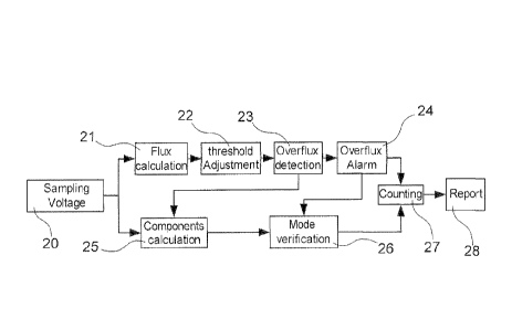
Advantageously the method comprises the
following steps:
= sampling voltage and
- on a first way:
= flux calculation,
= threshold adjustment,
= overflux detection,
= overflux alarm,
- on a second way:
= component calculation,
= mode verification,
and then :
- counting,
- report.
The invention also concerns a system for
online ferroresonance detection in a high voltage
CA 02801214 2012-11-30
WO 2011/150985
PCT/EP2010/064847
7
electrical distribution network, characterized in that
it comprises:
- Overflux detection means which acts as the start
element, overflux being set if the flux is greater than
a threshold for specified time duration,
- Mode verification means to recognize the modes of the
ferroresonance, which comprise a fuzzy logic means to
discriminate the ferroresonance modes.
Advantageously said system comprises means
for deriving the flux from integration of voltage with
elimination of the DC component, and means for
comparing it to an adaptive threshold to determine
whether there is overflux or not.
Advantageously the system comprises means
for calculating many frequency components when an
overflux is detected, and means for storing many latest
values (for example 20), a stable state or an unstable
state being determined first by comparing the sum of
the standard deviation of each frequency component and
the sum of the expectations of each frequency
component. If the state is unstable and lasts for a
specified time duration, the chaotic mode is verified,
and if the state is stable, a fuzzy logic is applied to
discriminate the ferroresonance modes.
Advantageously the frequency components
are: 1/5 subharmonic component, 1/3 subharmonic
component, 1/2 subharmonic component, fundamental
component and 3rd harmonic component.
Advantageously the fuzzy logic uses a
selfdefined "large" membership function, each
CA 02801214 2012-11-30
WO 2011/150985
PCT/EP2010/064847
8
component's value at the same instance being fuzzified
through the function, the rules being as follows :
- If Cl is large and C3 is large too, then it's
fundamental mode ;
- If Cl is large and C3 is not large, then it's normal
state ;
- If Cl is not large and C1/2 is large, then it's 1/2
subharmonic mode ;
- If Cl is not large and C1/3 is large, then it's 1/3
subharmonic mode ;
- If Cl is not large and C1/5 is large, then it's 1/5
subharmonic mode ;
C1,C3 being the components of fundamental and 3rd
harmonic respectively; C1/2, C1/3, C1/5 being the
components of 1/2, 1/3, 1/5 subharmonics respectively.
The value of "not large" equals "1-large". The rules'
antecedents will be calculated by "MIN" operator. The
defuzzification will be achieved by taking the
corresponding mode of the rule with highest antecedent
as the result; if more than one rules with the highest
antecedent the result will be chaotic mode.
Advantageously one mode is verified if said
mode takes place more than 15 out the latest values.
Advantageously the flux is being monitored
all the time, and if two out of three phases fluxes
fall below a threshold, the transformer feeder is
regarded as de-energized. At such situation, the
threshold for overflux and mode verification is halved.
Advantageously the system comprises
successively :
CA 02801214 2012-11-30
WO 2011/150985
PCT/EP2010/064847
9
- a filter receving a voltage input,
- an A/D converter,
- a data storage,
- a processor,
- an amplifier,
- an alarm output device, which outputs an alarm
output,
and also comprises an user interface connected to the
processor.
The invention makes it possible to detect
the occurrence of ferroresonance online, which is
applicable on power transformers. The invention uses
the overflux as start element, in evaluating the
different feature frequencies components with a fuzzy
logic method to verify the occurrence of ferroresonance
meanwhile determining its mode. Based on combination of
overflux detection and mode verification, the invention
can overcome the difficulties of conventional relaying
algorithm and fills the blanks of the numerical
ferroresonance detection method.
Advantageously the invention can be
incorporated into a new digital protection relay. It is
more sensitive and accurate, in covering all the cases
and modes of ferroresonance especially on power
transformer.
BRIEF DESCRIPTION OF THE DRAWINGS
Fig. 1 is a block diagram of the invention
system.
Fig. 2 is a "large" membership function.
CA 02801214 2012-11-30
WO 2011/150985
PCT/EP2010/064847
Fig. 3 is a diagram of the organization of
invention method.
Fig.4 is the diagram of the organization of
the mode verification.
5
DESCRIPTION OF THE PREFERRED EMBODIMENTS
The invention scheme is based on overflux
detection and frequency components evaluation.
Saturation of iron core inductance is a premise to
10 ferroresonance. So overflux is a good indicator of
ferroresonance. Based on the 150Hz, 50Hz, 25Hz, 162/3Hz,
10Hz components of the voltage, with 50Hz as the
fundamental system frequency (or on 180Hz, 60Hz, 30Hz,
20Hz and 12Hz with 60Hz), a fuzzy logic method is used
to determine the mode of ferroresonance. If the flux
keeps high for a specified time with distorted voltage
waveform, ferroresonance is assumed to have occurred.
1) Overflux detection
There are several ways to detect overflux,
for example to detect V/f > Vfl/fn (V: voltage, f:
frequency) or to detect the 5th harmonic. But, due to
the distortion of the waveform and subharmonic mode of
ferroresonance, such methods are not applicable for the
overflux detection in ferroresonant condition. The
invention scheme adopts another approach, which is a
direct calculation of flux by integration of voltage.
flux = ft udt + fluxo
J
(1)
The initial value of the flux being not
known, the DC component of the flux is removed through
the following formula :
CA 02801214 2012-11-30
WO 2011/150985
PCT/EP2010/064847
11
fluxõ = ¨1 ft fluxdt
T t-T
(2)
Flux = flux- flux,c
(3)
This operation also can avoid interference
of the inrush current caused overflux.
The magnitude of the flux can be obtained
by the following formula:
\
Magflux = I ¨1 fFlux2dt
T t-T
(4)
When the flux is greater than a threshold
(1.2 by default), it is said to be an overflux. The
components starts to be calculated. If this situation
lasts for a specified time duration, one overflux alarm
is then issued to initiate the mode verification part.
2) Mode verification
There are several modes of ferroresonance:
the fundamental mode, the subharmonic mode, the quasi-
periodic mode and the chaotic mode. The mode
verification determines the mode of the ferroresonance.
Fundamental frequency, 3rd harmonic, 1/2 sub-harmonic,
1/3 sub-harmonic, and 1/5 sub-harmonic components are
calculated by DFT (Discrete Fourrier Transform). The
mode verification is based on evaluation of these
frequency components.
Due to the unpredictable and changeable
feature of ferroresonance, a fuzzy logic is used to
determine the mode.
With the latest 20 values of each frequency
component calculated, a 5*20 matrix is formed, which
has the following aspect:
CA 02801214 2012-11-30
WO 2011/150985
PCT/EP2010/064847
12
Components \Time To+At T0+2At ¨ = = T0+20At
Fundamental Cl (1) Cl (2) ..... Cl (20)
3rd harmonic C3 ( 1 ) C3(2) ..... C3(20)
1/2 Subharmonic C1/2(1) C1/2(2) ..... C1/2(20)
1/3 Subharmonic C1/3(1) C1/3(2) ..... C1/3(20)
1/5 Subharmonic C1/5(1) C1/5(2) ..... C1/5(20)
For each row or component, the expectation
and the standard deviation are calculated. If the sum
of the standard deviation of the five rows divided by
the sum of the expectation of the five rows is greater
than a determined threshold, the considered state is
regarded as unstable pre-chaotic state. If this
unstable pre-chaotic state continues for specified time
duration it is regarded as chaotic ferroresonance.
Otherwise if the considered state is stable, a simple
fuzzy logic algorithm is applied to get the mode
information.
Each value is fuzzified by a "large"
membership function as shown on Fig. 2.
The definition of such a function is the
following one:
{ 0 CN K1
M(CN) = (K2 ¨K1) x (CN¨KI) K1 <CN 1C2
1 K2 <CN
While M is the "large" value of Cn, K1 and
K2 are two inflection points for this function.
Different frequency components have different K1 and K2
for fundamental frequency, K1 could be around 0.7-0.9,
K2 could be 1.2-1.4; 3rd harmonic component's
corresponding K1 could be 0.2-0.4, K2 could be 0.3-0.5;
CA 02801214 2012-11-30
WO 2011/150985
PCT/EP2010/064847
13
1/2, 1/3, 1/5 subharmonics' corresponding K1, K2 will
be 1/2, 1/3, 1/5 of the value of fundamental components
corresponding K1, K2. This is because by integration,
the flux derived from 1/2, 1/3, 1/5 subharmonics will
be 2, 3, 5 times of that derived by the fundamental
frequency voltage when they are of the same amplitude.
The parameters of such a function are
different for different components. For each column of
the above matrix:
- if Cl is large and 03 is large too, then it's
ferroresonance fundamental mode ;
- if Cl is large and 03 is not large, then it's normal
state ;
- if Cl is not large and C1/2 is large, then it's
ferroresonance 1/2 subharmonic mode ;
- if Cl is not large and C1/3 is large, then it's
ferroresonance 1/3 subharmonic mode ;
- if Cl is not large and C1/5 is large, then it's
ferroresonance 1/5 subharmonic mode ;
The value of "not large" equals "1-large".A
min fuzzy operator is used to obtain the antecedent.
For example, if "Cl is large" equals 0.2, "C3 is large"
equals 0.5, "C1/3 is large" equals 0.9, and then the
first "if-then" rule's antecedent is 0.2, the second
rule gets 0.5, and the third rule gets 0.8.
The defuzzification works is such that a
column is set to be the mode correspondent to the
highest antecedent; if more than one rule with the
highest antecedent, the column is set to be chaotic
mode.
CA 02801214 2012-11-30
WO 2011/150985
PCT/EP2010/064847
14
Among 20 columns, if there are more than 15
columns belonging to the same mode, this mode is
verified.
3) The adaptive settings
An adaptive threshold is adjusting itself
according to the amplitude/power conditions. If two
phases' fluxes drop significantly, it indicates the
line being deenergized. The overflux threshold is
adjusted to a small value to increase the sensitivity.
Detail description of a preferred embodiment
The invention is implemented into a
sampling and alarming system as shown on Fig. 1. The
block diagram of said invention system comprises
successively :
- a filter 10 receving a voltage input,
- an A/D converter 11,
- a data storage 12,
- a processor 13,
- an amplifier 14,
- an alarm output device 15, which outputs
an alarm output.
It also comprises an user interface 16 connected to the
processor 13.
Basically, the invention system keeps
sampling the three phases voltages. Also this system
performs the algorithm, or invention method, in real
time. In this embodiment, it executes the algorithm
every half power cycle. The system is able to sample at
the rate to exactly N points per power cycle (N=24 for
example). The system frequency is set at 50Hz or 60Hz.
CA 02801214 2012-11-30
WO 2011/150985
PCT/EP2010/064847
The system is able to retrieve the history sample value
at every execution point.
There are four stages for the algorithm:
PREPARE, IDLE, START, and ALARM:
5 - the PREPARE stage is when first enabled for the input
to full fill the voltage buffers,
- the IDLE stage is normally running stage, flux being
monitored.
- the START stage is when a overflux is detected.
10 - the ALARM stage is when the ferroresonance mode is
verified and the alarm is issued.
Fig. 3 shows the whole process of the
invention method. It comprises the following steps:
= sampling voltage 20, and
15 - on a first way:
= flux calculation 21,
= threshold adjustment 22,
= overflux detection 23,
= overflux alarm 24,
- on a second way:
= component calculation 25,
= mode verification 26,
and then :
- counting 27,
- report 28.
1) Overflux detection
The flux buffer utilizes a 144-points array
corresponding to 6 fundamental power cycles, in order
to minimize the interaction between the subharmonics.
When 5 subharmonic ferroresonance happens, the flux
CA 02801214 2012-11-30
WO 2011/150985
PCT/EP2010/064847
16
calculation based on the 144 points cause some
deviation which is acceptable.
Practically, the flux flux(n), its DC
component fluxBc and the magnitude Mag are calculated
though discrete form :
flux(n)= flux(n ¨1) + u(n)At (5)
1 N
flux õ = ¨ L flux(n)
N n=1 ( 6 )
flux(n) = flux(n)¨ fluxõ
(7)
1 N
Magx, = \I¨ L flux2 (n)
N n,1
(8)
In order to simplify the calculation,
equation (5) and (8) are replaced by equation (9) and
(10) .
flux(n) = flux(n -1) + u(n); (9)
Where U(n) is normalized voltage, and the
initial value of flux is set to 0.
\11 N
Mag flux = ¨ L flux2 (n)* Kn
N n,1
(10)
Where the constant Kn is used for
normalization.
Kn = (11 Ncycle I Frequency I tB) A 3 /7c = 0.0057155766
When Ncycle=24 and system frequency is 50Hz
tB is the base value of time which equals to
1/27c /Frequency .
When Magflux is greater than the threshold,
the algorithm enters the START stage.
2) Mode verification
CA 02801214 2012-11-30
WO 2011/150985
PCT/EP2010/064847
17
Once entered into the START stage, the
invention method begins to calculate the components of
the fundamental frequency, the 3rd harmonic, the 1/2
sub-harmonic, the 1/3 sub-harmonic, and the 1/5 sub-
harmonic by DFT.
Three 144-points arrays are used to store
the three voltages signals for the calculation of the 5
frequency components: fundamental component, 3rd
harmonic component, 1/2 subharmonic component, 1/3
subharmonic component, 1/5 subharmonic component. In
order to minimize the interaction of the different
frequency components in calculation by DFT, the
components of 150Hz, 50Hz, 25Hz and 162/3Hz are
calculated at 81/3Hz basis, which need data of 6
fundamental cycles, i.e. 144 points. Only the 1/5
subharmonic frequency component is calculated at 10Hz
basis, corresponding to 5 fundamental cycles, i.e. 120
points. This compromise can be taken, because the
interaction between 1/3, 1/2, 1/5 subharmonic
calculations is not too big meanwhile the bandwidth
consumed for the ferroresonance is acceptable.
The overflux alarm starts the mode
verification. The mode verification is carried out
every 10 power cycles. Unless the mode verification
gets the NORMAL results, an ferroresonance alarm (FRD-
ALARM) is issued. The mode verification, as shown in
the fig. 4, comprises the following steps:
- trigger by overflux alarm (30),
- get the 5*20 matrix (31),
- calculate each row's deviation and expect
(32),
CA 02801214 2012-11-30
WO 2011/150985
PCT/EP2010/064847
18
- verify if sum (deviation)/sum (expects) >
value K (33),
1) If "yes"
- chaotic-timer running (34),
- verify if chaotic-timer run out (35),
a) if "yes"
- set FRD mode (ferroresonance mode) to be
chaotic (34),
2) If "no"
- check each column's mode case (37),
- verify either mode appears more than 15
cases (38),
a) if "no" go to the previous step entitled
"chaotic timer running",
b) if "yes"
- set FRD mode to be the searched mode
(39),
- reset chaotic timer (40),
and then
- verify if FRD mode is normal (41),
a) if no
- set state to be FRD alarm (42).
3) The adaptive settings
The flux is being monitored all the time.
If two out of three phases' fluxes fall below a
threshold, the transformer feeder is regarded as de-
energized. At such situation, the threshold for the
overflux and the mode verification are halved.
CA 02801214 2012-11-30
WO 2011/150985
PCT/EP2010/064847
19
REFERENCES
[1] "Ferroresonance alarm relay type XR 309
(Fact sheet, Reyrolle protection, 1996, Roll-Royce)