Note: Descriptions are shown in the official language in which they were submitted.
CA 02801317 2013-01-09
GROUT TUBE HOLDER AND SPACER
BACKGROUND OF THE INVENTION
[0001] There are numerous concrete products used in the construction industry
in a
variety of applications, such as foundations for supporting structures, as
bridge and
deck panels, and as beams for structures, just to name a few. Concrete is a
material
that is very strong in compression but relatively weak in tension. Masonry
structures and
the mortar holding them together have similar properties to concrete and also
have a
limited ability to carry tensile loads.
[0002] In order to compensate for this imbalance in the behavior of concrete
and
masonry structures, reinforcement bars, which are common steel bars, are
typically
used as a tensioning device to produce reinforced concrete and reinforced
masonry
structures. These reinforcement bars, commonly called "rebars", are usually
formed
from carbon steel, and are given ridges for better mechanical anchoring into
the
concrete. While any material with sufficient tensile strength could
conceivably be used
to reinforce concrete, steel and concrete have similar coefficients of thermal
expansion.
Therefore, a concrete structural member reinforced with steel will experience
minimal
stress as a result of differential expansions of the two interconnected
materials caused
by temperature changes.
[0003] Traditional reinforced concrete is based on the use of rebars cast into
a poured
concrete structure. In addition, pre-stressed concrete is a method for further
overcoming
concrete's natural weakness in tension. It can be used to produce beams,
floors or
bridges with a longer span than is practical with ordinary reinforced
concrete. Pre-
1
CA 02801317 2013-01-09
stressing tendons, generally of high tensile steel cable, are used to provide
a clamping
load which produces a compressive stress that balances the tensile stress that
the
concrete compression member would otherwise experience due to a bending load.
[0004] One concrete product that utilizes the foregoing principles is a
prefabricated
concrete pile used to support foundations. These piles are driven into the
ground using
a device such as a pile driver. Concrete piles are available in a variety of
cross-sectional
shapes, including square, octagonal, and round cross-sections, and they are
reinforced
with rebar and are often pre-stressed. Foundations relying on concrete driven
piles
often have groups of piles connected by a pile cap (a large concrete block
into which
the heads of the piles are embedded) to distribute loads which are larger than
one pile
can bear. Pile caps and isolated piles are typically connected with the piles
to tie the
foundation elements together, so that lighter structural elements bear on the
piles while
heavier elements bear directly on the pile cap.
[0005] In the manufacture of reinforced and pre-stressed concrete structures,
such as
piles, a form of the desired shape is used with reinforcing spaced-apart steel
bars
positioned to create a frame. Then rebars or grout tubes are used to further
strengthen
the structure. When utilized, the rebars or grout tube must be centered and
held in
place as the concrete is poured to form the structure. Securing the rebars or
grout tube
within the steel bar frame is currently done by hand, using wires and cables
to tie the
rebars or grout tube to the frame. This is a time consuming and expensive
process.
[0006] There is therefore a need for an improved way of securing a grout tube
and
rebars in place while the concrete is poured to form the concrete structure.
2
CA 02801317 2013-01-09
SUMMARY OF THE INVENTION
[0007] The invention is for preformed wire spacers that are shaped to grasp a
grout
tube and secure it to the steel frame within a concrete form. The spacer is
formed from
a continuous length of spring steel wire that has a circular central portion
of sufficient
size to surround the grout tube. The free ends of the spacer extend outwardly
from the
central portion and are formed with hooks extending, with one free end having
both a
handle and a hook. Being a continuous length of spring steel, the central
portion has a
double wrap or overlapping portion which provides for the diameter of the
central portion
to be temporarily expanded in diameter by grasping the free ends and applying
force to
expand the central portion's size. This allows the spacer to be easily
combined with the
grout tube, since the spacers and tube can move relative to each other.
Multiple
spacers are used on a single tube and are spaced apart a distance to provide
the
proper support and positioning of the tube relevant to the frame and the
finished
concrete form.
BRIEF DESCRIPTION OF THE DRAWINGS
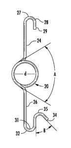
[0008] Fig. 1 is a front view of a first embodiment of the invention;
[0009] Fig. 2 is a side view of the first embodiment of the invention;
[0010] Fig. 3 is a perspective view of the invention;
[0011] Fig. 4 is a perspective view of a steel frame for a concrete beam which
shows
the spacers secured in place on the steel frame;
[0012] Fig. 5 is a perspective view showing a grout tube with spacers in place
to
illustrate the positioning of the spacers on the tubes; and
3
CA 02801317 2013-01-09
[0013] Fig. 6 is a perspective view of a finished concrete beam and shows the
opening
created by the grout tube.
DETAILED DESCRIPTION OF THE INVENTION
[0014] Figs. 1, 2 and 3 show the preferred embodiment of the invention. A
spacer 20
comprises a central portion 22 and a pair of free ends 24. The free ends 24,
26 extend
outwardly from the central portion 22. Preferably the free ends 24, 26 extend
in
opposite directions and are one-hundred eighty degrees apart. The spacer 20 is
formed
from a single continuous length of spring steel wire.
[0015] In the preferred embodiment, the central portion 22 transitions to the
free ends
24, 26 at an angle. Additionally, the angle designated as A in Fig. 1 is
preferably
between 60 and 90 degrees, with 75 degrees being shown in Fig. 1. The angle A
can
have an effect on the force needed to expand the central portion 22 as further
discussed below.
[0016] Free end 24 has a fastener 27 which is preferably a hook 28 formed at
its outer
end 29 while free end 26 has a fastener 31, again preferably a hook 32, and a
handle
34 at its outer end 35. The hooks 28, 32 engage a frame 40 of a future
concrete
structure as shown in Fig. 4. Hooks 28, 32 grasp rebars 44 that form the frame
40 for
the concrete structure, or, can be hooked over cables 46 on opposite sides of
the frame
40. The preferred embodiment has the handle 34 on one free end only, in the
figures,
free end 26.
[0017] Handle 34 provides a grip for installing the spacer 20 by first
securing the hook
28 over a portion of the frame 40 or cable 46 after which handle 34 is grasped
to secure
4
CA 02801317 2013-01-09
the hook 32 over a portion of the frame 40 or the cable 46 on the opposite
side of the
frame 40. Again, the angle of the handle 34 and the hook 32 can be varied,
however,
the angle designated as B shown in Fig. us approximately 45 degrees. The angle
B
can allow a user easier access to the handle and allow the user to more easily
apply
force to the spacer 22 during installation.
[0018] The curved portions 50 of the spacer 20 are contiguous and form a
secondary
structure 52 in the central portion 22. Preferably the curved portions 50
touch against
each other within at least a portion of the central portion 22, as shown in
Figs. 2 and 3.
The secondary structure 52 in the preferred embodiment is a loop 54 which is
circular.
This structure and the use of spring steel for the spacer 20 provide for quick
and easy
installation of the spacer 20 on the frame 40.
[0019] Once spacers 20 are installed on the frame 40, a grout tube 12 can
easily be
slid through the spacers which position the grout tube 12 in the approximate
center of
the form resulting in a finished product as shown in Fig. 6. Fig. 5 shows a
grout tube 12
with spacers 20 installed on it. In this instance, the grout tube 12 can be
positioned
inside the frame 40 and the spacers 20 hooked onto the frame 40 in the manner
described above. In either case, it is evident that use of spacers 20 greatly
reduces the
time and effort to produce concrete products of this type and therefore
significantly
reduces the cost of the products a reinforced concrete beam or concrete pile
10
produced using a grout tube 12. Referring to Fig. 6, the grout tube 12
provides an
opening through which rebars (not shown) can be inserted to anchor the pile or
beam
in place in a structure where beams 10 or piles are used.
5
CA 02801317 2013-01-09
[0020] As is well known to those skilled in the art, a typical concrete pile
or beam 10 is
produced in a concrete form (not shown) of the desired length and cross-
sectional
shape. Referring to Fig. 4, the pile or beam almost always is produced using
rebars 14
to form the frame 40 and high tensile cables 46 which may be pre-stressed, as
described above. Fig. 4 illustrates the skeleton metal frame in which a grout
tube 12 can
be placed.
[0021] Although it is contemplated that the spacer 20 will have a set diameter
"d" for
accommodating a specific sized grout tube, the size of the spacer 20,
particularly the
diameter of the central portion 22 can be varied during the manufacturing
process to
accommodate a specific sized grout tube. Additionally, the preferred material
used to
make the spacer 20 is spring steel which allows the spacer to have some
flexibility. The
flexibility allows the spacer 20 to go from its static first position to a
second position
when force is applied on the free ends 24, 26 toward the center portion 22.
This
application of force expands the diameter of the center portion 22. The
greater the
force applied the greater the expansion of the diameter of the center portion.
Once the
force is released, the spacer 20 returns to its normal first position. The
ability to expand
allows a particular spacer 20 to accommodate a variety of sizes of grout
tubes.
[0022] The above description is for a preferred embodiment. There are numerous
contemplated changes to the spacer which could vary from the preferred
embodiment.
Beginning with the free ends 24, 26, a variety of fasteners, other than hooks,
with the
ability to engage a portion of the frame 40 or cables 46. Similarly, the shape
of the
center portion 22 could be varied without making the spacer 20 inoperable.
Furthermore, another embodiment could utilize a center portion 22 which does
not
6
CA 02801317 2013-01-09
entirely wrap around the grout tube. Instead, the center portion 22 could be a
semi-
circle which wraps around only a portion of the grout tube 12. For instance,
if the center
portion wrapped the left side of the grout tube 12, then the next flanking
spacer 20 could
wrap the right side of the grout tube 12. Accordingly the grout tube 12 could
be secured
within the frame 40 without a complete circular center portion 22.
[0023]
Having thus described the invention in connection with certain embodiments,
it will be obvious that the same may be varied in many ways. Such variations
are not to
be regarded as a departure from the spirit and scope of the invention, and all
such
modifications as would be obvious to one skilled in the art are intended to be
included
within the scope of the invention.
7