Note: Descriptions are shown in the official language in which they were submitted.
1
Wear assembly for machinery
TECHNICAL FIELD
A wear assembly comprising a retaining pin, a wear element and a support
element is herein disclosed. The wear assembly is particularly suitable for,
but
not limited to, any type of industrial machinery or equipment having parts
subjected to wear.
A retaining pin for attaching a wear element to a support element to each
other is
also disclosed.
Furthermore, a wear element is also disclosed herein.
BACKGROUND ART
Wear assemblies are widely known in different types of industrial machinery or
equipment such as, for example, excavating machinery, e.g. excavators,
bulldozers, angle-dozers, mechanical shovels, shovel loaders, road rollers,
tamping machines, dragline buckets, etc, and in general earth-moving equipment
and material displacement machinery having parts subjected to wear.
It is known in the art to provide such industrial machinery or equipment with
wear
elements, also referred to as fingers, tips or tooth points. The wear elements
are
mechanically adapted to engage and displace materials such as earth. In use,
the wear elements are attached the machinery through a support element, also
referred to as adapter. The support element or adapter can be engaged to or be
part of the machinery itself.
Mutual attachment of wear elements and support elements in machinery is
commonly carried out through corresponding retaining pins. The wear elements
and the support elements attached through corresponding retaining pins form
the
respective wear assemblies.
CA 2801528 2017-11-24
CA 02801528 2013-01-08
2
The parts of the wear assembly, specially the wear elements, operate in harsh
working conditions and they are subjected to very heavy loading and a high
degree of wearing in use. The purpose of the wear elements is typically to
protect
the support element or parts of the machinery from premature wear. The wear
elements wear out frequently and require periodic replacement. Therefore a
quick and easy removal is required while ensuring that the wear elements and
the support elements are securely mounted in order to withstand the
considerable forces exerted on both elements during operation.
The configuration of retaining pin as well as the portion of the wear element
and
the support element where the retaining pin is received is of great
importance.
For attaching the wear elements to the corresponding support elements, the
retaining pins are typically forcibly driven into aligned portions of the wear
element and the support element. This is carried out by hitting a tool such as
a
sledge hammer or the like until the retaining pin has been properly inserted
into
the wear element and the support element. Detaching the wear element from the
support element require the corresponding retaining pin to be forcibly pounded
out. This can give rise to a safety hazard for the operator in installing and
removing operations. In addition, in such installing and removing operations
the
retaining pin may become deformed, so its extraction may become a difficult
operation.
Document W02011125794 discloses a retaining pin for attaching a wear
element to a support element. Bushings, bolts, and washers are provided to
prevent the retaining pin from falling off the wear element and the support
element.
Document US4918843 also discloses a retainer pin assembly for attaching a
wear element to a support element. The retainer pin assembly comprises a
spring retainer, a retainer pin, and a holder.
Both prior art solutions suffer from the disadvantage that several pars are
necessary in combination with the retaining pin for attaching the wear element
to
the support element involving undesirably complexity and high costs.
,
3
Document W02005095720 also discloses a retaining pin for attaching two
mechanical parts to one another in a detachable manner. The retaining pin and
the mechanical parts to be attached to each other are configured such that as
the
retaining pin is rotated it becomes locked (or unlocked). This is carried out
by
means of the provision of two or more inclined surfaces in conjunction with
elastically loaded tension elements projecting in the axial direction of the
pin.
Document US5983534 provides a lock structure for attaching a wear element to a
support element. When the support element is received into the lock structure
it
can be axially inserted therein in a first rotational orientation and then
forcibly
rotated to a second rotational orientation. The wear and support elements have
openings which surfaces are configured to radially inwardly displace a force
exerting member in response to such rotation causing a continuous resilient
force
to be exerted to the elements tending to tighten them to each other. As the
lock
structure is rotated during its installation, a ramped surface on the support
element permits it to snap into a retaining pocket thereon preventing further
rotation of the lock structure.
These above prior art solutions have the disadvantage that the provision of
parts
having inclined planes or surfaces configured in correspondence with tension
elements renders the arrangement complex and therefore the whole assembly
capital intensive.
A need still exists for an improved wear assembly in which parts involved
therein
can be easily, quickly and safely attached and detached, for example in
maintenance and/or repair operations.
SUMMARY OF THE INVENTION
A wear assembly comprising a retaining pin, a wear element and a support
element is herein disclosed suitable for but not limited to industrial
machinery or
equipment.
CA 2801528 2017-11-24
4
A retaining pin for attaching a wear element to a support element to each
other is
also disclosed.
A wear element is also disclosed herein.
The wear element of the present wear assembly may correspond to the finger,
tip
or tooth point in machinery such as excavators, bulldozers, angle-dozers,
mechanical shovels, shovel loaders, road rollers, tamping machines, dragline
buckets, etc. Other similar machinery is not ruled out for the applications of
the
present wear assembly, retaining pin and wear element. In general, the support
element may correspond to an adapter to be engaged to or be part of the
machinery or equipment itself.
The wear element of the present wear assembly is made of wear-resistant
material suitable for protecting the support element from premature wear.
In use, the wear element and the support element are attached to each other by
means of a retaining pin.
The retaining pin comprises, for example, a cylindrical body made, e.g. from a
suitable resistant metal or metal alloy(s). The cylindrical body of the
retaining pin
may be either solid or hollow or at least partially solid or hollow as
required. The
cylindrical body of the retaining pin is shaped and sized to be suitably
inserted
into corresponding aligned openings formed both in the wear element and the
support element. The retaining pin can be inserted through said openings such
that the wear element and the support element are removably attached to each
other.
The cylindrical body of the retaining pin includes at least first and second
angularly and axially spaced retaining protrusions. The first and second
retaining
protrusions of the retaining pin protrude radially from the body of the
retaining pin.
The protruding distance of the retaining protrusions may be equal o different
to
each other. The protruding distance of the retaining protrusions may have any
value suitable for the retaining protrusions to pass through said
corresponding
CA 2801528 2017-11-24
CA 02801528 2013-01-08
openings in the wear element and the support element.
The retaining protrusions of the retaining pin may be radially spaced at an
angle
ranging from 90-1800 to each other. A relative angular displacement of 90
between said protrusions is the most preferred embodiment. However,
protrusions arranged at a relative angular displacement of 1800 could be also
provided if required. As indicated, the first and second retaining protrusions
of the
retaining pin may further be axially spaced to each other according to the
configuration of the wear element and the support element.
It is envisaged that at least some of the retaining protrusions of the
retaining pin
may be formed as a unitary piece together with the body of the retaining pin
itself. In preferred embodiments, the first retaining protrusion may be
resiliently
mounted to the body of the retaining pin. This results in that the first
retaining
protrusion is allowed to be slightly moved along a line substantially
perpendicular
to the longitudinal axis of the body of the retaining pin. This may be carried
out
for example by providing an elastomer or a spring, or even both an elastomer
and a spring, associated with the first retaining protrusion.
The opening formed in the wear element has at least first and second cavities
formed radially therein. The first and second cavities of the opening formed
in the
wear element are size, shaped and arranged such that both the first and second
retaining protrusions of the retaining pin can be freely passed therethrough.
More
specifically, the wear element has at least a first cavity suitable for
receiving the
first retaining protrusion of the retaining pin and at least a second cavity
suitable
for receiving the second retaining protrusion of the retaining pin in a first
angular
position of the retaining pin. In said first angular position the retaining
pin is
allowed to be inserted freely into the respective aligned openings of the wear
element and the support element. Therefore, insertion of the retaining pin
into the
wear element and the support element does not need significant force to be
applied to the retaining pin. This is because the retaining pin is allowed to
be
freely inserted across of the openings of the wear element and the support
element for attaching them to each other.
CA 02801528 2013-01-08
. ,
6
The retaining pin has to be fully inserted into the openings through said
aligned
openings of the wear element and the support element. Then, the retaining pin
should be rotated into a second angular position. This results in that the
first
retaining protrusion leaves the first cavity of the wear element and becomes
received into the second cavity of the wear element. In this second angular
position, the retaining pin is locked against rotation when inserted into the
wear
element and the support element. This is made possible since the first
retaining
protrusion of the retaining pin is biased radially against the first cavity of
the
opening in the wear element. This is caused by the provision of the above
mentioned elastomer or spring in the first retaining protrusion of the
retaining pin.
During rotation of the retaining pin into the second angular position, the
second
retaining protrusion of the retaining pin slidingly rotates within an inner
recess
formed in the support wear element. When the retaining pin is in the above
mentioned second angular position, the retaining pin is prevented from being
displaced axially relative to the wear element and the support element. This
is
because the second retaining protrusion fitted in said inner recess abuts an
inner
surface of the wear element of the wear assembly.
The main advantage of this wear assembly is that there is no need for
delivering
impacts on the retaining pin when mounting the retaining pin for attaching the
wear element to the support element. Therefore, the use of hammers or hitting
tools is advantageously avoided. This results in that risks can be
significantly
reduced, especially in sites in which noise should be controlled such as mines
and the like. The mutual attachment of the wear element and the support
element by means of the retainer pin as described above renders the assembly
highly secure, simple and cost effective.
In some embodiments of the present wear assembly, the inner recess in the
support wear element may be defined by a curved groove segment having
substantially flat walls. In other embodiments, a full circular inner recess
could be
provided defining a cylindrical shaped recess having flat bases. One flat base
would be defined in the support element where the inner recess is formed and
the other flat base would be defined by an inside wall of the wear element.
The
7
depth of the recess in the support element is suitable for at least partially
receiving the second retaining protrusion of the retaining pin.
The provision of flat walls in the inner recess of the support element results
in
that the assembly is advantageous less complex and easier to manufacture thus
involving a reduction of costs.
In some embodiments, the support element may comprise rotation limiting means
for at least restraining the support element from being rotated relative to
the wear
element when in use, that is when the wear element is attached to the support
element. Said rotation limiting means may comprise, for example, sets of two
mutually parallel longitudinal ridges projecting from at least one of a top
portion
and a bottom portion of the support element. In particular embodiments it is
preferred that two mutually parallel longitudinal ridges are protruding from
the top
portion of the support element and additional two parallel longitudinal ridges
are
protruding from the bottom portion of the support element.
Still in further embodiments, the rotation limiting means may further comprise
a
shaped tool receiving portion adapted for receiving a corresponding projection
formed inside the wear element. The shaped tool receiving portion may be
provided at one side in a front wall of the support element.
The support element may be further provided with at least one stabilization
plane.
This at least one stabilization plane is adapted for at least restraining the
relative
longitudinal movement of the wear element and the support element when in use.
Two stabilization planes formed both on at least one of a top portion and a
bottom portion of the support element is preferred.
A retaining pin suitable for attaching a wear element and support element to
each
other is also disclosed herein. The retaining pin may comprise a cylindrical
body
as stated above. One end of the retaining pin body, that is, a base thereof,
may
have a shaped tool receiving portion formed therein. Such shaped tool
receiving
portion may be, for example, a hexagonal shaped tool receiving portion for
receiving a standard Allen-type tool for driving the retaining pin body into
rotation.
CA 2801528 2017-11-24
8
Other types of tools, such as a square head tool or even specially shaped head
tools may alternatively be used for driving the retaining pin body into
rotation.
The body of the retaining pin may have at least first and second angularly and
axially spaced retaining protrusions as stated above. The retaining
protrusions
are suitably configured for at least restraining the axial displacement and
the
radial movement of the retaining pin depending on the angular position of the
retaining pin, as it will be described further below. It is preferred that at
least one
of the retaining protrusions of the retaining pin is formed with substantially
flat
surfaces. One of the most preferred embodiments is with at least the second
retaining protrusion of the retaining pin formed with substantially flat
surfaces.
This would render the retaining pin suitably configured to better match the
configuration of the inner recess in the support element.
A wear element is also disclosed. It comprises an opening for receiving a
retaining pin therein as defined above. This opening of the wear element
further
comprises at least a first cavity and a second cavity. The first cavity of the
opening of the wear element allows the first retaining protrusion of the
retaining
pin to be suitably received when inserting the retaining pin across the wear
element when the retaining pin is in a first angular position. As stated
above, in
this first angular position, the retaining pin can be freely inserted through
the
respective aligned openings formed both in the wear element and the support
element. On the other hand, the second cavity of the opening of the wear
element allows the first retaining protrusion to be received therein when the
retaining pin is in a second angular position. In this second angular position
of the
retaining pin, the retaining pin is locked against displacement and rotation
(axial
and radial displacements).
In accordance with one aspect of the present invention, there is provided a
wear
assembly for machinery, the assembly comprising a wear element, a support
element, each comprising respective openings, and a retaining pin that can be
received into said respective openings for attaching the wear element and the
support element to each other, wherein: the retaining pin has at least first
and
second angularly and axially spaced retaining protrusions at least one of
which is
CA 2801528 2017-11-24
8a
formed as a unitary piece together with the retaining pin, and wherein the
first
retaining protrusion is resiliently mounted relative to the retaining pin; the
opening
of the wear element has at least first and second cavities such that both the
first
and second retaining protrusions of the retaining pin can be passed
therethrough,
and the opening of the support element has at least one inner recess for
further
receiving the second retaining protrusion of the retaining pin at least
partially
therein, wherein the wear element is configured to be inserted into the
support
element along a single, longitudinal direction of movement until at least one
end
portion of the support element is inserted into the wear element such that the
openings of the wear element and the support element are aligned with each
other for receiving the retaining pin, such that in a first, angular position
of the
retaining pin the retaining pin can be inserted both into the wear element and
the
support element when said elements are attached to each other, and in a
second, angular position of the retaining pin, and once the retaining pin is
inserted in both the wear element and the support element, the first retaining
protrusion of the retaining pin is snap fitted in the first cavity of the wear
element
such that the retaining pin is prevented from being rotated relative to the
wear
element and the element and the second retaining protrusion of the retaining
pin
is received into the inner recess of the support element abutting an inner
surface
of the wear element such that the retaining pin is prevented from being
displaced
axially relative to the wear element and the support element when both
elements
are attached to each other.
In accordance with another aspect of the present invention, there is provided
a
combination comprising: machinery and a wear assembly connected to the
machinery, the wear assembly comprising: a wear element; a support element;
and a retaining pin for attaching the wear element and the support element to
each other, wherein: the retaining pin has at least first and second angularly
and
axially spaced retaining protrusions at least one of which is formed as a
unitary
piece together with the retaining pin, and wherein the first retaining
protrusion is
resiliently mounted relative to the retaining pin; the wear element has an
opening
having at least first and second cavities such that both the first and second
retaining protrusions of the retaining pin can be passed therethrough, and the
support element has an opening having at least one inner recess for further
receiving the second retaining protrusion of the retaining pin at least
partially
CA 2801528 2017-11-24
8b
therein.
In accordance with a further aspect of the present invention, there is
provided a
wear assembly for machinery, the assembly comprising a wear element, a
support element, and a retaining pin for attaching the wear element and the
support element to each other, wherein: the retaining pin has at least first
and
second angularly and axially spaced retaining protrusions; the wear element
has
at least first and second cavities such that both the first and second
retaining
protrusions of the retaining pin can be passed therethrough, and the support
element has at least one inner recess for further receiving the second
retaining
protrusion of the retaining pin at least partially therein, wherein the
support
element comprises a rotation limiting element suitable for at least
restraining the
support element from being rotated relative to the wear element when the wear
element is attached to the support, wherein one or both: the rotation limiting
element comprises longitudinal ridges projecting from at least one of a top
portion
and a bottom portion of the support element suitable for being fitted into the
wear
element, and/or wherein the rotation limiting element comprises a recess
configured for receiving a corresponding projection of the wear element; such
that in a first, angular position of the retaining pin the retaining pin can
be inserted
both into the wear element and the support element when said elements are
attached to each other, and in a second, angular position of the retaining
pin, and
once the retaining pin is inserted in both the wear element and the support
element, the first retaining protrusion of the retaining pin is snap fitted in
the first
cavity of the wear element such that the retaining pin is prevented from being
rotated relative to the wear element and the element and the second retaining
protrusion of the retaining pin is received into the inner recess of the
support
element abutting an inner surface of the wear element such that the retaining
pin
is prevented from being displaced axially relative to the wear element and the
support element when both elements are attached to each other.
Additional objects, advantages and features of a presently a preferred
embodiment of the wear assembly and parts thereof will become apparent to
those skilled in the art upon examination of the description, or may be
learned by
practice of the invention.
CA 2801528 2017-11-24
CA 02801528 2013-01-08
9
BRIEF DESCRIPTION OF THE DRAWINGS
A particular embodiment of a wear assembly, a retaining pin and a wear element
for their use in machinery such as excavating machinery and the like will be
described in the following by way of a non-limiting example, with reference to
the
appended drawings, in which:
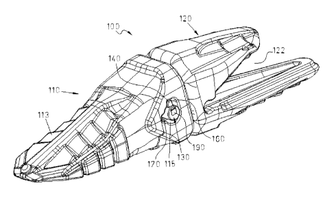
Figure 1 is a general perspective view of one embodiment of a wear assembly
including a wear element and a support element attached to each other by
means of a retaining pin;
Figure 2 is a general elevational view of the embodiment of the wear assembly
shown in figure 1;
Figure 3 is a perspective view of the wear element of the wear assembly shown
in figures 1 and 2;
Figure 4 is an elevational view of the wear element shown in figure 3;
Figure 5 is a perspective view of the support element of the wear assembly
shown in figures 1 and 2;
Figure 6 is an elevational view of the support element shown in figure 5;
Figure 7 is a perspective view of the one embodiment of a retaining pin;
Figure 8 is an elevational view of the retaining pin shown in figure 7; and
Figures 9 and 10 are diagrammatic views showing two different angular
positions
of the retaining pin within the wear assembly.
CA 02801528 2013-01-08
1 0
DETAILED DESCRIPTION OF EMBODIMENTS
The figures show a wear assembly indicated as a whole by reference numeral
100. The wear assembly 100 in the embodiment shown is a part of a machine or
equipment such as an excavator, bulldozer, angle-dozer, mechanical shovel,
shovel loader, road roller, a tamping machine, dragline bucket, and material
displacement machinery in general having parts subjected to wear and therefore
to be replaced periodically.
The wear assembly 100 in the embodiment shown comprises a wear element
110. The wear element 110 is shown in detail in figures 3 and 4 of the
drawings.
The wear element 110 as depicted corresponds to a finger, for example, a
finger
of an excavator bucket. The wear element 110 is made of a wear resistant
material and has a leading surface 113 that is suitable for operations
involving,
e.g. impact on the ground, dragging soil, scrubbing dust, etc.
The wear assembly 100 further comprises a support element 120. The support
element 120 is shown in detail in figures 5 and 6 of the drawings. The support
element 120 is typically an adapter that is coupled, e.g. to the excavator
bucket,
through a receiving portion 122 in the rear portion of the support element
120.
In use, both the wear element 110 and the support element 120 are attached to
each other by means of a retaining pin 130. The retaining pin 130 is shown in
detail in figures 7-8 of the drawings and it will be described further below.
Turning again to figures 5 and 6 of the drawings in which the support element
120 is shown, a nose 123 is defined in the front portion of the support
element
120. The nose 123 of the support element 120 is sized and shaped for being
suitably received into a nose receiving portion (not shown) formed inside the
wear element 110.
A first set of two mutually parallel longitudinal ridges 124 are provided in
the nose
123 in the support element 120. The longitudinal ridges 124 are formed
protruding from the leading surface 126 of the nose 123 as shown in figures 5
CA 02801528 2013-01-08
11
and 6. The longitudinal ridges 124 may be also formed protruding from a bottom
surface of the nose 123. The longitudinal ridges 124 are suitable for being
fitted
into the wear element 110 such that the support element 120 is prevented, or
at
least restrained, from being rotated relative to the wear element 110 when in
use.
A recess 128 is also formed in one side of an upper portion of a front wall
129 in
the nose 123 of the support element 120. The recess 128 is sized, arranged and
shaped for receiving a corresponding projection (not shown) formed within the
wear element 110.
The recess 128 together with the sets of longitudinal ridges 124 in the nose
123
of the support element 120 prevent, or at least restrain, the support element
120
from being rotated relative to the wear element 110 when in use.
Stabilization planes 127 are also defined both on the leading surface 126 and
at
the bottom portion of the nose 123. The stabilization planes 127 serve the
purpose of avoiding, or at least restraining, the relative longitudinal
movement of
the wear element 110 and the support element 120 when subjected to forces in
use. The configuration of the nose 123 with the longitudinal ridges 124, the
stabilization planes 127 and the recess 128 reduces stress on the retaining
pin
130 thus avoiding breaks or preventing the retaining pin 130 from being bent.
When the wear assembly 100 is in use, that is with the wear element 110 and
the
support element 120 assembled and attached to each other, see figures 1 and 2
of the drawings, the retaining pin 130 is fully inserted through the
respective
aligned openings 115, 125 of both the wear element 110 and the support
element 120. The configuration of the openings 115, 125 of the wear element
110 and the support element 120, respectively, allow for an easy insertion and
removal of the retaining pin 130 for attaching and detaching of the wear
element
110 and the support element 120 to each other.
Now referring to figures 7 and 8 of the drawings, the retaining pin 130
comprises
an elongated cylindrical body. The elongated cylindrical body of the retaining
pin
130 is preferably made of any suitable metal such as steel the length of which
is
CA 02801528 2013-01-08
12
substantially suitable for extending across both the wear element 110 and the
support element 120.
The elongated cylindrical body of the retaining pin 130 includes a first
retaining
protrusion 140 and a second retaining protrusion 150. The retaining
protrusions
140, 150 of the retaining pin 130 are formed with substantially flat surfaces.
The
retaining protrusions 140, 150 of the retaining pin 130 are angularly and
axially
spaced to each other as shown in figures 7 and 8. In the embodiment shown, the
relative angular displacement of the retaining protrusions 140, 150 of the
retaining pin 130 is 90 . Of course, other arrangements of the retaining
protrusions 140, 150 are possible. On the other hand, the relative axial
displacement of the retaining protrusions 140, 150 in the retaining pin 130 in
the
particular embodiment shown is reduced and may vary depending on the specific
design of the wear element 110 and the support element 120.
The recess 180 formed in the support wear element 120, as shown in figures 5
and 6 of the drawings, is a curved groove segment having substantially flat
walls.
Recess 180 is suitable for receiving the second retaining protrusion 150 of
the
retaining pin 130. In use second retaining protrusion 150 of the retaining pin
130
is allowed to slide along the recess 180 as the retaining pin 130 is rotated
for
locking or unlocking the retaining pin 130. The angular length of the curved
groove segment of the recess 180 determines the travel stroke of the second
retaining protrusion 150 of the retaining pin 130. The angular length of the
curved
groove segment of the recess 180 therefore defines the rotational displacement
of the retaining pin 130 from a first position, shown in figure 9, in which
the
retaining pin 130 can be moved freely axially for insertion into both the wear
element 110 and the support element 120, to a second position, shown in figure
10, in which the retaining pin 130 is rotated 90 (clockwise in the figures 9
and
10) such that the second retaining protrusion 150 is fitted between the recess
180 and an inner surface of the wear element 110 and therefore the retaining
pin
130 is prevented from being displaced axially relative to the wear element 110
and support element 120, and also prevented from being displaced radially as
it
will explained below.
CA 02801528 2013-01-08
13
In this embodiment, the second protrusion 150 of the retaining pin 130 is
formed
as a unitary piece together with the body of the retaining pin 130. The first
retaining protrusion 140 instead is resiliently mounted to the body of the
retaining
pin 130. In this particular embodiment, the first retaining protrusion 140 is
associated with an elastomer 200 fitted between the body of the retaining pin
130
and the first retaining protrusion 140. This allows the first retaining
protrusion 140
to be slightly moved along a line substantially perpendicular to the
longitudinal
axis of the body of the retaining pin 130.
The opening 115 of the wear element 110 has a first cavity 160 and a second
cavity 170 formed therein. The first cavity 160 and the second cavity 170 of
the
opening 115 formed in the wear element 110 are arranged at an angle of 90 to
each other as shown in the figures. The arrangement of the first and second
cavities 160, 170 may be other than the above mentioned arrangement at an
angle of 90 to each other as long as it corresponds with the angular
arrangement of the first and second retaining protrusions 140, 150 of the
retaining pin 130.
The particular arrangement of the first and second cavities 160, 170 allows
the
retaining pin 130 to be easily inserted into both the wear element 110 and the
support element 120 in the first angular position of the retaining pin 130 as
explained above. More specifically, the first and second retaining protrusions
140, 150 of the retaining pin 130 can be easily passed through said the first
and
second cavities 160, 170 of the opening 115 formed in the wear element 110.
The first cavity 160 is suitable for receiving the first retaining protrusion
140 of the
retaining pin 130 and the second cavity 170 is suitable for receiving the
second
retaining protrusion 150 of the retaining pin 130 in said first position.
As stated above, when the retaining pin 130 is in the first angular position,
it is
allowed to be inserted into the respective openings 115, 125 of the wear
element
and the support element 110, 120 with no significant force. Then, the
retaining
pin 130 should be fully inserted into the openings 115, 125 of the wear
element
110 and the support element 120. This occurs when the second retaining
protrusion 150 of the retaining pin 130 has been positioned beyond the side
wall
CA 02801528 2013-01-08
14
of the wear element 110 and received into the recess 180 formed in the support
element 120. In this situation in which the retaining pin 130 is fully
inserted into
the openings 115, 125 of the wear element 110 and with the retaining pin 130
is
in said first angular position, the retaining pin 130 has to be rotated, for
example
by using a tool having a head to be inserted into a tool receiving portion 190
formed at one or both ends of the retaining pin 130. The tool receiving
portion
190 may be hexagonal in shape for receiving a standard Allen-type tool for
driving the retaining pin 130 into rotation. Other types of tools, such as
square
head tool or even specially shaped head tools may alternatively used for
driving
the retaining pin 130 into rotation. Through the use of such tool (not shown)
the
retaining pin 130 can be rotated from said first position into the second
angular
position. When driving the retaining pin 130 into rotation through an angle of
about 90 the first retaining protrusion 140 of the retaining pin 130 leaves
the first
cavity 160 of the wear element 110 and becomes received into the second cavity
170 of the wear element 110. In this second angular position of the retaining
pin
130, the retaining pin 130 is locked against rotation. This is made possible
since
the first retaining protrusion 140 of the retaining pin 130 is biased radially
against
an inner surface of the first cavity 160 by means of the elastomer 200 as
described above. The hardness of the elastomer 200 will be chosen for both
allowing the snap fitting of the first retaining protrusion 140 of the
retaining pin
130 in the first cavity 160 of the wear element 110 and preventing the
retaining
pin 130 from being rotated relative to the wear element 110 and support
element
120. Locking of the retaining pin 130 is achieved due to the particular shape
and
size of the first cavity 160, smaller than the first retaining protrusion 140
of the
retaining pin 130. When the first retaining protrusion 140 of the retaining
pin 130
is fitted into the first cavity 160 of the wear element 110, the first
retaining
protrusion 140 is moved to the body of the retaining pin 130 and the elastomer
200 is pressed down. This results in that the retaining pin 130 becomes locked
against rotation in this second position.
Although only a number of particular embodiments and examples of a wear
assembly, retaining pin and a wear element have been disclosed herein, it will
be
understood by those skilled in the art that other alternative embodiments
and/or
uses and obvious modifications and equivalents thereof are possible. For
CA 02801528 2013-01-08
example, although the first retaining protrusion 140 has been disclosed as
being
resiliently mounted to the retaining pin 130, it would be possible, for
example,
that both retaining protrusions 140, 150 are formed integrally with the
retaining
pin 130. In this case the elastomer would be associated with the first cavity
160
of the wear element 110. The first cavity 160 would be provided with a biasing
portion adapted for radially biasing the second retaining protrusion 150 when
fitted in the first cavity 160 of the wear element 110. This similarly would
cause
the first retaining protrusion 140 of the retaining pin 130 to be snap fitted
in the
first cavity 160 of the wear element 110 resulting in that the retaining pin
130 is
locked against rotation relative to the wear element 110 and the support
element
120 when the retaining pin 130 is in said second position.
The claims cover all possible combinations of the particular embodiments
described. Reference signs related to drawings and placed in parentheses in a
claim are solely for attempting to increase the intelligibility of the claim,
and shall
not be construed as limiting the scope of protection. Thus, the scope of
protection should not be limited by the particular embodiments, but should be
determined only by a fair reading of the claims that follow.