Language selection

Search

Patent 2802020 Summary

Third-party information liability

Some of the information on this Web page has been provided by external sources. The Government of Canada is not responsible for the accuracy, reliability or currency of the information supplied by external sources. Users wishing to rely upon this information should consult directly with the source of the information. Content provided by external sources is not subject to official languages, privacy and accessibility requirements.

Claims and Abstract availability

Any discrepancies in the text and image of the Claims and Abstract are due to differing posting times. Text of the Claims and Abstract are posted:

  • At the time the application is open to public inspection;
  • At the time of issue of the patent (grant).
(12) Patent: (11) CA 2802020
(54) English Title: SUTURE THREAD
(54) French Title: FIL DE SUTURE
Status: Granted
Bibliographic Data
(51) International Patent Classification (IPC):
  • A61B 17/04 (2006.01)
  • A61B 17/06 (2006.01)
(72) Inventors :
  • LONGO, MAURIZIO (Italy)
  • SCACCHIA, FEDERICA (Italy)
  • LAZZARO, FRANCESCO (Italy)
  • CROVELLA, FELICIANO (Italy)
(73) Owners :
  • ASSUT EUROPE S.P.A. (Italy)
(71) Applicants :
  • ASSUT EUROPE S.P.A. (Italy)
(74) Agent: BERESKIN & PARR LLP/S.E.N.C.R.L.,S.R.L.
(74) Associate agent:
(45) Issued: 2015-03-24
(86) PCT Filing Date: 2011-07-07
(87) Open to Public Inspection: 2012-01-12
Examination requested: 2012-12-07
Availability of licence: N/A
(25) Language of filing: English

Patent Cooperation Treaty (PCT): Yes
(86) PCT Filing Number: PCT/IB2011/053016
(87) International Publication Number: WO2012/004758
(85) National Entry: 2012-12-07

(30) Application Priority Data:
Application No. Country/Territory Date
RM2010A000373 Italy 2010-07-08

Abstracts

English Abstract

A suture thread (1), comprising: - a thread-shaped main body (2) having spikes; and - a stopper cylinder (3) having a diameter enlarged with respect to the main body (2), which stopper cylinder (3) is arranged in correspondence of a longitudinal end (21) of the main body (2) to block said end in abutment against a tissue flap.


French Abstract

L'invention porte sur un fil de suture (1) comprenant : - un corps principal (2) en forme de fil ayant des pointes; et - un cylindre d'arrêt (3) ayant un diamètre élargi par rapport au corps principal (2), lequel cylindre d'arrêt (3) est disposé en correspondance avec une extrémité longitudinale (21) du corps principal (2) pour bloquer ladite extrémité en butée contre un lambeau de peau (Figure 1).

Claims

Note: Claims are shown in the official language in which they were submitted.

- 6 -
CLAIMS
1. A thread for suture or other sewing or stitching applications, comprising:
- an elongated main body; and
- a stopper having a section enlarged with respect to said main body and
arranged
at a longitudinal end of the latter to block said end in abutment against a
tissue
flap,
which stopper has a substantially cylindrical shape, with an axis (A) of the
cylinder
aligned with the direction of longitudinal development of said main body,
wherein said stopper has a thickness (S) along said cylinder axis (A)
comprised in a
range of about 1-2 mm,
wherein said stopper has a diameter (D) of about 4 mm,
and wherein said stopper and said main body are made of a material selected
from
a group comprising: glycolide polymer (PGA), copolymer of glycolide and
lactide
(PGLA), Poly(p-dioxanone) (PDO), copolymer of glycolide and epsilon-
caprolactone
(PGCL), and copolymer of Poly(l-lactide) and epsilon-caprolactone P(LA-CL).
2. The thread according to claim 1, having, at said main body, a plurality of
holding
spikes.
3. The thread according to claim 2, wherein said holding spikes are arranged
on said
main body in a way selected from the group consisting of: a monolateral way, a

plurilateral way and along a helical path.
4. The thread according to claim 2 or 3, wherein said holding spikes are
arranged on
said main body in a monodirectional or pluridirectional way.
5. The thread according to any one of claims 1 to 4, having a substantially
ring-
shaped or loop-like configuration.
6. The thread according to any one of claims 1 to 5, wherein said main body
comprises a pair of thread-shaped members.
7. The thread according to any one of claims 1 to 6, wherein said stopper is
fixed to
said main body by heat-welding.
8. The thread according to any one of claims 1 to 7, comprising a suture
needle
having a substantially straight or curved shape, arranged in correspondence of

another longitudinal end of said main body opposite to that associated with
said
stopper.

- 7 -
9. A reel, comprising a plurality of threads, each according to any one of
claims 1 to
8, which threads are arranged in a longitudinal sequence and removably
connected
at respective ends.
10. A method
for manufacturing a thread according to claim 2, comprising the
steps of:
- providing the main body of the thread having a plurality of holding
spikes;
- providing a mould having a shape corresponding to that of said stopper,
in the
form of a seat obtained in a plate, which plate rests on a board apt to be
heated;
- melting inside said mould a selected material for manufacturing said
stopper by
heating said board;
- heat-welding said main body to said stopper by inserting one end of said
main
body into said molten material and by subsequently cooling the assembly, this
latter step performed by removing said plate from said heated board; and
- separating said stopper from said plate.

Description

Note: Descriptions are shown in the official language in which they were submitted.


CA 02802020 2014-08-12
- 1 -
SUTURE THREAD
DESCRIPTION
The present invention refers to a thread, especially for use as a suture
= thread.
The operation of surgical nature most frequently performed in operating
room and outpatient clinic surgery is certainly that of suturing by thread.,In

spite of the frequency and the "historicity" of use of the suture threads, the

situ blocking modes of the ends thereof have not been optimized yet. In
particular, in order to secure one end of the thread against a portion of
biological tissue, the same thread is generally knotted on itself.
However, this blocking mode is intrinsically less than reliable as the knot,
over time, tends to come undone; this entails that, for each suturing
operation that proves necessary during surgery, the operator is forced to
make a high number of knots in sequence. Therefore, the entire suturing
operation carried out through the knotting technique requires a non-negligible

time significantly affecting the total length of the intervention, with the
associated consequences for the patient's wellbeing.
Therefore, the technical problem set and solved by the present invention is
that of providing a thread ¨ and in particular a suture thread ¨ allowing to
overcome the drawbacks mentioned above with reference to the known art.
Such a problem is solved by a thread according to the present invention.
Preferred features of the present invention are set forth in the dependent
claims thereof.
The present invention provides some relevant advantages. The main
advantage lies in the fact that the thread of the invention, by being equipped

with a stopper included in correspondence of a longitudinal end of the thread
itself, allows to reduce surgical times, eliminating the need to make plural
knots, and concomitantly improving the reliability of the sutures, since the
block is not subject to the drawback of coming undone. Moreover, by
eliminating the need to knot the main body of the thread on itself, the

CA 02802020 2012-12-07
WO 2012/004758 PCT/1B2011/053016
- 2 -
invention allows a greater variety of choice for the rigidity level of the
latter
and for the materials of which it is made, thereby allowing to meet any type
of suturing and surgery need.
Other advantages, features and operation steps of the present invention will
be made apparent in the following detailed description of some embodiments
thereof, given by way of example and not for limitative purposes. Reference
will be made to the figures of the annexed drawings, wherein:
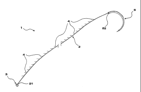
= Figure 1 shows a perspective view of a first preferred embodiment of the
lo suture thread according to the present invention;
= Figure 1A shows an enlarged view of a detail of the thread of Figure 1;
= Figure 2 shows a perspective view of a second preferred embodiment of
the suture thread according to the present invention;
= Figure 3 shows a perspective view of the suture thread of Figure 1, in
use during surgery; and
= Figures 4A, 4B and 4C show schematic front views illustrating three
respective steps of a preferred method for manufacturing the suture
thread of Figure 1.
Referring initially to Figures 1 and 1A, a suture thread according to a first
preferred embodiment of the invention is generally denoted by 1.
The thread 1 comprises first of all an elongated main body 2 having just a
thread-like shape. The main body 2 is preferably flexible and extends, in a
straight and extended configuration, along a longitudinal axis A.
On the main body 2 there are preferably provided holding spikes 4, i.e.
thread portions arranged obliquely with respect to the prevalent direction of
development of the main body 2 and apt, by virtue of said tilt, to engage the
tissue sutured by the thread itself so as to prevent the unthreading of the
latter along a given pull direction. Also the length and the thickness of the
spikes 4 can be selected depending on the selected cutting tilt.
The spikes 4 can be applied on the main body 2 in a monolateral way, as in
the depicted example, or in a plurilateral way. In both cases they can be
manufactured in a monodirectional way, as in the depicted example, or in a

CA 02802020 2012-12-07
WO 2012/004758 PCT/1B2011/053016
- 3 -
pluridirectional way, i.e. have a tilt along a single direction or along
plural
divergent directions. Moreover, the spikes 4 can be applied on the main body
2 even along a helical path or a spiral-like path.
In correspondence of a first longitudinal end 21 of the main body 2, the
thread 1 provides a stopper 3 having a section enlarged with respect to the
main body 2 itself.
Preferably, the stopper 3 has a substantially cylindrical shape, preferably
with an axis of the cylinder aligned with the axis A of the main body 2.
Always according to a preferred embodiment, the stopper 3 has a diameter
D of about 4 mm and a thickness S comprised in a range of about 1-2 mm.
During suturing, and as shown in Figure 3, the stopper 3, by virtue of its own

section enlarged with respect to the main body 2, can block the
corresponding longitudinal end 21 of the latter in abutment against a tissue
flap.
Main body 2 and stopper 3 can be made both of a same material and of
different materials, preferably of absorbable synthetic type.
In the present example, the stopper 3 and/or the main body 2 can be made
of a material selected from a group comprising: glycolide polymer (PGA),
copolymer of glycolide and lactide (PGLA), Poly(p-dioxanone) (PDO),
copolymer of glycolide and epsilon-caprolactone (PGCL), and copolymer of
Poly(1-lactide) and epsilon-caprolactone P(LA-CL).
The stopper 3 can be fixed to the main body 2 by heat-sealing.
In particular, a preferred embodiment schematically illustrated in Figures 4A,

4B and 4C envisages that the stopper 3 be made by melting of poly(p-
dioxanone) polymer in suitable moulds 60 of cylindrical shape of the above-
mentioned dimensions, preferably made in the form of openings shaped on a
metal plate 61 resting on a board 62 heated to about 130 C.
The connection between stopper 3 and main body 2 is then obtained by the
following steps:
- sealing of the "free" end 21 of the thread into the polymer paste still
molten in the mould 60 (the correct positioning of the thread at the center
of the cylindrical element can be guaranteed by a truing device positioned
on the plate 61) ¨ this step is schematically shown in Figure 4A;

CA 02802020 2012-12-07
WO 2012/004758 PCT/1B2011/053016
-4-
- removing the metal plate 61 from the heated board 62, in order to obtain
the cooling of the plate itself ¨ this step is schematically shown in Figure
4B; and
¨ separating the stopper from the metal plate ¨ this step is schematically
shown in Figure 4C.
Advantageously, the thread 1 is then prearranged, in correspondence of a
second longitudinal end 22 of the main body 2 opposite to that associated to
the stopper 3, with a suture needle 5 having a substantially straight or
curved
shape. Such a needle can be made of stainless steel (e.g. AISI 300 series or
lo AISI 400 series).
According to a second preferred embodiment shown in Figure 2, a suture
thread, denoted herein by 100, has a main body, denoted herein by 200,
which comprises a pair of thread-shaped members 201, 202, apt to define a
generally ring-shaped or loop-like structure of the thread itself.
The thread 100 comprises a stopper 3 analogous to that already described
above, and in this case as well it is prearranged with a suture needle, here
substantially straight, denoted by 50.
It will be understood that a plurality of suture threads, each as described
above with reference to Figures 1 and 2, may be provided in various calibers,
preferably comprised in the range USP 6/0 - 8, and in various lengths.
It will also be understood that a plurality of suture threads, each as
described
above with reference to Figures 1 and 2, may be provided in the form of a
reel. In particular, in that case threads will be arranged in a longitudinal
sequence and removably connected in correspondence of respective ends.
It will be understood that although the invention has been described with
specific reference to suture applications, it can advantageously be used for
any type of surgical need in which the use of a thread to be blocked in situ
be required.
Moreover, in a broader meaning the invention can find application also in a

CA 02802020 2012-12-07
WO 2012/004758 PCT/1B2011/053016
- 5 -
field different from the surgical one, for instance that of threads for
sewing,
especially in specialized fields like those of sewing or stitching technical
fabrics, such as for use in fishing, motorcycling, etc.
The present invention has been hereto described with reference to preferred
embodiments thereof. It is understood that other embodiments might exist,
all falling within the concept of the same invention, as defined by the
protective scope of the claims hereinafter.

Representative Drawing
A single figure which represents the drawing illustrating the invention.
Administrative Status

For a clearer understanding of the status of the application/patent presented on this page, the site Disclaimer , as well as the definitions for Patent , Administrative Status , Maintenance Fee  and Payment History  should be consulted.

Administrative Status

Title Date
Forecasted Issue Date 2015-03-24
(86) PCT Filing Date 2011-07-07
(87) PCT Publication Date 2012-01-12
(85) National Entry 2012-12-07
Examination Requested 2012-12-07
(45) Issued 2015-03-24

Abandonment History

There is no abandonment history.

Maintenance Fee

Last Payment of $263.14 was received on 2023-06-26


 Upcoming maintenance fee amounts

Description Date Amount
Next Payment if small entity fee 2024-07-08 $125.00
Next Payment if standard fee 2024-07-08 $347.00

Note : If the full payment has not been received on or before the date indicated, a further fee may be required which may be one of the following

  • the reinstatement fee;
  • the late payment fee; or
  • additional fee to reverse deemed expiry.

Patent fees are adjusted on the 1st of January every year. The amounts above are the current amounts if received by December 31 of the current year.
Please refer to the CIPO Patent Fees web page to see all current fee amounts.

Payment History

Fee Type Anniversary Year Due Date Amount Paid Paid Date
Request for Examination $800.00 2012-12-07
Application Fee $400.00 2012-12-07
Registration of a document - section 124 $100.00 2013-02-26
Maintenance Fee - Application - New Act 2 2013-07-08 $100.00 2013-06-19
Maintenance Fee - Application - New Act 3 2014-07-07 $100.00 2014-06-18
Final Fee $300.00 2014-12-01
Maintenance Fee - Patent - New Act 4 2015-07-07 $100.00 2015-06-29
Maintenance Fee - Patent - New Act 5 2016-07-07 $200.00 2016-06-28
Maintenance Fee - Patent - New Act 6 2017-07-07 $200.00 2017-07-03
Maintenance Fee - Patent - New Act 7 2018-07-09 $200.00 2018-06-25
Maintenance Fee - Patent - New Act 8 2019-07-08 $200.00 2019-06-24
Maintenance Fee - Patent - New Act 9 2020-07-07 $200.00 2020-06-29
Maintenance Fee - Patent - New Act 10 2021-07-07 $255.00 2021-06-28
Maintenance Fee - Patent - New Act 11 2022-07-07 $254.49 2022-06-27
Maintenance Fee - Patent - New Act 12 2023-07-07 $263.14 2023-06-26
Owners on Record

Note: Records showing the ownership history in alphabetical order.

Current Owners on Record
ASSUT EUROPE S.P.A.
Past Owners on Record
None
Past Owners that do not appear in the "Owners on Record" listing will appear in other documentation within the application.
Documents

To view selected files, please enter reCAPTCHA code :


To view images, click a link in the Document Description column. To download the documents, select one or more checkboxes in the first column and then click the "Download Selected in PDF format (Zip Archive)" or the "Download Selected as Single PDF" button.

List of published and non-published patent-specific documents on the CPD .

If you have any difficulty accessing content, you can call the Client Service Centre at 1-866-997-1936 or send them an e-mail at CIPO Client Service Centre.


Document
Description 
Date
(yyyy-mm-dd) 
Number of pages   Size of Image (KB) 
Claims 2012-12-08 2 64
Abstract 2012-12-07 1 52
Claims 2012-12-07 2 72
Drawings 2012-12-07 3 59
Description 2012-12-07 5 202
Representative Drawing 2012-12-07 1 6
Cover Page 2013-02-04 1 33
Representative Drawing 2015-02-24 1 6
Cover Page 2015-02-24 1 33
Claims 2014-08-12 2 65
Description 2014-08-12 5 200
Correspondence 2013-01-21 3 87
PCT 2012-12-07 19 729
Assignment 2012-12-07 5 154
Prosecution-Amendment 2012-12-07 3 103
PCT 2012-12-10 9 383
Correspondence 2013-02-01 2 75
Assignment 2013-02-26 3 88
Prosecution-Amendment 2014-02-13 3 140
Prosecution-Amendment 2014-08-12 15 607
Correspondence 2014-12-01 1 42