Note: Descriptions are shown in the official language in which they were submitted.
CA 02802073 2012-12-10
- 1 -
Pack for cigarettes and method and apparatus for
producing same
Description
The invention relates to a pack for cigarettes, having
at least one slide for accommodating pack contents, in
particular a cigarette group, and having a shell
enclosing the or each slide, wherein the shell has a
large-surface-area shell front side and a corresponding
shell rear side, which is located opposite, and shell
narrow sides, which connect the shell front side and
shell rear side to one another, and wherein adjacent
shell sides are connected to one another by upright
shell pack edges, according to the preamble of claim 1.
The invention also relates to a method and to an
apparatus for producing such a pack.
Numerous variants of packs of the "shell and slide"
type are known in practice. In addition to handling,
which is impractical in some cases, and the appearance,
which is not particularly innovative, complicated
production also poses a problem. Use is made here of
special machines, in particular production on existing
machines for hinge-lid packs is not possible.
Proceeding from this, it is an object of the invention
for packs of the type mentioned in the introduction to
be developed further, in particular in respect of a
pleasing design and simultaneous production capability
on known apparatuses.
CA 02802073 2012-12-10
- 2 -
In order to achieve this object, a pack having the
features of claim 1 is proposed. Accordingly, it is
provided that the shell pack edges are of rounded
and/or beveled design, and that at least two slides are
arranged in the shell, these slides being adapted to
the configuration of the rounded and/or beveled shell
pack edges, wherein the slides are of identical design.
The use of two or more identical slides within a shell
allows straightforward production of the slides. In
particular there is no need to produce a plurality of
different slides for fitting into a common shell. The
specially shaped pack edges give the pack a modern
design.
According to a preferred further development, it is
provided that the slides have a large-surface-area
slide front side and a corresponding slide rear side,
which is located opposite, and slide narrow sides,
which connect the slide front side and slide rear side
to one another, wherein adjacent slide sides are
connected to one another by upright slide pack edges,
and wherein the slide pack edges are adapted to the
rounded and/or beveled shell pack edges.
A further (also independent) special feature may
consist in that two slides are positioned within the
shell with their slide rear sides abutting, and in that
the slide pack edges are designed to be rounded and/or
beveled in the region of the slide front sides,
corresponding to the rounded and/or beveled shell pack
edges, and in that the slide pack edges are of right-
angled design in the region of the slide rear sides.
This makes it possible to fill a round-edge or beveled-
edge shell with two identical semi-round-edge or semi-
beveled-edge slides.
CA 02802073 2012-12-10
3 -
For better removal of the pack contents, it may be
provided that the slides, in the region of the slide
front side and of the slide rear side, have an upper-
side cutout or recess, wherein preferably the recesses
in the region of the slide front side and of the slide
rear side are of identical design.
A further special feature consists in measures for
limiting the displaceability of the slides in the
shell. For this purpose, it may be provided that the
slides can be moved only to a limited extent within the
shell on account of stops or connecting means, wherein
each slide has a plurality of stops or connecting means
which are arranged preferably on different sides and/or
at different heights in relation to a longitudinal axis
of the slide and which interact with corresponding
means on the inside of the shell such that the slides
can be moved to different extents within the shell.
This can preferably be achieved such that the slides,
in the region of opposite slide narrow sides, each have
a projecting lug, which are provided at different
heights, and that the shell, in the region of a shell
narrow side, has two corresponding lugs which, on
account of the slides being arranged in the shell with
their slide rear sides abutting, interact with the
different-height lugs of the slides, in order to limit
the movement capability of the slides within the shell
.to different extents for each slide.
In order to actuate the slides, it may be provided that
the shell has a shell base wall, wherein the shell base
wall and the respectively adjacent shell front side and
shell rear side have an opening, in particular a
sliding opening.
The shell preferably has a shell lid (shell upper
side), which is articulated in a pivotable manner on
the shell rear side, wherein the shell lid is connected
CA 02802073 2012-12-10
4 -
to regions of slide upper sides, in particular in each
case in the region between the two recesses such that,
when the shell lid is opened, the regions of the slide
upper sides which are connected to the shell lid, and
are bounded preferably by weakening lines, are removed
from the slides in order to expose the removal opening
for the pack contents in the region of the recesses.
The slides may have a closure flap (side inner flap)
which adjoins the slide upper sides and is fastened on
the inside of the slide front side, in particular by
adhesive bonding, and the closure flap, like the slide
front side, has a corresponding recess for the removal
opening.
The shell lid may have a flap which can be introduced
into a slot, formed in the region of the shell front
side, in order to close the shell lid.
A further special feature may consist in that the
slides, in the region of an upper side, have a removal
opening which, prior to the pack being opened for the
first time, is closed by a preferably common closure
means, in particular a closure tape, to form a sealed
pack.
A method according to the invention has the features of
claim 12. Accordingly, it is provided that in each case
at least two cigarette groups are pushed out of a
magazine for cigarettes and are wrapped parallel to one
another in an inner wrapper in order to form at least
two pack contents, and that, thereafter, the pack
contents are pushed into pockets of a correspondingly
multi-track folding turret, in which blanks for a slide
are located, and that the blanks are folded around the
respective pack contents on the folding turret and then
the slides are fed to a correspondingly multi-track
drying device, in particular a drying turret, and that
CA 02802073 2012-12-10
- 5 -
the slides are pushed one after the other out of the
multi-track drying device and fed one behind the other,
along a single-track transporting route, to a further,
in particular single-track, folding turret for the
shell, wherein the slides, during transportation, in
particular in the region of the single-track
transporting route, are rotated such that the slides
have their slide rear sides abutting in a manner
corresponding to the arrangement in the shell.
The blanks for the shell can be introduced into pockets
of the single-track folding turret, and therefore,
thereafter, two slides are introduced into the pocket
with their slide rear sides abutting, and folding of
the blank for the shell takes place.
An apparatus according to the invention has the
features of claim 14. Accordingly, provision is made
for subassemblies for multi-track production of the
slides, in particular a two-track folding turret and at
least one adjoining two-track drying turret, and for
following subassemblies for a single-track production
of the shell, in particular a single-track folding
turret and at least one adjoining drying turret.
Further details of the invention can be gathered from
the dependent claims, from the rest of the description
and from the drawings.
Preferred exemplary embodiments of the invention will
be explained hereinbelow with reference to the drawing,
in which:
Fig. 1 shows a blank for an inner wrapper of a
cigarette group,
Fig. 2 shows a blank for a slide,
CA 02802073 2012-12-10
- 6 -
Fig. 3 shows a blank for a shell,
Fig. 4 shows a three-dimensional illustration of
pack contents,
Fig. 5 shows a three-dimensional illustration of a
slide with pack contents,
Fig. 6 shows a three-dimensional illustration of two
slides arranged as in a shell,
Fig. 7 shows a three-dimensional illustration of a
closed pack,
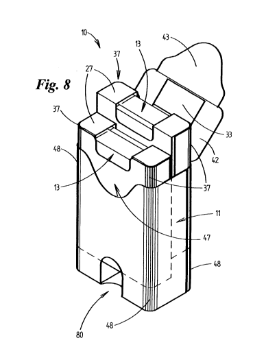
Fig. 8 shows a pack according to fig. 7, this time
in an open position,
Fig. 9 shows a second exemplary embodiment of a
blank for a shell,
Fig. 10 shows a second exemplary embodiment of a
blank for a slide,
Fig. 11 shows a three-dimensional illustration of two
slides made from a blank according to fig. 10
and arranged as in a shell,
Fig. 12 shows a three-dimensional illustration of a
closed pack made from a blank according to
fig. 9,
Fig. 13 shows a pack according to fig. 12, this time
in an open position,
Fig. 14 shows a horizontal section through a pack
according to fig. 12,
CA 02802073 2012-12-10
7 -
Fig. 15 shows an enlarged illustration of a detail of
the pack according to fig. 13,
Fig. 16 shows a three-dimensional illustration of two
slides arranged as in a shell and with a
special closure,
Fig. 17 shows an open pack with slides with a special
closure,
Fig. 18 shows a schematic illustration of the
production of packs according to the
invention,
Fig. 19 shows, on an enlarged scale, a detail of the
schematic illustration according to fig. 18,
and
Fig. 20 shows, on an enlarged scale, a further detail
of the schematic illustration according to
fig. 18.
The invention will be explained hereinbelow with
reference to a pack 10 of the shell-and-slide type.
Essential constituent parts of this type of pack are a
sleeve 11, as the outer pack, and slides 12, which can
be displaced in the sleeve, for accommodating pack
contents.
A first special feature consists, in the present case,
in two slides 12 being positioned within a common shell
11. Each slide 12 contains pack contents 13. The pack
contents 13 are constituted in each case by a cigarette
group which is arranged in the form of a cigarette
block and is wrapped in an inner liner 14.
The slides 12 are of identical design and are
positioned back to back in the shell 11.
CA 02802073 2012-12-10
8 -
A blank for the inner liner 14 according to fig. 1 is
folded around the cigarette block or the cigarette
group along folding lines 15. The starting point here
is an inner-liner base side 16, which is arranged in
the region of an end side of the cigarette group and
which is adjoined on either side by an inner-liner
front side 17 and inner-liner rear side 18, which each
butt against corresponding surfaces of the cigarette
group. The inner-liner front side 17 and the inner-
liner rear side 18 are each adjoined by folding flaps
for the inner-liner upper side 19. Folding flaps for
inner-liner narrow sides 20 are arranged on either side
of the inner-liner base side 16, inner-liner front side
17, inner-liner rear side 18 and inner-liner upper side
19.
Starting from the inner-liner base side 16, the inner
liner 14 is wrapped in a U-shaped manner around the
cigarette group and is closed in the region of the
inner-liner upper side 19 by the corresponding folding
flaps being folded in the manner of an envelope. The
corresponding folding flaps of the inner liner 14
overlap one another in the region of the inner-liner
narrow sides 20.
In order to allow access to the pack contents or the
cigarette group, material weakenings 21 are provided in
the inner liner 14. The material weakening 21 bounds a
so-called tear-off flap 22, which is formed
continuously in each case in the region of the inner-
liner upper side 19 and of the inner-liner front side
17, on the one hand, and of the inner-liner rear side
18, on the other hand. The two tear-off flaps 22 are
arranged on the periphery of the inner liner 14 such
that, once the inner liner 14 has been folded around
the cigarette group, they are positioned in the region
of the inner-liner upper side 19 and of the two
CA 02802073 2012-12-10
9 -
adjacent side surfaces. By virtue of the tear-off flaps
22 being gripped and separated off, an opening is
created in the inner liner 14, and this opening allows
the consumer to remove individual cigarettes.
Fig. 2 shows a blank 23 for the slides 12. The blank 23
is divided up into portions for various regions of a
slide 12. Arranged to follow one after the other in the
longitudinal direction are a slide front side 24, a
slide base side 25, a slide rear side 26, a slide upper
side 27 and a slide inner flap 28. Slide corner flaps
29 are arranged on either side of the slide base side
25 and of the slide upper side 27. Slide side flaps 30
are arranged on either side of the slide front side 24
and of the slide rear side 26, in order to form slide
narrow sides 31. The individual regions of the blank 23
are separated off from one another, in turn, by folding
lines 15.
Cutouts 32 are arranged in the region of the slide
front side 24, of the slide rear side 26 and of the
slide inner flap 28, in a manner corresponding to the
position of the tear-off flaps 22 in the inner liner
14, in order to facilitate access to the pack contents
13. In the region of the slide upper side 27, between
the two adjacent cutouts 32, a region 33 is bounded by
material weakenings 34 and can be severed from the
slide upper side 25 in order to create a removal
opening.
Furthermore, the blank 13 has spots of glue 35 for the
slide corner flaps 29 and also continuous glue strips
36, in the region of the slide side flaps 30, in order
for the latter to be glued.
A further special feature of the slides 12 consists in
that upright slide pack edges 37 on either side of the
slide front side 24 are designed as round edges. For
CA 02802073 2012-12-10
- 10 -
this purpose, corresponding material weakenings are
provided in the blank 23 in the region of the slide
front side 24. The two upright pack edges on either
side of the slide rear side 26 are designed as standard
right-angled pack edges.
The folded shell 12 according to fig. 5 is formed such
that the slide side flaps 30 overlap one another, and
are adhesively bonded to one another by the glue strips
36, in the region of the slide narrow sides 31. The
slide inner flap 28 is folded against the inside of the
slide front side 24 and fastened there by the spots of
glue 35 on the upper periphery of the slide front side
24. The slide corner flaps 29 are secured in position
by the spots of glue in the region of the slide base
side 25 and of the slide upper side 27.
Fig. 3 shows a blank 38 for the shell 11. As in the
case of the blank 23 for the slide 12, a shell front
side 39, a shell base side 40, a shell rear side 41 and
a shell upper side 42 are arranged one after the other
in the blank 38. These regions are separated from one
another by folding lines 15. The shell upper side 42 is
also adjoined by a shell insertion flap 43. Shell side
flaps 44, for forming shell narrow sides 45, are
arranged to the sides of the shell front side 39 and of
the shell rear side 41. Adjacent to the shell base side
40, shell corner flaps 46 are arranged on the shell
side flaps 44 of the shell rear side 41.
Once again, glue strips 36 are provided in the region
of the shell side flaps 44 of the shell front side 39.
The shell base side 40 is provided with spots of glue
in order to fasten the shell corner flaps 46.
In order for it to be possible to move the slides 12 in
the shell 11, the shell blank 38 also has two elongate
openings 80, as sliding openings. The openings 80 are
CA 02802073 2012-12-10
- 11 -
each arranged in the region of the shell front side 39
and of the shell rear side 41 and extend into the
region of the shell base side 40. This allows the
slides 12 to be gripped on the underside, and at the
sides, by the consumer and to be pushed upwards in
order for cigarettes to be removed. The openings 80
have different extents, starting from the shell base
side 40, along the shell front side 39 and the shell
rear side 41 in the direction of the shell upper side
42. This means that the slides 12 can be pushed out of
the shell 11 to different extents. In the present case,
the opening 80 in the region of the shell rear side 41
is longer than the opening 80 in the region of the
shell front side 39, and therefore the slide 12 which
is at the rear in fig. 8 can be pushed out of the shell
11 to a further extent than the front slide 12. This
facilitates removal of the pack contents 13 from the
rear slide 12, which would otherwise be imputed by the
shell upper side 42.
A contoured cutout 47 is provided in the region of the
upper periphery of the shell front side 39. In the
region of the cutout 47, the lower periphery of the
shell insertion flap 43 is pushed behind the shell
front side 39 in order to close the shell (fig. 7).
The shell has rounded shell pack edges 48 both on
either side of the shell front side 39 and on either
side of the shell rear side 41.
Precisely two slides 12 are accommodated within the
shell 11. By virtue of the slide 12 being arranged with
the slide rear side 26 of one slide 12 against the
slide rear side 26 of another slide 12, the slide pack
edges 37 of rounded cross section are positioned in the
correspondingly rounded pack edges 48 of the shell 11.
Accordingly, the right-angled pack edges in the region
CA 02802073 2012-12-10
- 12 -
of the slide rear sides 26 are directed toward one
another.
The regions 33 in the slide upper sides 27 which are
bounded by material weakening 34 can be adhesively
bonded to the inside of the shell upper side 40, and
therefore, when the lid of the shell 11 or the shell
upper side 40 is opened for the first time, the regions
33 are severed from the slide upper sides 27 (fig. 8).
Even if the pack edges above were designed as round
edges, it is also conceivable, of course, for the
corresponding pack edges also to be designed as beveled
edges or as some other kind of special edge.
Figs. 9 to 15 show a second embodiment of the
invention. The inner liner 14 here corresponds to the
blank 14 which is shown in the first exemplary
embodiment according to figs. 1 to 8.
A blank 49 for the shell 11 according to fig. 9 differs
from the blank 38 according to fig. 3 in a number of
aspects. First of all, the shell insertion flap 43 is
designed to be shorter. Correspondingly, rather than
having a peripheral cutout 47, the shell front side 39
has an incision 50 which is spaced apart from the upper
periphery of the shell front side. The lower end of the
shell insertion flap 43 is inserted into this incision
50 in order to close the pack 10 (fig. 12).
A further special feature consists in means for
limiting the displaceability of the slides 12 within
the shell 11.
In the first instance, the slides 12, in the region of
the slide side flaps 30, each have a lug 51, 52 formed
by punching. The lugs 51, 52 can be folded about a
folding line 53, as shown in fig. 11, such that free
CA 02802073 2012-12-10
- 13 -
peripheries of the lugs 51, 52 are oriented in the
direction of the slide upper side 27. It is important
here for the lugs 51, 52 in the region of the opposite
slide narrow sides 31 to be arranged at different
heights in relation to the longitudinal axis of the
shell 11. With the shells 11 being arranged "back to
back", this results in the lugs 51, 52 being positioned
as shown in fig. 11, that is to say in the region of
adjacent slide narrow sides 31, but at different
heights.
The shell 11 according to fig. 9 has corresponding
means, that is to say two lugs 54, which are arranged
on the upper periphery of a slide side flap 30 and can
be folded about a common folding line 55 such that they
have their free periphery oriented in the direction of
the shell base side 40. In contrast to the lugs 51, 52
on the slides 12, however, the lugs 54 are folded over
in the direction of the interior of the shell 11, and
therefore they come into contact with the lugs 51, 52,
which are arranged on the outside of the slides 12, as
soon as the slides 12 are pushed upwards to a
corresponding extent within the shell 11. The folded
arrangement of the lugs 51, 52, 54 in relation to one
another means that these lugs interlock. In addition,
the movement of the slides 12 within the shell 11 is
braked by the friction of the lugs 51, 52 and 54
against one another before the design-specific end
position of the slides 12 has been reached.
Arranging the lugs 51, 52 at different heights means
that the two slides 12 can be pushed out of the shell
11 to different extents, as fig. 13 shows. The
identical design of the slides 12 is nevertheless
maintained.
The illustration according to fig. 14 shows that the
pack contents 13 in the two slides 12 need not have the
CA 02802073 2012-12-10
- 14 -
same quantity of cigarettes. The solution shown is one
in which one pack contents has only twelve cigarettes
and the other has thirteen cigarettes. This allows for
the filling with twenty-five cigarettes which is
preferred in some countries. Of course, it is also
conceivable to have other cigarette formations, for
example with more or fewer rows of cigarettes.
Fig. 16 shows a variant in which the cutouts 32 of the
slides 12 are concealed on the upper side in each case
by a closure tape 56. The closure tape 56 extends in
each case over the two slides 12 which are arranged
back to back. The closure tape 56 is dimensioned such
that it completely covers the openings formed in the
slides 12 and projects laterally beyond the openings,
this therefore ensuring a secure connection, for
example adhesive bonding, to the slides 12.
It is also conceivable to design the closure of the
openings such that the slides 12 are designed as sealed
packs. In this case, it is also possible to dispense
with the inner liner 14.
In order to open the closure tape 56, a respective grip
tab 57 is provided at a free periphery of the tape 56
in the region of the slide front side 24 and of the
slide rear side 26. This allows the closure tape to be
opened irrespective of the orientation of the slide 12
in the shell 11. In addition, the two slides 12
required may be identical.
In the case of the solution which is shown in fig. 16,
it is also possible to dispense with the region 33 on
the slide upper side 27. However, it is also
conceivable to provide the region 33 and to connect the
same to the closure tape 56, and therefore this region
33 is severed from the slides 12 when the respective
closure tape 56 is opened for the first time.
CA 02802073 2012-12-10
- 15 -
Fig. 18 shows a schematic illustration of an apparatus
and a method sequence for producing packs 10 according
to figs. 1 to 17.
Starting from a cigarette magazine 58, production takes
place, in the first instance, on two tracks
corresponding to the number of slides 12 in a shell 11.
The cigarettes are supplied in upright shafts and are
pushed off out of the shafts of the cigarette magazine
58 into a two-track cigarette turret 59.
Once a cigarette turret 59 has rotated through 180 ,
the cigarette groups are pushed out of the cigarette
turret 59 and transported along a horizontal two-track
conveying route in the direction of the arrow 60.
Allowance can be made for the formation of cigarette
groups with different numbers of cigarettes as the
latter are pushed out of the cigarette magazine 58.
In the next operating step, the cigarette groups are
wrapped in the inner liner 14. This takes place in a
wrapping station 61, which is likewise of two-track
design. The blanks for the inner liner 14 are drawn off
as a continuous material web from two reels and the
blanks are then separated. Thereafter, the cigarette
groups are moved against the inner-liner blanks 14
supplied and wrapped therein in a known manner.
Following wrapping in the inner liner 14, the resulting
pack contents 13 are transported along a further
horizontal transporting route in the direction of arrow
62.
Next, the pack contents 13 are introduced in pairs into
correspondingly arranged pockets 63 of a two-track
folding turret 64. Beforehand, however, blanks 23 for
the slides 12 are removed from a blank magazine 65,
preferably above the folding turret 64, and introduced
CA 02802073 2012-12-10
- 16 -
into the pockets 63 and pre-folded. Once the pack
contents 13 have been fed, the slides 12 are completed
in a known manner. Once the slides 12 have been pushed
out of the folding turret 64, folding of the slide side
flaps 30 continues as the slides 12 are transported
along a further horizontal transporting route along
arrow 66.
In order for glue connections to set, the slides 12 are
pushed into a two-track drying wheel 67. As the slides
12 circulate on the drying wheel 67, it is possible for
at least some glue connections to set. Thereafter, the
slides 12 are pushed one after the other out of the
drying wheel 67 and are transported one after the other
along a single-track conveying route in the direction
of the arrow 68. When the slides 12 are pushed out of
the drying wheel 67, it should be ensured that the
slides 12 with possibly different contents are pushed
out alternately. This ensures that each pack 10
subsequently contains the same number of cigarettes.
As they are transported further in the region of the
single-track conveying route, the slides 12 are
accumulated and transported further in the direction of
arrow 69. The accumulated slides 12 are then pushed in
groups into a further drying wheel 70, and setting of
the glue can therefore be brought to an end.
Thereafter, the slides 12 are conveyed along an
adjoining single-track conveying route in the direction
of arrow 71.
At the end of the single-track conveying route, the
slides 12, once again, are accumulated and transported
away in pairs in the direction of an adjoining
horizontal conveying route following arrow 72.
Corresponding to the manner in which production has
taken place up until this point, the pairs of slides 12
CA 02802073 2012-12-10
- 17 -
are each located with the slide front side 24 against a
slide rear side 26 of another slide 12. In order for
the slides 12 to pass into the correct "back to back"
position relative to one another, the slides 12 have to
be rotated. This takes place during further
transportation along the single-track horizontal
transporting route. For this purpose, use can be made
of the prior-art means such as, for example, pack
diverters.
In the next step, the slides 12 are packed into a shell
11. For this purpose, use is made of a further folding
turret 73, which is assigned a blank magazine 74 with
blanks 38 for the shells 11. As in the case of the
folding turret 64, the blanks 38, in the first
instance, are removed from the blank magazine 74 and
introduced into pockets 75 of the folding turret 73 and
pre-folded. Thereafter, a pair of slides 12 is moved
into the pocket 75 and folding of the blank 38 is
completed, as on the first folding turret 64 for the
slides 12.
Once the shell 11 has been brought together with two
slides 12, the packs 10 which have been completed in
this way are fed to a single-track drying wheel 76. The
drying wheel 76 is adjoined by a relatively small
transfer turret 77, which transfers the packs 10 to a
horizontal conveying route in the direction of arrow
78. The packs 10 are then, finally, passed on, in
groups, into a further drying wheel 79.
CA 02802073 2012-12-10
- 18 -
List of designations
10 Pack 42 Shell upper side
11 Shell 43 Shell insertion flap
12 Slides 44 Shell side flaps
13 Pack contents 45 Shell narrow sides
14 Inner liner 46 Shell corner flaps
Folding lines 47 Cutout
16 Inner-liner base side 48 Shell pack edges
17 Inner-liner front side 49 Shell blank
18 Inner-liner rear side 50 Incision
19 Inner-liner upper side 51 lug
Inner-liner narrow 52 lug
side
21 Material weakening 53 Folding line
22 Tear-off flap 54 lug
23 Slide blank 55 Folding line
24 Slide front side 56 Closure tape
Slide base side 57 Grip tab
26 Slide rear side 58 Cigarette magazine
27 Slide upper side 59 Cigarette turret
28 Slide inner flap 60 arrow
29 Slide corner flaps 61 Wrapping station
Slide side flaps 62 Arrow
31 Slide narrow sides 63 pocket
32 Cutout 64 Folding turret
33 Region 65 Blank magazine
34 Material weakening 66 Arrow
Spots of glue 67 Drying wheel
36 Glue strips 68 arrow
37 Slide pack edges 69 Arrow
38 Shell blank 70 Drying wheel
39 Shell front side 71 arrow
Shell base side 72 arrow
41 Shell rear side 73 Folding turret
CA 02802073 2012-12-10
- 19 -
74 Blank magazine
75 Pockets
76 Drying wheel
77 Transfer turret
78 Arrow
79 Drying wheel
80 Opening