Note: Descriptions are shown in the official language in which they were submitted.
HANDLE FOR A PLASTIC BOTTLE
TECHNICAL FIELD
The present invention relates to a handle for a plastic bottle.
BACKGROUND TECHNOLOGY
Conventionally, a handle like that described for example in JP 3754-000012 are
known as this kind
of handle. This handle has a frontal head part for the neck part of the
bottle, an insertion part for attachment
for the groove at the lower part of the bottle body, and a connecting part
that connects the frontal head part
and the insertion part for attachment. A space where the hand can be inserted
is provided between the
connecting part and the bottle body, and this connecting part is configured
such that it functions as the
user's handle.
SUMMARY OF THE INVENTION
Problems that the Invention Attempts to Solve
However, in the case of the handle in JP 3754-000012, the connecting part for
the handle takes a
wide space in the state where it is attached to the bottle, and the storage
for the pockets of a refrigerator,
etc. is poor.
In addition, since the insertion part for attachment of the handle is hung in
the groove of the bottle
body at the time of attachment, it is not possible to attach it well owing to
the design (shape, size) of this
groove, and stably supporting the bottle is difficult.
1
CA 2802267 2019-03-29
CA 02802267 2013-01-21
In particular, such an attachment method is ill suited for lightweight
bottles. It has reached the
point where a bottle body with lighter weight is deformed flexibly and
readily. Owing to this, when the
insertion part for attachment of the handle is hung in groove of the bottle
body, there is a chance that
the bottle body may be deformed. Not only that, but also when the bottle is
tilted when the contents are
being poured after attachment, the bottle body is subject to the pressure from
the insertion part for
attachment at only the groove, so the bottle body is deformed with this as the
starting point, and there is
a chance that the support of the bottle may become unstable.
The present invention was created in view of the above background, and takes
as its purpose
the provision of a handle that can ensure the storability to a pocket, etc. of
a refrigerator even in a state
where it is attached to a bottle, and that in addition can provide stable
support even for a bottle whose
weight is to be lightened.
Means for Solving the Problems
In order to achieve the above-mentioned purposes, the inventive handle is
provided with a neck
supporting part that is composed in such a manner that it mates with the neck
of a bottle made of
plastic and supports this, a bottom supporting part that is composed in such a
manner that it receives
the bottom of the bottle and supports the bottom portion of said bottle, and a
gripping part that connects
.. the neck supporting part and bottom supporting part. The neck supporting
part has a first engagement
part and a second engagement part with which the neck can engage and
disengage. The gripping part
exists as an extension in the vertical direction in such a manner that it runs
along the body of the bottle
in the event that the neck is engaged with the first engagement part, and
exists as an extension that is
slanted relative to the vertical direction in such a manner that it draws
apart from the bottle in the event
that the neck is engaged with the above-mentioned second engagement part.
According to the present invention, if the neck of the bottle is engaged in
the first engagement
part when the bottle is to be stored in the pocket of the refrigerator, etc.,
it is possible to make the
gripping part approach the body of the bottle. Owing to this, the gripping
part does not occupy a wide
space, so it is possible to ensure the storability in this kind of bottle. On
the other hand, if the neck of
the bottle is engaged in the second engagement part when the bottle is
handled, such as lifting the
bottle and pouring the contents of the bottle, it is possible to form a larger
space between the upper part
of the inclined gripping part and the bottle than in the engaged state with
the first engagement part.
2
CA 02802267 2013-01-21
,
Owing to this, the user can insert his hand into this space and hold the
gripping part, and easy handling
of the bottle is enabled.
In addition, since the support position of the handle relative to the bottle
becomes the up-down
position of the bottle that is the neck part and the lower portion of the
bottle, the movement when tilting
the bottle and pouring out its contents is stable. Moreover, it is configured
such that the support of the
lower portion of the bottle can be performed by receiving the bottom of the
bottle. Owing to this, it is not
greatly affected by the design of the bottle body, and it is possible to
support the bottle stably, even in
the case of a lightweight, flexible bottle.
Preferably, the bottom supporting part supports in such a manner that it
envelopes the lower
portion of the bottle.
According to this configuration, since the holdability (controllability) of
the lower portion of the
bottle is improved, it is possible to support the bottle more stably. As the
mode for supporting the bottle
in such a manner that the lower portion of the bottle is enveloped, one can
cite a mode wherein the
bottom supporting part faces on the entire region of the of the lower portion
of the bottle, and in addition
a mode in which it faces over the entire periphery on at least one region of
the lower portion of the
bottle.
More preferably, the bottom supporting part may have a first side plate part
that receives the
bottom of the bottle, a second side plate part that extends upwards from the
bottom plate part towards
the gripping part, and a pair of third side plate parts that connect the first
side plate part and the second
side plate part in such a manner that they envelope the lower portion of the
bottle in addition to the first
side plate part and the second side plate part.
According to this configuration, it is possible to support the bottle in such
a manner that the
lower portion of the bottle is enveloped by the first to third side plate
parts. The pair of third side plate
parts is formed such that they are opposed to one another, but the positions
thereof in the up-down
direction may be the same or it may be different.
More preferably, the third side plate part is positioned upwards from the
bottom plate part.
3
CA 02802267 2013-01-21
According to this configuration, compared to a case in which the third side
plate part is formed
in such a manner that it stands erect slightly from the bottom plate part,
when for example the bottle is
tilted, the third plate part ends up supporting a spot that is the upper part
of the lower portion of the
bottle. Therefore, it is possible to further improve the holdability of the
lower portion of the bottle.
More preferably, projecting parts that slot into the groove of the bottle may
be formed on at
least one of the first side plate part and the second side plate part.
According to this configuration, the lower portion of the bottle can escape
the force it receives
from the first or second side plate part when the bottle is for example tilted
through the projecting parts
on the groove, which realizes the effect of reinforcement of the bottle, so it
is possible to inhibit the
deformation of the lower portion of the bottle. IN addition, the holdability
of the bottle is also improved. It
is still more preferable that the projecting parts are position higher than
the third side plate part.
Preferably, a leg for placing said bottle horizontally may be formed on the
outer surface of the
first side plate part.
According to this configuration, since it is possible to place the handle and
a bottle with a
handle attached horizontally, it is possible to improve the ease with which
these are handled. In addition,
it is possible to utilize efficiently the first side plate part for supporting
the lower portion of the bottle, and
to provide a leg.
More preferably, in the event that the neck is engaged with the first
engagement part, the leg
may be formed in such a manner that it does not protrude more to the outside
than the gripping part.
According to this configuration, in the event that the bottle is stored in a
state in which it is
placed vertically in the pocket, etc. of a refrigerator, the leg for
horizontal placement does not become a
hindrance. Therefore, the storability is not impaired, and it can be provided
for uses involving both
vertical placement and horizontal placement.
According to another preferable mode of the present invention, the bottom
supporting part may
have a bottom plate part that receives the bottom of the bottle, a tubular
peripheral wall part that
extends upwards from the bottom plate part, and an opening is formed
intermittently in the peripheral
direction for the peripheral wall part.
4
CA 02802267 2013-01-21
According to this configuration, it is possible to support in such a manner
that the lower portion
of the bottle is enveloped, even while providing for lighter weight of the
bottom supporting part.
Preferably, the first engagement part is positioned on the gripping part side,
and moreover the
second engagement part is positioned on the side opposed to the gripping part
in such a manner that it
is opposed to the first engagement part, and the neck supporting part may have
an opening part in the
space between the first engagement part and the second engagement part that
can pass through in the
horizontal direction when the neck engages with the first engagement part or
engages the second
engagement part.
According to this configuration, since the first engagement part and second
engagement part
are positioned in such a manner that they are opposed to one another, the
movement when changing
the engaged state is easier. In addition, it is possible to employ a common
opening part and to move to
any of the engaged states.
Preferably, the gripping part may have a changed part wherein the inner
surface of the upper
side part has added changes compared to the inner surface of the lower side
part.
According to this configuration, it is possible to make the user aware about
gripping the upper
side portion of the gripping part. In addition to the degree that changes are
added, the rigidity thereof
can also be increased.
More preferably, the changed part may be formed by at least one of the step
parts.
According to this configuration, since it becomes a device to prevent slipping
when the user
grips it, it is possible to improve the portability and the ease of pouring.
Preferably, the lower end part of the gripping part may have a rigidity that
is lower than that of
at least one part of the upper end part thereof, in such a manner that the
gripping part bends with said
lower end part of said gripping part as the fulcrum when there is a change
between a state in which the
neck is engaged in the first engagement part and a state in which it is
engaged in the second
engagement part.
5
According to this configuration, the movability of the gripping part when the
engagement state is changed
can be performed smoothly. In addition, since the lower end part of the
gripping part is used as the fulcrum of the
bending, even if the angle of inclination of the gripping part when the neck
is engaged in the second engagement
part is small, it is possible to increase as much as possible the space that
is formed between the upper part of the
gripping part and the bottle.
Preferably, the gripping part may have a pair of flange parts that extend
towards the outside in opposed
to one another, between but not including the upper end part and lower end
part of said gripping part.
According to this configuration, since the sectional secondary moment becomes
larger at the up-down
intermediate portion of the gripping part, it is possible to increase the
rigidity of the up-down intermediate portion
of the gripping part, and the ease of handling of the handle as experienced by
the user (portability and ease of
pouring) improves. On the other hand, since the rigidity of the lower end part
of the gripping part becomes lower,
it is bent more easily with this lower end part as the fulcrum, and it is
possible perform smoothly the movability of
the above-described gripping part.
Preferably, the upper end part of the gripping part may have a curved wall
part that is curved upwards.
According to this configuration, it is possible to form a finger rest between
the curved wall part and the
upper part of the bottle. Owing to this, naturally in the event that the neck
is engaged in the second engagement
part, but even in the event that it is engaged in the first engagement part,
it becomes possible to improve the
portability of a handle that employs the space for a finger rest.
According to an aspect of the present invention there is provided a handle for
a bottle with a neck, a
bottom, and a body, the handle comprising:
a neck supporting part that mates with and supports the neck of the bottle,
wherein the neck
supporting part comprises a first engagement part and a second engagement
part;
a bottom supporting part that receives and supports the bottom of the bottle,
wherein the bottom
supporting part comprises:
a bottom plate part that receives the bottom of the bottle,
a first inverted U-shaped side plate part having ends and an apex, wherein the
ends of
the first inverted U-shaped side plate part connect to and extend upward from
the bottom plate part, wherein the
apex of the first inverted U-shaped side plate part connects to a gripping
part,
6
CA 2802267 2019-03-29
a second inverted U-shaped side plate part having ends and an apex, wherein
the ends
of the second inverted U-shaped side plate part connect to and extend upward
from the bottom plate part on a
side opposed to the gripping part, wherein the apex of the second inverted U-
shaped side plate is in a free state,
and
a pair of third side plate parts that connect the first inverted U-shaped side
plate part
and the second inverted U-shaped side plate part in such a manner that they
envelope a lower portion of the
bottle in addition to the first inverted U-shaped side plate part and the
second inverted U-shaped side plate part;
the gripping part connects the neck supporting part and the bottom supporting
part;
a connecting part that connects the first engagement part with the second
engagement part;
an opening part disposed opposite the connecting part in a space between the
first engagement
part and the second engagement part;
a first configuration with the gripping part extending in a substantially
vertical direction along the
body of the bottle with the neck engaged with the first engagement part; and
a second configuration with the gripping part extending in a substantially
slanted direction
relative to the substantially vertical direction so as to draw apart from the
bottle with the neck engaged with the
second engagement part.
BRIEF DESCRIPTION OF THE FIGURES
Figure 1 is a figure showing a state in which the handle for the Embodiment 1
is attached to the bottle, and a
figure in which the neck of the bottle is engaged with the first engagement
part.
Figure 2 is a figure showing a state in which the handle for the Embodiment 1
is attached to the bottle, and a
figure in which the neck of the bottle is engaged with the second engagement
part.
Figure 3 is an oblique view showing the handle for the Embodiment 1.
6a
CA 2802267 2019-03-29
CA 02802267 2013-01-21
Figure 4 is a right side figure of Figure 1.
Figure 5 is a right left figure of Figure 1.
Figure 6 is a plan of Figure 1.
Figure 7 is a surface figure of Figure 3.
Figure 8 is a figure showing a state in which the handle for the Embodiment 2
is attached to the bottle,
and a figure in which the neck of the bottle is engaged with the first
engagement part.
Figure 9 is a figure showing a state in which the handle for the Embodiment 2
is attached to the bottle,
and a figure in which the neck of the bottle is engaged with the second
engagement part.
Figure 10 is an oblique view showing the handle for the Embodiment 2.
DESCRIPTION OF THE INVENTION
A description is provided for the handle of a plastic bottle for an optimal
mode of embodiment of
this present invention, with reference to the attached figures. In the
following description, the side on
which the bottle mouth is present is the upper side, and the side on which the
bottle bottom is present is
the lower side. Height means length along the direction (up-down direction) of
the central axis of the
bottle.
First of all, a description of the composition of the plastic bottle is
provided.
As shown in Figure 5, the plastic bottle 1 (hereinafter, "bottle 1") has, in
order from the top, a
mouth 2, neck 3, shoulder 4, body 5 and bottom 6. Each of these parts 2-6 has
as its chief material a
thermoplastic resin such as polyethylene, polypropylene, polyethylene
terephthalate, etc. They are
formed from a perform into a monobloc by biaxial stretch blow molding or
direct blow molding, and
compose a tubular bottle wall with a bottom for holding various liquids, such
as beverages, alcohol and
liquids that contain oil, therein. The mouth 2 is a cylindrical locus that
opens the upper end, a screw part
to which a cap 7 is screwed is formed on the outer peripheral surface thereof,
and a bead ring is formed
7
CA 02802267 2013-01-21
'
,
on the lower side of the screw part. The neck 3 has a support ring 8 that
projects in a flange shape on
the position bordering on the mouth 2, and a tubular peripheral wall at the
lower side of the support ring
8 is connected to the upper end of the shoulder 4. There are cases where the
bead ring and the
support ring are called the flange and the neck ring. In addition, the bead
ring may be omitted
depending on what the end use of the bottle is.
Here, even in the event that the bottle is made lightweight and its flesh is
made thin, in general,
the peripheral wall of the neck 3 is a portion that is not stretched by
biaxial stretch blow molding, or is a
portion that is left as is with thick flesh compared to the shoulder 4 and the
body 5 even if it is stretched.
Owing to this, the rigidity (strength) of the peripheral wall of the neck 3 is
greater than that of the
shoulder 4 and the body 5. As for the shoulder 4, the cross-section gradually
enlarges towards the
bottom, and the shoulder 4 is connected to the upper end of the body, which
comprises the maximum
width in the bottle 1. The body 5 is a tubular portion that extends in lengthy
manner in the up-down
direction, and a plurality of reinforcing grooves 9 have been formed on the
peripheral wall thereof. The
sectional shape of the body 5 can be made polygonal such as a square or
rectangle, but here it has
been made round. The bottom part 6 has been composed by a bottom wall 11 and a
peripheral wall 12.
The peripheral wall 12 has been made slightly narrower in the downward
direction, and the bottom end
of the body 5 is connected to the bottom wall 11. There are no particular
restrictions on the shapes of
the mouth 2, neck 3, shoulder 4, body 5 and bottom 6, and they can be designed
as need dictates.
Next, a description is provided about the composition of the handle 30 for the
Embodiment 1.
As shown in Figure 1 to Figure 3, broadly categorizing, the handle 30 is
equipped with a bottom
supporting part 32 that receives the bottom of the bottle 1 and supports the
lower portion of the bottle, a
neck supporting part 34 that mates with the neck 3 of the bottle 1 and
supports this, and a gripping part
36 that connects the bottom supporting part 32 and the neck supporting part
34. The lower portion of
the bottle 1 means the portion that includes at least the bottom part 6 of the
bottle 1, and it may include
or may not include the lower part of the body 5 of the bottle 1.
For the handle 30, the bottom supporting part 32, the neck supporting part 34
and the gripping
part 36 are formed in a monobloc, and the bottom supporting part 32, the neck
supporting part 34 and
the gripping part 36 respectively have a thin plate-like thickness. The handle
is made of an elastic and
deformable hard material, and has a rigidity that can support the bottle 1 to
be lifted. It is preferable that
an acrylic resin be employed as such a material, but it is not limited to
this, and another hard plastic
8
may be employed, for example, recyclable PET resin, etc. may be employed. In
addition, it is also possible to
employ various materials such as metal, wood, bamboo, etc. It is also possible
to compose the bottle 1 by forming
as a separate body at least one of the bottom supporting part 32, the neck
supporting part 34 and the gripping
part 36, and joining these with an adhesive agent, etc.
The bottom supporting part 32 has been composed overall in such a manner that
it provides support
such that it envelopes the lower portion of the bottle 1 (see Figures 1, 2, 4
and 5). As shown in Figures 3-5 and
Figure 7, this kind of bottom supporting part 32 is equipped with a bottom
plate part 40 that receives the bottom
wall 11 of the bottle 1, and the peripheral wall part 42 that stands erect
from the bottom plate part 40.
The bottom plate part 40 may be something that receives the entire surface or
a part of the bottom wall
11 of the bottle 1 when the latter is loaded, and here it is formed in a cross
shape in a planar view. In addition,
the bottom plate part 40 may be formed in such a manner that only the reverse
surface of the bottom plate part
40 is formed as an installation surface when a bottle 1 to which the handle 30
is attached is placed upright, or it
may be formed in such a manner that a part of the bottom wall 11 of the bottle
1 serves as the installation surface
along with the reverse surface of the bottom plate part 40. As the latter
mode, one can imagine a case in which
the bottom plate part 40 is mated into a pre-formed depression of the bottom
wall 11, and here it has been formed
in such a mode.
The peripheral wall part 42 has a first side plate part 44, which extends
upwards from the bottom plate
part 40 towards the gripping part 36, a second side plate part 46, which
extends upwards from the bottom plate
part 40 towards the side opposed to the gripping part 36, and a pair of third
side plate parts 48, 48, which connect
the first side plate part 44 and the second side plate part 46 respectively
with the front side and the back side of
the bottle 1. The third side plate parts 48, 48 support in such a manner that
they envelope the peripheral surface
of the lower portion of the bottle 1 along with the first side plate part 44
and second side plate part 46.
As shown in Figure 4, the first side wall part 44 is a spot exhibiting a rough
U-shape in right
side section view, and the roughly U-shaped apex is connected to the lower end
part 70 of the gripping
part 36, and moreover the skirt part of both roughly U-shaped ends is
connected to the bottom plate
part 40, As shown in Figure 7, the inner surface of the first side plate part
44 is composed as a curved
surface, in such a manner that it corresponds to the curved shape of the lower
portion of the bottle 1.
A dash-shaped projection part 50 that extends in the peripheral direction has
been formed on the inner
9
CA 2802267 2019-03-29
CA 02802267 2013-01-21
surface of the apex of the first side plate part 44. The projecting part 50 is
formed in such a manner that
it slots into the groove 9 of the lower portion of the bottle, in a state in
which the handle 30 is attached
to the bottle 1 (see Figure 4).
The second side plate part 46 has been formed in opposition to the first side
plate part 44. As
in the case of the first side plate part 44, as shown in Figure 5 and Figure
7, the second side plate part
46 is formed as a spot that exhibits a rough U-shape in left side section
view, and serves as the inner
surface corresponding to the curved shape of the lower portion of the bottle
1. While the skirt part of
both roughly U-shaped ends of the second side plate part 46 is connected to
the bottom plate part 40,
the roughly U-shape apex is in a free state, and a projecting part 52 has been
formed on the inner
surface thereof. The projecting part 52 has the same shape as the projecting
part 50, and moreover has
been formed in opposition to the projecting part 50, and is configured such it
slots into the groove 9 of
the lower portion of the bottle, in a state in which the handle 30 is attached
to the bottle 1 (see Figure 5), -- =
As shown in Figure 4 and Figure 5, the third side plate parts 48, 48 have been
composed as
belt-like spots that cover only an approximately 1/4 arc in the peripheral
direction, downwards from the
projecting parts 50, 52, and the lower ends thereof are position at the same
height level as the upper
surface of the bottom plate part 40. In addition, as shown in Figure 7, the
third side plate parts 48, 48
have an inner surface corresponding to the curved shape of the lower portion
of the bottle 1.
Here, the first to third side plate parts 44, 46, 48, 48 may be composed in
such manner that
they face the lower portion of the bottle 1, in a state in which the handle 30
is attached to the bottle 1,
and they come into contact with the lower portion of the bottle 1 in the event
that the bottle 1 is tilted
and support it such that they envelope it. In other words, in a state in which
the bottle 1 is not tilted,
there is no need for the first to third side plate parts 44, 46, 48, 48 to be
in close contact with the inner
surface of the lower part of the bottle 1. The mode of the first to third side
plate parts 44, 46, 48, 48 is
not limited to the above-mentioned mode. For example, the position or size in
the up-down direction
towards one another of the third side plate parts 48, 48 may be different.
As shown in Figure 3 and Figure 6, the neck supporting part 34 has, in such a
manner that they
are connected in the horizontal direction, a first engagement part 60 and a
second engagement part 62
that engage such that the neck 3 of the bottle 1 can engage and disengage. The
first engagement part
60 is positioned at the side of the gripping part 36, and the second
engagement part 62 is positioned at
the side opposed to the gripping part 36. Both the first engagement part 60
and a second engagement
CA 02802267 2013-01-21
part 62 are roughly C-shaped plate-like spots in which an annular part has
been notched, and have
been formed in opposition to each other, in such a manner that the respective
notched portions face
slightly towards the frontal side.
While a place at the back sides of the first engagement part 60 and a second
engagement part
62 is connected by a connecting part 64, the frontal sides face one another
with an opening part 66
present there. In other words, a connecting part 64 and an opening part 66 are
positioned between the
first engagement part 60 and a second engagement part 62. The inner surface of
the connecting part
64 is formed in an arc shape, and is configured such that it can receive the
peripheral wall of the neck 3
of the bottle 1. The opening part 66 has an opening width through which the
neck 3 can pass in the
horizontal direction. This opening width is formed in such a manner that it
becomes narrower from the
frontal side towards the back side, in such a manner that it facilitates the
entry of the neck 3 into the
opening part 66, and moreover it is hard for it to emerge from the opening
part 66 in a free state, and it
preferable that the minimum opening width be slightly smaller than the
diameter of the neck 3.
When the neck 3 is mated with the first engagement part 60 or second
engagement part 62,
first of all, the neck 3 is inserted into the opening part 66 from the
horizontal direction. When the
diameter of the neck 3 is smaller than the opening width of the opening part
66, it causes flexible
deformation in such a manner that the opening rim of the opening part 66 is
expanded. Next, it is
configured such that the neck 3 is inserted into the notched portion of the
first engagement part 60 or
second engagement part 62, and it causes flexible deformation in such a manner
that the engagement
part is expanded, and pressed into it. When this happens, it is configured
such that the finally
engagement part that is pressed in (the first engagement part 60 or second
engagement part 62)
elastically reverts to its original state, and it engages over a region larger
that the semi-circular region of
the peripheral wall of the neck 3, and the neck 3 does not come loose in the
horizontal direction easily
or in a free state. Owing to this, the neck 3 engages with the neck supporting
part 34 and is supported.
At this time, the neck 3 is prevented from coming loose upwards from the neck
supporting part 34 by
the support ring 8 of the bottle 1.
In the event that the neck 3 that is engaged with the first engagement part 60
is caused to
engage with the second engagement part 62, the notched portion of the first
engagement part 60 is
expanded and the neck 3 is removed, and it may be pressed into the second
engagement part 62 as
described above. In addition, in the event that the neck 3 is removed from the
neck supporting part 34,
11
CA 02802267 2013-01-21
the opening rim of the opening part 66 may be expanded and the neck part may
be removed from the
horizontal direction.
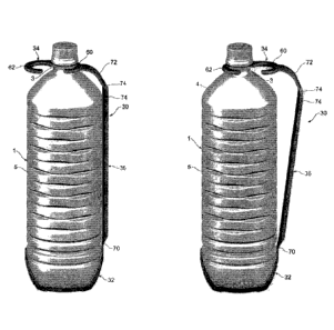
As shown in Figure 1, the gripping part 36 exists as an extension in the
vertical direction in
such a manner that it runs along the body 5 of the bottle 1 in the event that
the neck 3 is engaged in the
first engagement part 60. On the other hand, as shown in Figure 2, the
gripping part 36 exists as an
extension that is inclined relative to the vertical direction in such a manner
that the upper part of the
gripping part 36 draws apart from the bottle in the event that the neck 3 is
engaged in the second
engagement part 62. The lower end part 70 of the gripping part 36 is composed
with rigidity that is
lower than the upper side portion thereof, in such a manner that the
movability of such a gripping part
36 becomes smoother.
Specifically, the gripping part 36 has a pair of flange parts 74, 74 that
extend towards the
outside in opposition to one another, between but not including the lower end
part 70 and the upper end
part 72. The flange parts 74, 74 are separated from one another by just the
width of the gripping part 36.
To cite one example of that width, the thumb of an adult is about the extent
of what is housed between
the flange parts 74, 74. Since the sectional secondary moment of the up-down
intermediate portion of
the gripping part 36 becomes larger due to such flange parts 74, 74, the
rigidity of the up-down
intermediate portion of the gripping part 36 is raised. Since at the same time
the rigidity of the lower end
part 70 of the gripping part becomes lower, the gripping part 36 tends to
become bent, with the lower
end part 70 as the fulcrum, when it changes between the engagement state shown
in Figure 1 and the
engagement state shown in Figure 2. The upper end part 72 of the gripping part
36 has been formed at
an arc-shaped spot that connects the upper side portion of the gripping part
36 and the side of the first
engagement part 60 of the neck supporting part 34, but it is not limited to
this, and it may be formed in
any mode that connects at a right angle the upper side portion of the gripping
part 36 and the side of
the first engagement part 60 of the neck supporting part 34.
In the engaged state shown in Figure 1, as far as the handle 30 composed in
this manner is
concerned, the gripping part exists as an extension in the vertical direction
without any gap or almost
without any gap between it and the body of the bottle 1. At this time, as
shown in Figure 6, it is
configured such that the second engagement part 62 does not protrude greatly
more to the outside
than the second side plate part 46 of the bottom supporting part 32, and
preferably it does not protrude
more to the outside than the second plate side part 46. The maximum width of a
bottle 1 with a handle
30 in the engaged state shown in Figure 1 is the size whereby it fits in the
pocket of a refrigerator, and it
12
CA 02802267 2013-01-21
is set for example at 109 mm. In addition, when the bottle 1 with a handle 30
in the engaged state
shown in Figure 1 is placed horizontally in such a manner that the gripping
part 36 becomes the lower
side, it is configured such that it is supported along the up-down direction
by the flange parts 74, 74.
On the other hand, in the engaged state shown in Figure 2, as the gripping
part 36 faces
upwards, it gradually draws apart from the bottle 1, and a large space is
formed between it and the
upper part of the bottle 1. The width of this space (the distance between the
gripping part 36 and the
bottle 1) is a maximum of about 30 mm between the gripping part 36 and the
shoulder 4, and the user
can insert his hand in this space and grip the gripping part 36. Based on the
design, the width of said
space can be adjusted as needed by the position of the second engagement part
in the neck
supporting part 34. However, based on the standpoint of storability, as noted
above, the position of the
second engagement part 62 is set at the position where it does not protrude
greatly more to the outside
than the second side plate part 46 of the bottom supporting part 32, at the
very least.
A description is now provided of the action effects of the handle 30 in this
mode of embodiment
as described above.
First of all, in order to attach the handle 30 to the bottle 1, in order to
attach the handle 30 to
the bottle 1, the lower part of the bottle 1 is placed on the bottom
supporting part 32, the neck 3 of the
bottle 1 is inserted into the opening part 66 from a horizontal direction, and
the neck 3 is caused to
engage with the first engagement part 60 or the second engagement part 62. It
is configured such that
the handle 30 that is attached in this manner supports the up-down portions of
the bottle 1, and the
user can undertake an operation such as holding the gripping part 36 and
carrying the bottle 1, or
pouring out the contents of the bottle 1.
In the event that the operation of carrying the bottle 1 is performed, if the
neck 3 is engaged in
the second engagement part 62 as shown in Figure 2, a large space in which the
hand can be inserted
is formed between the upper part of the inclined gripping part 36 and the
bottle 1. Owing to this, the
user can easily operate the handle 30. Moreover, it can be operated by placing
the thumb between the
flange parts 74, 74, or placing the thumb on the arc-shaped upper end part 72
of the gripping part 36,
so it is easy to operate.
On the other hand, in the event that it is stored in the pocket, etc. of a
refrigerator, if the neck 3
is engaged in the first engagement part 62 as shown in Figure 1, the gripping
part 36 is positioned in
13
CA 02802267 2013-01-21
such a manner that it approaches the body 5 of the bottle 1 and runs along
this. If the gripping part 36
is folded up in this manner, the gripping part 36 does not occupy a wide
space, and in the event that the
bottle 1 with a handle 30 is placed vertically, one can ensure the storability
to the pocket. To be sure,
even in the event that the bottle 1 with a handle 30 is placed horizontally,
the gripping part 36 does not
occupy such a wide space. Moreover, since it is possible to place it
horizontally with the flange parts 74,
74, even a round bottle 1 can be placed horizontally on a shelf or table, in a
state that prevents it from
falling down.
In addition, since the first engagement part 60 and the second engagement part
62 are
positions in such a manner that they are opposed to one another, the change
between the engaged
state shown in Figure 1 and the engaged state shown in Figure 2 involves just
the operations of pulling
or pushing the gripping part 36 in one direction. Owing to this, it is an
easily movable handle.
Moreover, since the support position of the handle 30 relative to the bottle 1
becomes the up-
down position of the bottle 1, the movement when holding the handle 30,
tilting the bottle 1 and pouring
out the contents is stable. Moreover, the support of the lower portion of the
bottle is performed by
receiving the bottom of the bottle 1. Owing to this, it is not greatly
affected by the design of the bottle
body, and it is possible to support the bottle stably, even in the case of a
lightweight, flexible bottle.
In particular, since the bottom support part 32 supports in such a manner that
it envelopes the
lower portion of the bottle 1, the holdability (controllability) is improved..
In addition, since out of the
peripheral wall of the bottom supporting part, the second side plate part 46
on the side opposed to the
gripping part 36 extends upwards to a certain height from the bottom plate
part 40, even if the bottle is
tilted in order to pour from it, it is possible to support the bottle 1 in
such a manner that it does not come
free from the handle 30.
Moreover, in the event that the bottle 1 is tilted, the lower portion of the
bottle 1 can escape
from the force it receives from the first side plate part 44 or second side
plate part 46 through the
projecting part 50 or projecting part 52 on the groove 8, which achieves the
effect of reinforcement for
the bottle 1. Owing to this, it is possible to inhibit even more optimally the
deformation of the lower
portion of the bottle 1 while improving the holdability of the bottle 1 at the
bottom supporting part 32. In
addition, since the first side plate part 44 and the second side plate part 46
are roughly U-shaped, the
peripheral wall part 42 of the bottom supporting part 32 becomes something in
which an opening is
14
CA 02802267 2013-01-21
formed intermittently in the peripheral direction, so it is possible to aim at
making the weight of the
bottom supporting part 32 lighter.
Next, a description is provided about the handle 100 for the Embodiment 2,
with the focus on
differences between it and the handle 30 for the Embodiment 1, with reference
to Figures 8-10. The
chief differences are a change in the position of the third side plate 480 and
the addition of a leg 110 for
the bottom supporting part 320, and the addition of a curved wall part 120 and
step part 140, 142 for
the gripping part 360. Of the composition of the handle 100, the same numbers
of the key have been
used for those parts with an identical or similar composition as those in the
handle 30 for the
Embodiment 1, and a description thereof has been omitted.
The bottom supporting part 320 is formed in a rough bowl shape overall, in
order to support in
such a manner that it is enveloped from a lower portion of the bottle 1 than
the bottom supporting part
of the Embodiment 1. More specifically, the bottom plate part 40 becomes
roughly round in planar
view, and the area that receives the bottom of the bottle 1 increases. In
addition, the pair of third side
plate parts 480, 480 is positioned upwards from the bottom plate part 40, and
owing to this a lip-shaped
opening is composed between it and the bottom plate part 40. The pair of side
plate parts 480, 480
connects the first side plate part 44 and the second side plate part 46 by a
pair of intermediate parts in
the height direction thereof.
Based on such a configuration, the third side plate parts 480, 480 support a
spot above lower
portion of the bottle compared to the case in the Embodiment 1, when the
bottle is tilted. Therefore, it is
possible to improve further the holdability of the lower portion of the bottle
1. The position or size of the
third side plate parts 480, 480 in the up-down direction towards each other
may be different.
The leg 110 of the bottom support part 320 is formed by protruding from the
outer surface in
the vicinity of the apex of the first side plate part 44, and it has a pair of
installation parts 112, 112
whose gap is wider than that between the pair of flange parts 74, 74. The
installation parts 112, 112
have been composed by a curved surface that protrudes in a mountain shape
towards the side. In
addition, the installation parts 112, 112 are in the same lateral position as
the flange parts 74, 74, in the
engaged state shown in Figure 8. Owing to this, in the event that a bottle 1
with a handle 100 is placed
horizontally in such a manner that the gripping part 36 becomes the lower
side, it is supported by the
installation parts 112, 112 and the flange parts 74, 74. At this time, the
width (gap) of the installation
parts 112, 112 is wider than the width (gap) of the flange parts 74, 74, so it
is possible to place the
CA 02802267 2013-01-21
bottle horizontally even more stably. In addition, in the engaged state shown
in Figure 8, since the leg
110 does not protrude more to the outside than the gripping part 360, the
storability is not impaired, and
it can be provided for uses involving both vertical placement and horizontal
placement. Moreover, when
a bottle 1 with a handle 100 is stored in the pocket, etc. of a refrigerator,
it is possible to use the curved
surface of the installation parts 112, 112 as a guide to the pocket.
The curved wall part 120 of the gripping part 360 is formed by curving upwards
a part of the
upper end part. The curved wall part 120 is curved in such a manner that a
part thereof is positioned
more to the upper side than the neck supporting part 34. Owing to this kind of
curved wall part 120, a
space 130 for a finger rest is formed between the upper end part 72 of the
gripping part 360 and the
shoulder 4 of the bottle 1. To cite an example of this space 130, it is about
the size of a space in which
the thumb of an adult can fit (diameter 1 cm or larger). Owing to this, even
in either of the engaged
states shown in Figure 8 or Figure 9, it is configured such that the user can
insert his finger in the space
130 of the finger rest, and hold the handle 100. Owing to this, it is possible
for example to utilize the
space 130 of the finger rest when the bottle 1 is pulled up from the stored
state in the pocket of the
refrigerator, and moreover it is possible to utilize the space 130 of the
finger rest when the bottle 1 is
moved while it is being carried. Therefore, the portability of the handle that
utilizes the space 130 of the
finger rest and the ease of changing the engaged state are improved.
The step parts 140, 142 of the gripping part 360 are formed on the inner
surface beneath the
upper end part 72. The step part 140 is in a position that corresponds to the
shoulder 4 of the bottle 1,
and the step part 142 is in a position that is lowered by just the width of 4
fingers (about 6-8 cm) from
the step part 140, at a position that corresponds to the upper part of the
body 5. By providing such step
parts 140, 142, when the user grips the upper side portion of the gripping
part 360, the user's fingers
are placed on either one or both of the step parts 140, 142, so it becomes a
device to prevent slipping.
In particular, when the remaining amount of liquid inside the bottle 1
decreases, there is a tendency for
the position at which the user holds the gripping part 360 to become lower,
but since the gripping part
360 has not only the step part 140 on the upper side but also the step part
241 on the lower side
thereof, it is possible to provide a device for preventing slipping that
responds adequately to such a
tendency on the user's part. In addition, owing to the fact that the step
parts 140, 142 have been
provided, it is possible to make the user aware about gripping the upper side
portion of the gripping part
360, and in addition to increase the rigidity thereof.
16
In another mode of embodiment, changed parts other than the step parts 140,
142 may be provided on
the inner surface of the upper side portion of the gripping part 360. For
example, it may be configured in such a
manner that changes are added to the inner surface of the lower side portion,
by doing non-slipping processing
for the inner surface of the upper side portion of the gripping part 360.
As described above, according to the handle 100 for the Embodiment 2, in
addition to the action effects
achieved by the handle 30 for the Embodiment 1, it can achieve action effects
that improve the holding property,
stability during horizontal placement and portability, etc.
Concerning both the first and second modes of embodiment, although the
description herein dealt with a
round bottle as the bottle 1, it goes without saying that one can apply the
handles 30, 100 to bottles shaped like
a polygon, such as a square or rectangle. In this case, the bottom supporting
parts 32, 320 may be configured in
a shape that corresponds to the polygonal shape of the bottle 1. In addition,
in the case of a bottle 1 whose body
has an hourglass shape, it is possible to ensure a larger space owing to the
space between the inclined gripping
part 36, 360 and the body 5, so the gripping part 36, 360 becomes even easier
to hold.
LIST OF THE ELEMENTS
1: Bottle
2: Mouth
3: Neck
4: Shoulder
5: Body
6: Bottom
8: Support ring
9: Groove
11: Bottom wall
12: Peripheral wall
30: Handle
32: Bottom supporting part
34: Neck supporting part
36: Gripping part
40: Bottom plate part
42: Peripheral wall part
17
CA 2802267 2019-03-29
CA 02802267 2013-01-21
,
44: First side plate part
46: Second side plate part
48: Third side plate part
50, 52: Projecting part
60: First engagement part
62: Second engagement part
64: Linking part
66: Opening part
70: Lower end
72: Upper end
74: Flange
100: Handle
110: Leg
112: Installation part
120: Curved wall
130: Space
140, 142: Step part
320: Bottom supporting part
480: Third side plate
18