Note: Descriptions are shown in the official language in which they were submitted.
CA 02802546 2013-01-21
ELECTROSURGICAL APPARATUS WITH INTEGRATED ENERGY SENSING AT
TISSUE SITE
BACKGROUND
Technical Field
The present disclosure relates to an electrosurgical system and method for
performing
electrosurgical procedures. More particularly, the present disclosure relates
to a system and
method for transmitting electrosurgical radio frequency energy from an
electrosurgical generator
to a treatment site and sensor signals from the treatment site to the
electrosurgical generator with
reduced energy loss and tissue site energy control.
Background of Related Art
Electro surgery involves application of high radio frequency electrical
current to a surgical
site to cut, ablate, or coagulate tissue. In monopolar electrosurgery, a
source or active electrode
delivers radio frequency energy from the electrosurgical generator to the
tissue and a return
electrode carries the current back to the generator. In monopolar
electrosurgery, the source
electrode is typically part of the surgical instrument held by the surgeon and
applied to the tissue
to be treated. A patient return electrode is placed remotely from the active
electrode to carry the
current back to the generator.
In bipolar electrosurgery, one of the electrodes of the hand-held instrument
functions as
the active electrode and the other as the return electrode. The return
electrode is placed in close
proximity to the active electrode such that an electrical circuit is formed
between the two
electrodes (e.g., electrosurgical forceps). In this manner, the applied
electrical current is limited
to the body tissue positioned between the electrodes. When the electrodes are
sufficiently
CA 02802546 2013-01-21
separated from one another, the electrical circuit is open and thus
inadvertent contact of body
tissue with either of the separated electrodes prevents current flow.
Bipolar electrosurgery generally involves the use of forceps. A forceps is a
pliers-like
instrument which relies on mechanical action between its jaws to grasp, clamp
and constrict
vessels or tissue. So-called "open forceps" are commonly used in open surgical
procedures
whereas "endoscopic forceps" or "laparoscopic forceps" are, as the name
implies, used for less
invasive endoscopic surgical procedures. Electrosurgical forceps (open or
endoscopic) utilize
mechanical clamping action and electrical energy to effect hemostasis on the
clamped tissue. The
forceps include electrosurgical conductive surfaces which apply the
electrosurgical energy to the
clamped tissue. By controlling the intensity, frequency and duration of the
electrosurgical energy
applied through the conductive plates to the tissue, the surgeon can
coagulate, cauterize and/or
seal tissue.
Tissue or vessel sealing is a process of liquefying the collagen, elastin and
ground
substances in the tissue so that they refoun into a fused mass with
significantly-reduced
demarcation between the opposing tissue structures. Cauterization involves the
use of heat to
destroy tissue and coagulation is a process of desiccating tissue wherein the
tissue cells are
ruptured and dried.
Tissue sealing procedures involve more than simply cauterizing or coagulating
tissue to
create an effective seal; the procedures involve precise control of a variety
of factors. For
example, in order to affect a proper seal in vessels or tissue, it has been
determined that two
predominant mechanical parameters must be accurately controlled: the pressure
applied to the
tissue; and the gap distance between the electrodes (i.e., distance between
opposing jaw members
2
CA 02802546 2013-01-21
or opposing electrodes). In addition, electrosurgical energy must be applied
to the tissue under
controlled conditions to ensure creation of an effective vessel seal.
Transmission of electrosurgical energy to the treatment site, namely from the
electrosurgical generator to the instrument, is accomplished via an
electrosurgical cable. During
transmission an electrical field is generated through the cable and stray
electrosurgical RF energy
is typically emitted along the cable path, which tends to reduce treatment
energy and generates
RF noise. Moreover, the electrical fields may interfere with the operation of
other electronic
equipment in the surgical area, such as patient monitoring equipment.
SUMMARY
The present disclosure relates to transmission of electrosurgical radio
frequency ("RF")
energy and sensor signals. An electrosurgical cable is disclosed having close
proximity electrical
field coupling between a supply and return transmission leads. As used herein,
the term
"electrical field coupling" denotes electrical and electromagnetic fields
generated by the
transmission of RF energy. The coupling maximizes application of the RF energy
delivered
during surgery and minimizes the stray RF energy radiated by the supply and
return leads. Close
proximity electrical field coupling significantly reduces the electrical field
via field cancellation
thereby increasing patient and surgeon safety. Coupling provides a low loss
inductive/capacitive
("LC") transmission medium via a three-dimensional geometric orientation of
the supply and
return leads. The geometric orientation affects LC reactive components and
reduces uncontrolled
capacitively coupled reactance caused by stray RF radiation. In particular,
capacitive reactance is
caused by an antenna effect (e.g., radiative discharge of stray RF energy in
air) for transmission
mediums shorter than half a wavelength. Therefore, the geometric cable
orientation controls the
3
CA 02802546 2013-01-21
loss of stray RF energy, which is contained to a predetermined level and also
reduces capacitive
loading to the energy source (e.g., electrosurgical energy).
In one aspect, an electrosurgical system is disclosed. The electrosurgical
system includes
an electrosurgical instrument having at least one electrode configured as a
first sensor for
measuring a voltage drop. The system also includes a generator having an
output stage coupled
to the at least one electrode and configured to deliver radio frequency energy
thereto; and a
controller configured to measure the delivered radio frequency current at the
tissue site, wherein
the controller is configured to determine actual radio frequency current based
on a measurement
of the radio frequency voltage drop and as a function of resistivity of the at
least one electrode.
In another aspect, an electrosurgical system is disclosed. The system includes
an
electrosurgical instrument having at least one electrode configured as a first
sensor for measuring
a voltage drop at the at least one electrode and as a theimal sensor for
measuring temperature
difference. The system also includes a generator having an output stage
coupled to the at least
one electrode and configured to deliver radio frequency energy thereto; and a
controller
configured to measure delivered radio frequency voltage at the output stage,
wherein the
controller is configured to determine actual radio frequency power based on a
temperature
difference measurement of the at least one electrode and as a function of a
theimal conductivity
of the at least one electrode.
In another aspect, an electrosurgical system is disclosed. The electrosurgical
system
includes an electrosurgical instrument having at least one electrode including
a first sensor
configured in the at least one electrode, the first sensor configured to
measure a voltage drop and
a temperature difference at the at least one electrode. The system also
includes a generator having
an output stage configured to generate radio frequency energy; and a
controller configured to
4
CA 02802546 2013-01-21
measure the delivered radio frequency voltage at the tissue site, wherein the
controller is
configured to deteimine current based on the voltage drop and power based on a
temperature
difference, the controller further configured to calculate the actual
delivered radio frequency
voltage as a function of the calculated power and current.
Another aspect includes a method for controlling an electrosurgical system.
The method
includes delivering radio frequency energy to at least one electrode coupled
to an electrosurgical
generator; measuring a voltage drop at the at least one electrode configured
as a voltage sensor;
measuring current of the radio frequency energy; calculating radio frequency
current as a
function of the voltage drop; and adjusting output of the electrosurgical
generator as a function of
the measured radio frequency current.
In yet another aspect, a method for controlling an electro surgical system is
described. The
method includes measuring and controlling the radio frequency voltage as a
function of derived
current and power through at least one electrode of an electrosurgical
instrument, the
electrosurgical instrument being coupled to a generator; the generator having
an output stage
configured to generate radio frequency energy; and a controller configured to
monitor and adjust
the delivered energy at the tissue site as a function of the measured radio
frequency voltage.
Subsequently in another aspect, a method for controlling an electrosurgical
system is
described. The method includes measuring and controlling temperature at the
tissue site as a
function of at least one of derived current, power or voltage through at least
one electrode of an
electrosurgical instrument, the electrosurgical instrument being coupled to a
generator; the
generator having an output stage configured to generate radio frequency
energy; and a controller
configured to monitor and adjust delivered energy at the tissue site as a
function of the measured
temperature difference.
5
CA 02802546 2013-01-21
Additionally in yet another aspect, a method for controlling an
electrosurgical system is
described. The method includes measuring and controlling tissue impedance as a
function of
derived current and power through at least one electrode of an electrosurgical
instrument, the
electrosurgical instrument being coupled to the generator; the generator
having an output stage
configured to generate radio frequency energy; and a controller
configured to monitor and adjust the delivered energy at the tissue site a
function of the
measured tissue impedance.
BRIEF DESCRIPTION OF THE DRAWINGS
Various embodiments of the present disclosure are described herein with
reference to the
drawings wherein:
Fig. 1 is a schematic block diagram of a prior art electrosurgical system;
Fig. 2 is a schematic block diagram of an embodiment of an electrosurgical
system
according to the present disclosure;
Fig. 3 is a perspective view of an embodiment of an electrosurgical system
according to
the present disclosure;
Fig. 4 is a front view of an electrosurgical generator according to the
present disclosure;
Fig. 5 is a schematic block diagram of the electrosurgical generator of Fig. 4
according to
the present disclosure;
Fig. 6 is a cross-sectional schematic view of an electrosurgical cable
according to the
present disclosure;
Fig. 7 is a schematic view of an electrosurgical system according to the
present
disclosure;
6
CA 02802546 2013-01-21
Fig. 8 is a schematic view of an end effector of the electrosurgical system of
Fig. 7
according to the present disclosure;
Fig. 9 is a cross-sectional, perspective view of an electrosurgical cable of
Fig. 7 according
to the present disclosure; and
Fig. 10 is a flow chart diagram of a method according to the present
disclosure.
DETAILED DESCRIPTION
Particular embodiments of the present disclosure are described hereinbelow
with
reference to the accompanying drawings. In the following description, well-
known functions or
constructions are not described in detail to avoid obscuring the present
disclosure in unnecessary
detail. Those skilled in the art will understand that the invention according
to the present
disclosure may be adapted for use with either monopolar or bipolar
electrosurgical systems and
either an endoscopic instrument or an open instrument. It should also be
appreciated that
different electrical and mechanical connections and other considerations apply
to each particular
type of instrument.
The present disclosure provides for an electrosurgical transmission cable
wound in a
double helix having a proximal geometric relationship in three-dimensional
physical space, to
control the inductive and capacitive components of the transmission cable and
significantly
reduce the capacitive leakage due to RF radiation. The transmission cable
according to present
disclosure is wound in a double helix and minimizes the stray RF radiation by
reducing the
transmitting antenna effect for transmission mediums shorter than 1/2
wavelength.
Fig. 1 is a schematic illustration of a prior art electrosurgical system 101.
The system
includes an electrosurgical generator 103 supplying electrosurgical radio
frequency ("RF") energy
7
CA 02802546 2013-01-21
to a monopolar electrosurgical instrument 104 via a supply transmission lead
118. The RF
energy is returned to the generator 103 through a return electrode 111, shown
as a return pad via
a return transmission lead 119. Conventionally, the supply and return leads
118, 119 are oriented
in a random fashion and thereby emit stray RF energy represented as
uncontrolled radiation 130
due to RF energy flowing therethrough. In particular, random placement of the
supply and return
leads 118, 119 results in uncontrolled capacitive coupling due to stray RF
radiation. RF radiation
produces a transmitting antenna effect caused by random orientation of the
supply and return
leads 118, 119, which also generates an alternate RF leakage path for the RF
energy.
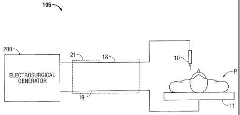
Fig. 2 is a schematic illustration of an electrosurgical system 102 according
to the present
disclosure. The system is a monopolar electrosurgical system that includes an
electrosurgical
instrument 10 having one or more electrodes for treating tissue of a patient
P. With reference to
Figs. 2, 4, and 5, electrosurgical RF energy is supplied to the instrument 10
by a generator 200
via an active lead 18 that is operatively connected to an active output
terminal 230 (Fig. 5) of the
generator 200, allowing the instrument 10 to coagulate, cut, ablate and/or
otherwise treat tissue.
The supply and return leads 18, 19 are enclosed within a cable 21. The
electrosurgical instrument
10 may be coupled to the generator 200 at a connector 250 or 256 (Fig. 4),
each of which is
coupled to the active terminal 230.
Energy is returned to the generator 200 through a return electrode 11 and
transmitted
through a return lead 19, which is operatively connected to a return output
teiminal 232 (Fig. 5)
of the generator 200. The system 102 may include a plurality of return
electrodes 11 that are
disposed on a patient to minimize the chances of tissue damage by maximizing
the overall
contact area with the patient. The return electrode 11 may be coupled to the
generator 200 at a
connector 254 (Fig. 4), which is coupled to the return terminal 232. In
embodiments, the
8
CA 02802546 2013-01-21
generator 200 and the return electrode 11 may be configured for monitoring so-
called "tissue-to-
patient" contact to insure that sufficient contact exists therebetween to
further minimize chances
of tissue damage. The generator 200 may include a plurality of supply and
return terniinals and
corresponding number of transmission cables (e.g., two of each).
Fig. 3 shows a bipolar electrosurgical system 102 according to the present
disclosure.
The system 102 is a bipolar electrosurgical system that includes an
electrosurgical forceps 10
having opposing jaw members 110 and 120. The forceps 10 is shown as an
endoscopic version
of a vessel sealing bipolar forceps. In embodiments, the forceps 10 may be any
suitable
electrosurgical sealing instrument, such as open-type forceps. The forceps 10
also includes a
housing 20, a handle assembly 30, a rotating assembly 80, and a trigger
assembly 70 which
mutually cooperate with the end effector 100 to grasp, seal and, if required,
divide tissue.
Forceps 10 includes a shaft 13 having a distal end 14 that mechanically
engages the end effector
100 and a proximal end 16 that mechanically engages the housing 20 proximate
the rotating
assembly 80. The end effector 100 includes two jaw members 110, 120 movable
from a first
position wherein the jaw members 110, 120 are spaced relative to on another to
a closed position
wherein the jaw members 110, 120 cooperate to grasp tissue therebetween. Each
of the jaw
members 110, 120 includes an electrode 112 and 122, respectively, forniing an
electrically
conductive sealing surface connected to an energy source (e.g., a generator
200). The electrically
electrodes 112 and 122 communicate electrosurgical energy through the tissue
held therebetween.
Electrosurgical RF energy is supplied to the forceps 10 by generator 200 via
the active lead 18
operatively connected to the active electrode (e.g., sealing surface 112) and
returned through the
return lead 19 operatively connected to the return electrode (e.g., electrodes
122).
9
CA 02802546 2013-01-21
Handle assembly 30 includes a fixed handle 50 and a movable handle 40. Handle
40
moves relative to the fixed handle 50 to actuate the end effector 100 and
enable a user to
selectively grasp and manipulate tissue. The jaw members 110 and 120 move in
response to
movement of handle 40 from an open position to a closed position. In the open
position, the
electrodes 112 and 122 are disposed in spaced relation relative to one
another. In a clamping or
closed position, the electrodes 112 and 122 cooperate to grasp tissue and
apply electrosurgical
energy thereto. Jaw members 110 and 120 are actuated using a drive assembly
(not shown)
enclosed within the housing 20. The drive assembly cooperates with the movable
handle 40 to
impart movement of the jaw members 110 and 120 from the open position to the
clamping or
closed position. Examples of a handle assemblies are shown and described in
commonly-owned
U.S. Application Serial No. 10/369,894 entitled "Vessel Sealer And Divider And
Method
Manufacturing Same" and commonly owned U.S. Application Serial No. 10/460,926
entitled
"Vessel Sealer And Divider For Use With Small Trocars And Cannulas."
The forceps 10 also includes a plug 23 that connects the forceps 10 to a
source of
electrosurgical energy, e.g., generator 200, via cable 21. With reference to
Figs. 3-5, the
electrodes 112 and 122 are connected to the generator 200 through cable 21
that includes the
supply and return leads 18, 19 coupled to the active and return terminals 230,
232 (Fig. 5),
respectively. The electrosurgical forceps 10 is coupled to the generator 200
via the plug 23 at a
connector 260 or 262 (Fig. 4), each of which is coupled to the active and
return terminals 230 and
232 (e.g., pins, etc.).
With reference to Figs. 4 and 5, front face 240 of the generator 200 is shown.
The
generator 200 may be any suitable type (e.g., electrosurgical, microwave,
etc.) and may include a
plurality of connectors 250-262 to accommodate various types of
electrosurgical instruments
CA 02802546 2013-01-21
(e.g., electrosurgical forceps 10, etc.). The connectors 250-262 may include
various detection
devices that can read identifying information encoded on the plugs of the
instruments (e.g., plug
23 of the forceps 10). The connectors 250-262 are configured to decode the
infoiniation encoded
on the plugs corresponding to the operating parameters of particular
instruments allowing the
generator 200 to preset energy delivery settings based on the connected
instrument. In
embodiments, data may be encoded in bar codes, electrical components (e.g.,
resistors,
capacitors, etc.), RFID chips, magnets, non-volatile memory, etc., which may
then be coupled to
or integrates into the plug. Corresponding detection devices may include, but
are not limited to,
bar code readers, electrical sensors, RFID readers, Hall Effect sensors,
memory readers, etc. and
any other suitable decoders configured to decode data encoded on the plug.
The generator 200 includes one or more display screens 242, 244, 246 for
providing the
user with variety of output infoiniation (e.g., intensity settings, treatment
complete indicators,
etc.). Each of the screens 242, 244, 246 is associated with a corresponding
connector 250-262.
The generator 200 includes suitable input controls (e.g., buttons, activators,
switches, touch
screen, etc.) for controlling the generator 200. The display screens 242, 244,
246 are also
configured as touch screens that display a corresponding menu for the
electrosurgical instruments
(e.g., electrosurgical forceps 10, etc.). The user then inputs selections by
simply touching
corresponding menu options.
Screen 242 controls monopolar output and the devices connected to the
connectors 250
and 252. Connector 250 is configured to couple to monopolar electrosurgical
instrument (e.g.,
electrosurgical pencil) and connector 252 is configured to couple to a foot
switch (not shown).
The foot switch provides for additional inputs (e.g., replicating inputs of
the generator 200).
Screen 244 controls monopolar and bipolar output and the devices connected to
the connectors
11
CA 02802546 2013-01-21
256 and 258. Connector 256 is configured to couple to other monopolar
instruments. Connector
258 is configured to couple to a bipolar instrument (not shown).
Screen 246 controls bipolar sealing procedures perfouned by the forceps 10
that may be
plugged into the connectors 260 and 262. The generator 200 outputs energy
through the
connectors 260 and 262 suitable for sealing tissue grasped by the forceps 10.
In particular,
screen 246 outputs a user interface that allows the user to input a user-
defined intensity setting.
The user-defined setting may be any setting that allows the user to adjust one
or more energy
delivery parameters, such as power, current, voltage, energy, etc., or sealing
parameters, such as
pressure, sealing duration, etc. The user-defined setting is transmitted to
the controller 224
where the setting may be saved in memory 226. In embodiments, the intensity
setting may be a
number scale, such as from one to ten or one to five. In embodiments, the
intensity setting may
be associated with an output curve of the generator 200. The intensity
settings may be specific
for each forceps 10 being utilized, such that various instruments provide the
user with a specific
intensity scale corresponding to the forceps 10.
Fig. 3 shows a schematic block diagram of the generator 200 configured to
output
electrosurgical energy. In another embodiment, the generator 200 may be
configured to output
other types of energy such as, microwave, laser, etc. to power various other
tissue treatment
devices, such as microwave antennas, ultrasonic forceps, lasers, resistive
heating electrodes, etc.
The generator 200 includes a controller 224, a power supply 227 ("HVPS"),
which may be a high
voltage DC power supply, and an output stage 228. The HVPS 227 is connected to
an AC source
(e.g., electrical wall outlet) and provides high voltage DC power to an output
stage 228, which
then converts high voltage DC power into treatment energy (e.g., laser,
ultrasonic, electrosurgical
or microwave) and delivers the energy to the active terminal 230. The energy
is returned thereto
12
CA 02802546 2013-01-21
via the return terminal 232. The output stage 228 is configured to operate in
a plurality of
modes, during which the generator 200 outputs corresponding waveforms having
specific duty
cycles, peak voltages, crest factors, etc. In another embodiment, the
generator 200 may be based
on other types of suitable power supply topologies.
The controller 224 includes a microprocessor 225 operably connected to a
memory 226,
which non-transitory storage medium readable by a computer (e.g., controller
224) and includes,
but is not limited to non-volatile type memory, flash media, disk media,
etc.). In embodiments,
generator 200 may also include volatile type memory (e.g., RAM). The
microprocessor 225
includes one or more output ports that are connected to the HVPS 227 and/or
output stage 228
allowing the microprocessor 225 to control the output of the generator 200
according to either
open and/or closed control loop schemes. Those skilled in the art will
appreciate that the
microprocessor 225 may be substituted by any logic processor (e.g., control
circuit) adapted to
perform the calculations discussed herein.
The generator 200 may also include a plurality of sensors 229 that provide
feedback to the
controller 224. In particular, the sensors 229 are configured to measure
sourced RF
current and voltage. The term "sourced" as used herein denotes the RF voltage
and current of the
RF waveform generated by the output stage 228 prior as measured prior to the
RF waveform
being transmitted through the cable 321. Such sensors are within the purview
of those skilled in
the art. The controller 224 then signals the HVPS 227 and/or output stage 228,
which then
adjusts the DC and/or power supply, respectively. The controller 224 also
receives input signals
from the input controls of the generator 200 or the forceps 10 and 100, as
discussed above. The
controller 224 utilizes the input signals to adjust the sourced power output
by the generator 200
and/or performs other control functions thereon.
13
CA 02802546 2013-01-21
Fig. 6 shows a cross-sectional view of the cable 21. Cable 21 includes the
supply and
return leads 18, 19 operatively connected to the generator 200 via active and
return terminals
230, 232, respectively. Supply and return leads 18, 19 may be insulated.
Various types of
insulating materials may be used, which are within the purview of those
skilled in the art. The
supply and return leads 18, 19 extend from the active and return terminals
230, 232, respectively,
for a distance A, which is optimally controlled by the location of active and
return terminals 230,
232 and may be from about 0.1 inches to about 6 inches. Leads 18, 19 are then
helix-wound in a
wound portion 35, which may be from about 1 foot to about 20 feet, depending
upon a desired
cable inductance and capacitance. Alternatively, the wound portion 35 may
extend from the
active and return terminals 230, 232 without extending the supply and return
leads 18, 19 for the
distance A.
The wound portion 35, along cable length B, can be of any length depending on
geometric
configuration and physical properties (e.g., tensile strength, flexibility,
etc.) of materials used in
manufacturing of cable components. More specifically, leads 18, 19 are
oriented in a double
helix which includes two congruent helixes with the same axis, differing by a
translation along
the axis. The leads 18, 19 may be oriented in a plurality of other
arrangements which wrap the
leads 18, 19 around themselves. The arrangement of the leads 18, 19 in a
double helix orients the
opposing electrical fields generated by the electrosurgical RF energy passing
therethrough to
mitigate and/or cancel out thereby minimizing the amount of lost stray
electrical RF energy.
The distance D of the portion 35, represents the distance between one apex of
one helix
and a nearest apex of another helix, and may be about 1/2 inch. The distance
E, which is the
distance between two apexes of the same helix may be about 1 inch. The outer
diameter F of the
cable 21 may be about 3/8 of an inch.
14
CA 02802546 2013-01-21
Leads 18, 19 are wound within the cable 21 around a dielectric core 37, which
provides
support for the leads 18, 19. An insulative sheath 39 covers the leads 18, 19.
Dielectric core 37
and the sheath 39 may be of the same type. Leads 18, 19 may include a
conductive trace that has
an inductance rating at about 473 kHz of about 7.37 11 and a capacitance at
about 1 MHz of
about 32.0 PF to yield a cable-self-resonance of about 10.4 MHz. Conductive
trace
configurations are application-dependent and may be optimized for desired
current density and
voltages.
Cable 21 as illustrated in Fig. 6, provides a transmission medium to deliver
RF energy
from the generator 200 to a tissue site. Cable 21 represents one embodiment
for the RF
transmission medium, which reduces the radiated RF electrical field and
maximizes the applied
clinical treatment energy delivered to the tissue site. The dimensions A, B,
C, D, E and F of Fig.
6 form a unique proximal geometric relationship in three dimensional space to
control the
electrical field coupling between the active and return output terminals of
the generator 200 to
significantly reduce the Volts per meter electric field and amps per meter
electromagnetic field
radiation by field cancellation.
The physical dimensions A, B, C, D, E and F are interdependent and may be
optimized to
provide a low loss inductive and capacitive transmission medium, which in
addition to
controlling the electrical field, reduces uncontrolled capacitive coupling
caused by stray RF
radiation. In particular the following formulas (I) and (II) illustrate the
interdependent
relationship of dimensions A, B, C, D, E and F with respect to inductive and
capacitive properties
of the cable 21.
(I)
Inductance = B (10.16 x 10A-9) Ln [(2 x D)/d)] + 2 (A+C) ( H/in for
specified
exemplary conductive wire)
CA 02802546 2013-01-21
(II) Capacitance --- [(B x (0.7065 x 10^-12)) / Ln[(2 x D)/d]]er
In foimulas (I) and (II) "d" denotes diameter of the conductive wire(e.g.,
supply and return leads
18, 19), "er" denotes the dielectric constant of the insulator. Further, E = 2
x D, the ratio of E to
D establishes a continuum of the helix configuration and F = k x E, where "k"
is a constant from
about 0.5 to about 1.5.
At the distal end of the portion 35, the leads 18, 19 are unwound and are
operatively
connected to device connectors 33, 34 respectively, which may be pins disposed
within the
instrument 10. Leads 18, 19 extend a distance C from the portion 35 to the
connectors 33, 34 in
an unwound state for approximately 2.5 feet for monopolar coagulation
applications. In
embodiments, the initial length A of the leads and the unwound state length C
may be equal in
length.
In bipolar electrosurgery, the connectors 33, 34 may be situated on the
forceps 10. In
monopolar surgery, the connector 33 is operatively connected to the instrument
10 and the
connector 34 is connected to the return electrode 11. As discussed above, in
situations where a
plurality of return electrodes are used, the return lead 19 may split into a
corresponding number
of leads to operatively connect all of the return electrodes 11 to the
generator 200. With
monopolar surgery the length C for lead 18 may be of a length greater than 2.5
feet with a
corresponding decrease in lead 19 to accommodate manipulation of surgical
instrument in the
operating site.
Cable 21 according to the present disclosure orients the supply and return
leads 18, 19 so
that the electrical fields generated therethrough are canceled, thereby
reducing the amount of
leaked stray RF energy. More specifically, placement and orientation of the
leads 18, 19 in the
manner discussed above provides for close proximity of electrical fields
generated during
16
CA 02802546 2013-01-21
transmission of electrosurgical RF energy and maximizes amount of energy
delivered to the
treatment site. Reducing the electrical fields also increases safety of
personnel and the patient.
Reduced RF radiation decreases capacitive and RF field leakage and improves RF
control
of the delivered energy. Reduced RF radiation also decreases RF transmission
loss and improves
efficiency of the generator 200 by reducing the RF harmonic component,
minimizing corruption
of the RF source and reducing peripheral conductive and radiative emissions.
Further, reducing
RF radiation also decreases the RF noise to additional equipment found in the
room, such as
patient monitoring equipment.
In addition, the transmission system according to the present disclosure also
provides
novel ways to sense tissue and energy parameters directly at the tissue site.
Conventional
electrosurgical systems sense and control energy delivery at the power source
and calibrate for
the energy transmission losses, but cannot compensate for electrical field
corruptive interference
to the delivered energy. In particular, energy lost during transmission to and
from the instrument
as well as internal loss within the power source may only be approximated due
to an electrical
field interference. Thus, conventional electrosurgical system do not directly
control energy
applied to the tissue or monitor energy and tissue parameters at the tissue
site, which may result
in less than optimal tissue treatment.
The present disclosure provides a system for sensing tissue and energy
parameters directly
at the tissue site allowing for accurate feedback control of the applied
energy to optimally achieve
desired tissue treatment effect including, but not limited to, hemostasis,
vessel sealing, and
coagulation. In particular, the present disclosure includes sensors disposed
at the treatment site
for sensing various tissue and energy parameters and utilizes the transmission
medium (e.g.,
cable 21) to minimize the voltage electric field and current electromagnetic
field components and
17
CA 02802546 2013-01-21
maximize the sensed signal integrity. The sensed signals are then transmitted
to the power source
without compensation for any loss or signal degradation due to conventional
losses described
above. A transmission medium cable for transmitting electrosurgical energy
from a generator to
an instrument is disclosed in a commonly-owned U.S. Patent Nos. 7,819,865 and
7,985,220,
entitled "Electrosurgical Radio Frequency Energy Transmission Medium".
Fig. 7 shows a system 300 including generator 200 and forceps 10. Fig. 8 shows
schematically the end effector 100 including the pair of opposing jaw members
110 and 120 each
having electrodes 112 and 122 disposed within jaw housings 113 and 123,
respectively. The
housings 113 and 123 may be formed by overmolding an insulative material over
the electrodes
112 and 122 to isolate the applied electrical and thermal energy from adjacent
tissue.
System 300 provides control of the treatment energy (e.g., output of the
generator 200) in
a closed loop manner based on the tissue and energy properties sensed directly
at the tissue site.
Parameters of the treatment energy which may be adjusted by the system 300
include, but are not
limited to, energy, power, voltage, current, tissue impedance, rates of change
of these parameters,
and combinations thereof Measured tissue properties include, but are not
limited to, tissue
impedance, tissue temperature, tissue hydrology, tissue vascularity, burst
strength of sealed
vessels, thermal spread, and combinations thereof. Measured energy properties
include, but are
not limited to voltage, current, power, phase, instantaneous, average, and
root mean square values
and combinations thereof.
The system 300 includes electrical sensors for detecting tissue and energy
properties
directly at the tissue site and transmitting the sensor measurements along
electrical and/or optical
cables to the generator 200. With reference to Figs. 7 and 8, the electrical
sensor leads 344a,
18
CA 02802546 2013-01-21
344b, 344c, 345a, 345b, 345c are disposed within a transmission medium (e.g.,
cable 321) of
wound RF supply and return leads 318, 319 to minimize tissue site sensor
signal degradation. In
particular, the cable 321 allows for transmission of sensor signals from
integrated energy-sensing
elements disposed at the end effector 100 with minimal signal degradation. The
system 300
utilizes the sensor signals in a closed loop manner to control application of
treatment energy to
achieve optimal tissue treatment effects.
Forceps 10 is coupled to the generator via the cable 321. Generator 200
includes the
output stage 228 coupled to supply and return leads 318, 319 disposed within
the cable 321. The
supply and return leads 318, 319 are operatively connected to the generator
200 via active and
return terminals 230, 232 respectively. The cable 321 is substantially similar
to cable 21
described above with respect to Fig. 6, thus the embodiment of cable 21 is
incorporated into the
embodiment of cable 321 including, but not limited to, the elements of the
cable 21, such as leads
18, 19, dielectric core 37, insulative sheath 38, and the like, as well
configuration, arrangement,
and material properties of these components.
With respect to Fig. 9, cable 321 includes a dielectic core 337 forming the
core of cable
321. Supply and return leads 318 and 319 are wound about dielectic core 337 in
a double helix
manner and arranged in similar configuration as leads 18 and 19 of Fig. 6.
Dielectric core 337
has a substantially tubular structure having a lumen 338 defined therethrough.
The arrangement
of the leads 318, 319 in a double helix orients the opposing electrical fields
generated by the
electrosurgical RF energy passing therethrough to mitigate and/or cancel out
thereby minimizing
the amount of lost or stray electrical RF energy. Cable 321 also includes an
insulative sheath 339
which is disposed over leads 318 and 319 thereby securing the leads 318 and
319 to the dielectic
core 337.
19
CA 02802546 2013-01-21
Cable 321 as illustrated in Fig. 8, provides a transmission medium to deliver
RF energy
from the generator 200 to the tissue T grasped between the jaw members 110 and
120. Each of
the jaw members 110 and 120 includes electrodes 112 and 122 which are
configured as electrode
sensors and electrodes for delivering RF energy to tissue. The electrodes
include one or more
connections 340a, 340c and 341a, 341c and thermal sensors 340b and 341b,
respectively. The
electrodes 112 and 122 are configured to measure properties of the RF energy
delivered to the
tissue T and may be any suitable electrical sensors including, but not limited
to, conductive
resistors, sense transformers, thennal impedance devices, composite materials
having known
conductive resistivity and thermal conductivity, and combination thereof. The
electrodes 112
and 122 may be disposed in one or both of the jaw members 110 and 120 and are
in electrical
communication with the generator 200, respectively. This configuration allows
the electrodes
112 and 122 to delivery RF energy and to detect electrical current voltage,
phase and other
properties of electrical energy passing directly through the electrodes 112
and 122 without
measuring the current at the generator 200 as performed in conventional
electrosurgical systems.
The measured parameters may then be used to determine various tissue and
energy as described
in further detail below.
The electrodes 112 and 122 are formed from a substantially homogenous material
having
a known electrical resistivity, p, which may be from about 1.4x10⁻³ Ohm per
meter (S2.m) to
about 5.6x10⁻³ C2.m and a known theimal conductivity, k, which may be from
about 2.0 Watt/
meter = Kelvin (W/m=K ) to about 7.0 W/m=K .
The connections 340a, 340c, 341a, 341c are coupled to an electrical sense
processor 342
via one or more electrical sensor leads 344a, 344c, 345a, 345c, respectively.
As shown in Figs. 8
and 9, the leads 344a, 344c, 345a, 345c are disposed within the cable 321 and
pass through the
CA 02802546 2013-01-21
lumen 338. The leads 344a, 344c, 345a, 345c may be insulated. Various types of
insulating
materials may be used, which are within the purview of those skilled in the
art. Sense processor
342 is disposed within the generator 200 and is coupled to the controller 224
and/or the processor
225. Sense processor 342 receives the electrical sense signals from the
electrodes 112 and 122
and deteimines tissue and/or energy parameters at the tissue T and then
transmits the calculations
to the controller 224 through the processor 225. In embodiments, the processor
225 may include
or be coupled to an isolation circuit, e.g., optical isolators, to provide an
isolation barrier between
RF energy and protective earth ground for patient safety. In further
embodiments, the
connections 340a, 340c, 341a, 341c may be directly coupled to the controller
224 such that the
controller 224 performs the functionality of the sense processor 342, namely,
deteimination of
tissue and energy parameters based on electrical sense signals.
As shown in Fig. 8, forceps 10 also includes one or more difference thermal
sensors 340b
and 341b disposed within the jaw members 110 and 120 and coupled to the
electrodes 112 and
122, respectively. As used herein, the term "difference thermal sensor"
denotes a sensor that
measures the temperature difference across each of the electrodes 112 and 122.
Suitable thermal
sensors include, but are not limited to, electronic device thermal sensors,
micro electro-
mechanical thermal sensors, thermocouple devices, infrared devices, fiber
optic thernlal sensors
such as Fiber Bragg gratings, and combinations thereof
Thermal sensors 340b and 341b are coupled to a temperature sense processor 354
via one
or more sensor leads 344b and 345b, respectively. The sensor leads 344b and
345b may be
electrical, optical, or any other suitable connection leads. As shown in Fig.
9, the leads 344a and
345b are disposed within the cable 321 and pass through the lumen 338. Sense
processor 354 is
disposed within the generator 200 and is coupled to the controller 224 and/or
the processor 225.
21
CA 02802546 2013-01-21
Sense processor 354 receives the temperature sense signals from the sensors
340b and 341b and
determines the temperature difference across each of the electrodes 112 and
122 and then
transmits the calculations to the controller 224. In embodiments, the sense
processor 354 may
receive either temperature difference measurements or temperature measurements
directly and
then detennine the temperature difference across each of the electrodes 112
and 122. In further
embodiments, the sense processor 354 may also include or be coupled to an
isolation circuit, e.g.,
optical isolators, to provide an isolation barrier between the RF energy and
protective earth
ground for patient safety. In further embodiments, the sensors 340b and 34 lb
may be directly
coupled to the controller 224 such that the controller 224 perfoinis the
functionality of the sense
processor 354, namely, determination of sealing surface temperature based on
electrical or optical
sense signals.
In response to the electrical and temperature sense signals, the controller
224 may adjust
the output of the generator 200. In embodiments, the controller 224 may
include one or more
algorithms for controlling the output as a function of the detected tissue
and/or energy properties.
In particular, the algorithm implemented in the controller 224 may drive the
output of the
generator 200 as well as its components, including the temperature sense
processor 354 and the
electrical sense processor 342 to continuously monitor tissue and/or energy
properties for
adjustment of the generator output.
Fig. 10 shows a method for monitoring tissue and controlling energy properties
using the
system 300 of Fig. 7. In step 400, the generator sources the radio frequency
energy to the
instrument 10 over the helix transmission cable 321 where the energy is
delivered to the tissue
site via electrodes 112 and 122. Sensor 229 monitors the sourced energy
generated and provides
input to controller 224, as it is transmitted over the helix cable.
22
CA 02802546 2013-01-21
In step 402, generator 200 measures the voltage drop AVdrop across each of the
electrodes
112 and 122 via connections 340a, 340c, 341a, 341c, which is transmitted to
controller 224 over
an isolation barrier incorporated in the electrical sense processor of 342.
Controller 224 receives
the isolated voltage drop from 342 and calculates the RF current delivered to
the tissue as a
function of the electrical resistivity of the electrodes 112 and/or 122.
This determination may be performed by the controller in step 404 via the
formula (III)
below:
(III) RF current (Irf) AVdrop / R
In formula (III), R is electrode resistance, which may be calculated via the
foimula (IV)
(IV) R = KO) / A]
In formula (IV) A is electrode area in meters squared, / is the electrode
length in meters, p is
resistivity. The values A, /, and p may be stored in the memory 226 such that
the resistance R
may be calculated for each instrument 10. It is envisioned that various
instruments 10 may
include electrodes 112 and 122 of various sizes, resistance, and other
properties. These
properties may be communicated to the generator 200 via identification systems
discussed above
or otherwise input by the user.
Controller 224 determines actual RF current and controls the delivered energy
to the
tissue site in step 406 as a function of the calculated actual RF current.
Differences in the sourced
energy sensed by the sensor 229 and the delivered energy as calculated by the
controller 224
based on the voltage drop are adjusted in step 408, where an error signal is
returned by the
controller 224 to adjust RF output of the generator 200 by controlling the
output stage 228 and/or
the power supply 227. In step 400, the controller 224 corrects the delivered
RF current for closed
loop controlled delivery of the tissue treatment energy and effective
hemostasis of tissue.
23
CA 02802546 2013-01-21
In step 410, which may be perfolined concurrently with the step 402, the
generator 200
measures AT, the temperature difference across each of the electrodes 112 and
122 via thermal
sensors 340b, 341b. The temperature difference signal is transmitted via leads
344b and 345b to
controller 224 over an isolation barrier, incorporated in the temperature
sense processor 354.
Controller 224 receives the processed temperature difference from the
processor 354 and
calculates the RF power delivered to the tissue as a function of the thermal
conductivity of the
electrodes 112 and 122. This calculation is performed in step 412 using the
formula (V) below:
(V) RF power (P) = T / 0
In foimula (V), e is thermal impedance ( C/Watt) which may also be expressed
as thennal
conductivity, k, [Watt / (m=K)], where K is temperature in degrees Kelvin, and
m is meters.
These values may be stored in the memory 226 as described above with respect
to the resistivity,
dimensions and other properties of the electrodes 112 and 122.
Controller 224 determines actual RF power and controls the delivered energy to
the tissue
site in step 416, as a function of the calculated actual RF power. Differences
in the sourced
energy as measured by the sensor 229 and the delivered energy are adjusted in
step 408, where an
error signal is returned by the controller 224 to adjust RF output of the
generator 200 by
controlling the output stage 228 and/or the power supply 227. In step 400, the
controller 224
corrects the delivered RF power for closed loop controlled delivery of the
tissue treatment energy
and effective hemostasis of tissue.
As represented in formulas (III)-(V), p is the electrical resistivity and k is
the thermal
conductivity of the electrodes 112 and 122, Irf is the actual RF current
delivered to the
tissue as calculated in equation (III) and P is the actual RF power delivered
to the tissue as
calculated in equation (V). The electrical resistivity and thermal
conductivity of the sealing
24
CA 02802546 2013-01-21
electrodes 112 and 122 is stored in the memory of 226 as described above. In
embodiments, the
electrical resistivity and theinial conductivity may be pre-calculated based
on the geometry of the
electrodes 112 and 122 and its material properties or composition for a range
of temperatures,
which may be stored in a look-up table in the memory 226. In further
embodiments, the electrical
resistivity and thermal conductivity may be adjusted in real time as a
function of the material
characteristic temperature, also stored in memory 226, to compensate for
electrode resistance R
and thermal impedance changes due to temperature variations encountered during
energy
applications. The controller 224 utilizes the stored temperature variant
electrode resistance R and
thermal impedance 0, to calculate the actual RF current and power as
represented in equations
(III) and (IV).
In step 418, controller 224 calculates the RF voltage (V) and tissue impedance
(Z) as a
function of the RF current and RF power, which were previously calculated in
steps 404 and 412,
respectively. The calculation performed in step 418 may be performed using the
formulas (VI)
and (VII) below:
(VI) RF Voltage (V) = P / Id
(VII) Tissue Impedance (Z) = P / I2rf
In step 420, controller 224 processes either one or both of the calculated RF
voltage (V)
and the tissue impedance (Z) and controls the delivered energy to the tissue
site in step 420, as a
function of the generated radio frequency RF voltage or tissue impedance which
were calculated
in step 418. Differences in the sourced energy as measured by the sensor 229
and the delivered
energy are adjusted in step 408, where an error signal is returned by the
controller 224 to adjust
the electrosurgical generator output 228 via power supply 227, represented in
step 400,
to correct the delivered RF voltage or tissue impedance for closed loop
controlled delivery of the
CA 02802546 2013-01-21
tissue treatment energy and effective hemostasis of tissue.
In step 422, controller 224 processes one or more of the RF power, voltage,
current, tissue
impedance, or combinations thereof to control the delivered energy to the
tissue site, a function
ofthe tissue temperature (T). Differences in the sourced energy as measured by
the sensor 229
and the delivered energy are adjusted in step 408, where an error signal is
returned by the
controller 224 to adjust RF output of the generator 200 by controlling the
output stage 228 and/or
the power supply 227. In step 400, the controller 224 corrects the delivered
RF energy for closed
loop controlled delivery of the tissue treatment energy and effective
hemostasis of tissue.
While several embodiments of the disclosure have been shown in the drawings
and/or
discussed herein, it is not intended that the disclosure be limited thereto,
as it is intended that the
disclosure be as broad in scope as the art will allow and that the
specification be read likewise.
Therefore, the above description should not be construed as limiting, but
merely as
exemplifications of particular embodiments. Those skilled in the art will
envision other
modifications within the scope and spirit of the claims appended hereto.
26