Note: Descriptions are shown in the official language in which they were submitted.
- 1 -
METHOD FOR STERILIZING AT LEAST ONE OBJECT,
STERILIZATION APPARATUS AND USE HEREFOR
The present invention relates to a method and to an apparatus for sterilizing
one or
more objects.
The sterilization processes used today such as the so-called ETO
sterilization,
gamma radiation or also steam sterilization are unsuitable for certain
sterilization
procedures since they in part work with high temperatures and so may damage
the
object to be sterilized, cause excessive costs and/or are not environmentally
friendly.
This applies above all to the named ETO sterilization.
It is furthermore known to carry out the sterilization with the aid of ozone.
This has
the advantage, in particular over ETO sterilization, that e.g. the ozone and
H202 can
be converted to oxygen and water and thus made harmless via a catalytic
converter
after sterilization has taken place. Sterilization methods which work under
the use of
ozone are likewise known from the prior art.
It is thus known from EP 1 175 230 B1 and EP 1 455 843 B1, for example, to
carry
out a sterilization procedure such that the humidification of the atmosphere
located in
the sterilization chamber takes place after the evacuation of a sterilization
chamber
and then the filling with ozone whereby a sterilization procedure is
initiated. These
treatment steps are repeated before the sterilization chamber is flushed and
finally
opened so that the sterilized objects can be removed. The apparatus and
methods
known from the named documents are only suitable in practice for small units
such
surgical instruments in small containers due to their design and to the
conducting of
the method.
It is therefore the object of the present invention to further develop a
method and an
apparatus of the initially named kind in an advantageous manner, in particular
such
that a sterilization method and an apparatus herefor are provided by means of
which
a safe and reliable sterilization is also possible of objects which are
difficult to
sterilize, such as long hose systems and/or hose systems closed at one side.
CA 2802765 2018-04-27
- 2 -
This object is achieved in accordance with the invention by a method as
described
herein. Provision is accordingly made that in a method for sterilizing at
least one
object, the object is exposed to a sterilization agent, wherein at least one
first
support pressure and at least one second support pressure are applied and
wherein
a sterilization of at least one first region of the object takes place by the
sterilization
agent at the first support pressure and a sterilization of at least one second
region of
the object takes place at the second support pressure.
The advantage in particular thereby results that an ETO-free, reliable and
safe
sterilization can be achieved. The support pressure can be generated by the
addition
of a support gas in a sterilization chamber, whereby the sterilization agent
introduced
into the sterilization chamber acts on the object to be sterilized and
sterilizes it
regionally.
It is in particular possible that the object is a disposable of some kind
which has
regions such as e.g. a lumen or the like which are difficult to access by the
sterilization agent due to the geometry of the object.
The object can be a hose system, in particular a medical hose system or a so-
called
hose kit, for instance for use in hemodialysis. This hose system is preferably
sterilized regionally in dependence on this support pressure. Depending on the
applied support pressure, the sterilization agent can be transported into the
lumen of
the hose system.
It is in particular possible to be able to sterilize long hose systems or hose
kits even if
they are introduced into gas-permeable outer packaging and/or are closed at
one
side.
It can advantageously thus be prevented that at high pressure values the
sterilization
agent is concentrated at the center of e.g. hose systems to be sterilized,
whereas it
is diluted at the respective ends by the support gas. It becomes possible to
take the
circumstance into account that when a low support pressure is used, the
CA 2802765 2018-04-27
CA 02802765 2012-12-14
- 3 -
outer ends of the object to be sterilized are rather reached, the hose ends in
a hose
system, for instance. It now becomes possible by the use of different support
pressures to fill all the regions of the object to be sterilized in a targeted
manner by
the sterilization agent. It is particularly advantageous that the
sterilization is also
possible in all regions of a closed lumen.
A further advantage is that a safe alternative to so-called gamma
sterilization is
provided. It can in particular thus be prevented that a change to the
material, in the
worst case damage to the material, of the object to be sterilized arises as a
consequence of the radiation
It is furthermore conceivable that the sterilization agent at least partly
includes
ozone and/or hydrogen peroxide or one or more of the reaction products of
these
substances. For example, when hydrogen peroxide is used as the sterilization
agent, a preheating of the sterilization chamber and of the sterilization
product is
carried out. On the use of ozone as the sterilization agent, this is not
absolutely
necessary. It is generally conceivable, for example, only to use hydrogen
peroxide
or only ozone as the sterilization agent.
It is furthermore possible that the at least one first support pressure and/or
the at
least one second support pressure is/are generated by introduction of a
support gas
into a sterilization chamber.
Provision can be made in dependence on the application purpose and on the
property of the object to be stabilized that the at least one first support
pressure
and/or the at least one second support pressure is/are particularly
advantageously
below atmospheric pressure. Provision can alternatively be made that the at
least
one first support pressure and/or the at least one second support pressure
is/are at
or above atmospheric pressure.
It is of advantage if the support gas at least partly includes or is an inert
gas and/or
air, preferably sterile air.
CA 02802765 2012-12-14
- 4 -
It is conceivable that in a first step, the object to be sterilized is
inserted into a
sterilization chamber; in a second step, the sterilization chamber is
evacuated; and,
in a third step, the sterilization chamber is humidified and sterilization
agent is
introduced into the sterilization chamber; in a fourth step, the first support
pressure
.. is applied; in a fifth step, the first support pressure is maintained for a
point in time
or for a duration; in a sixth step, steps two to five are repeated once or a
multiple of
times; and in a seventh step, the at least one second support pressure is
applied.
On the increase in pressure, precipitation of the liquid dissolved in the
atmosphere
takes place. A mist-like atmosphere is hereby created which shows additional
effect
as an aerosol. It can be generated by fast cooling of a saturated gas or,
here, also
by a fast increase in the pressure, with the latter variant being a preferred
embodiment of the invention.
It is furthermore possible that in the seventh step, steps two to five or two
to six are
carried out using the second support pressure.
Provision can advantageously further be provided that in at least one further
step,
one or more further support pressures are applied and that steps two to five
or two
to six are carried out accordingly using the further support pressures.
It is furthermore conceivable that the humidification of the sterilization
chamber
takes place in that a liquid, in particular a mixture containing water and
hydrogen
peroxide, is brought to vaporization by application of a vacuum, in particular
by
evacuation, and the vaporized liquid is supplied to the sterilization chamber.
It is of
advantage that this steam created in this manner and containing hydrogen
peroxide
in any case does not reach a high temperature which could damage the
sterilization
product. It is namely a comparatively cold steam.
Provision can moreover be made that the first support pressure is at least
approximately 500 mbar abs and/or that the second support pressure is at least
approximately 50 mbar abs.
CA 02802765 2012-12-14
- 5 -
It is furthermore possible that a third support pressure is applied, wherein
the third
support pressure is preferably up to 50 mbar abs and/or corresponds to the
gassing
pressure without additional introduction of a support gas, wherein the fourth
step,
that is, the application of the support pressure, is already carried out by
step 3, that
.. is, the introduction of the sterilization agent into the sterilization
chamber.
In particular, every pressure or support pressure preferably has an upper
limit which
amounts to around 1100 mbar.
.. It is further possible that the sterilization agent is introduced into the
sterilization
chamber in the form of an aerosol.
Provision can be made that the aerosol is formed by steam containing hydrogen
peroxide. Provision can be made, for example, that the hydrogen peroxide used
as
sterilization agent is directed into the sterilization chamber as steam.
It is also conceivable that the aerosol arises by the introduction of ozone
into the
liquid which contains water and/or hydrogen peroxide. It is, for example,
conceivable to conduct ozone gas through a so-called Laskin nozzle. The outlet
opening of this nozzle is arranged beneath the level of a liquid which
comprises
hydrogen peroxide and/or water or which includes one or more of these
substances. There are no liquid drops, which have a very large surface overall
and
which are in direct contact with the ozone gas, in the arising gas bubble
comprising
ozone. The contact of the ozone with water and/or with hydrogen peroxide
results in
the activation of the liquids by a reaction between water and/or hydrogen
peroxide
and the ozone. This reaction results in the splitting of the water or the
hydrogen
peroxide and to radical formation. The hydroxide radicals OH- are reactive and
aggressive and effect the desired sterilization success by killing
microorganisms.
Due to the comparatively large contact surface between the liquid with the
ozone
gas, a number of the named reactions are stimulated so that a correspondingly
high
yield of OH- radicals is present.
CA 02802765 2012-12-14
- 6 -
Provision is made in a further embodiment of the invention that the
introduction of a
sterilization agent into the sterilization chamber takes place at a pressure
in the
sterilization chamber which is below the atmospheric pressure.
This procedure makes it possible always to keep the aerosol container and/or
aerosol generator at a pressure value which is below the atmospheric pressure
during the entire operation. This procedure brings along the advantage that a
topping up of the aerosol container with hydrogen peroxide or water is
particularly
simple since only one metering valve has to be opened through which the
corresponding liquid can then subsequently be drawn.
It is moreover conceivable that the holding of the support pressure preferably
takes
place for a duration, in accordance with the fifth step, that is, the holding
of the
support pressure for a point in time or a duration, whose length is in the
range < 20
minutes, preferably < 10 minutes, and particularly preferably < 5 minutes.
Provision can furthermore advantageously be made that the duration between two
application steps taking place successively, preferably in accordance with the
fourth
step, that is, the application of the support pressure, is in the range <20
minutes,
preferably < 15 minutes, and particularly preferably < 10 minutes.
It is furthermore conceivable that after the last method step, in particular
the
seventh step, that is, the application of the at least one second support
pressure, or
after termination of the sterilization, the flushing and degassing of the
sterilization
chamber is carried out, wherein the flushing and degassing is preferably
carried out
several times.
It is conceivable to design this flushing and degassing phase by repetitions
of
evacuations and ventilations. It is likewise advantageously conceivable to
provide a
drying phase which is preferably carried out in the evacuated state of the
sterilization chamber. The sterilization procedure can then be terminated.
- 7 -
An advantageous embodiment of the method can comprise the sequence of steps
two to five lasting approximately 15 to 20 minutes, preferably approximately
18
minutes.
The invention furthermore relates to a sterilization apparatus having the
features as
described herein. Provision is accordingly made that the sterilization
apparatus has
at least one sterilization chamber for the reception of at least one object to
be
sterilized, at least one first means for the supply and/or removal of a
sterilization
agent, and at least one second means by means of which at least one first
support
pressure and at least one second support pressure can be applied, and wherein
at
the first support pressure of the sterilization agent a sterilization of a
first region of
the object can be carried out and a sterilization of a second region of the
object can
be carried out at the second support pressure.
The first means can advantageously be a supply line in which at least one cut-
off
valve is present. It is conceivable that the supply line is simultaneously a
removal
line. It is, however, generally advantageously possible to make the supply
line and
the removal line separately from one another. The second means can have a
support gas supply with a corresponding pressure regulation, wherein the
supply
line for the support gas advantageously has at least one valve. Different
support
pressures can be set via the pressure regulation.
Provision can be made that the sterilization apparatus has at least one
control
and/or regulation means by means of which the sterilization procedure can be
controlled and/or regulated and/or monitored, can preferably be
semiautomatically
and/or fully automatically controlled and/or regulated and/or monitored. This
control
and/or regulation means can, for example, be a part of the central control
and/or
regulation unit of the sterilization apparatus.
It is further possible that the first support pressure and/or the second
support
pressure can be applied by means of the second means at a pressure which is
particularly advantageously below atmospheric pressure. It is alternatively
also
CA 2802765 2019-08-19
- 8 -
conceivable that the first support pressure and/or the second support pressure
can be
applied by means of the second means at a pressure which is at or above
atmospheric
pressure.
It is particularly advantageous if a method as described herein can be carried
out with
the sterilization apparatus. It is conceivable that the carrying out of the
method can be
controlled and/or regulated and/or monitored, can preferably be
semiautomatically
and/or fully automatically controlled and/or regulated and/or monitored, by
the control
and/or regulation means.
The present invention furthermore relates to a use of a method for sterilizing
and/or of a
sterilization apparatus having the features as described herein. Provision is
accordingly
made that a method as described herein and/or a sterilization apparatus as
described
herein is used for sterilizing at least one object, in particular a medical
hose kit.
The present invention further relates to a sterilized object having the
features as
described herein. Provision is accordingly made that a sterilized object, in
particular a
medical hose kit, is obtained using a sterilization apparatus as described
herein and/or
by means of a method as described herein.
The object preferably has at least one means by means of which the
sterilization
procedure which has taken place is or can be displayed. This can, for example,
be a
print which indicates the type of the sterilization method and is e.g. applied
to the
packaging of the hose kit. It is particularly advantageous if the means or the
print is
made such that its quality is changed by the sterilization procedure and
hereby allows
the recognition that the sterilization procedure was successful. This can take
place, for
example, by a color change of the means as a consequence of the contact with
the
sterilization agent. It is conceivable that the means indicates or that it can
be indicated
by the means whether the method as described herein was carried out
successfully or
not.
CA 2802765 2018-05-01
- 8a -
According to one aspect of the present invention, there is provided a method
for
sterilizing at least one medical hose kit, wherein the medical hose kit is
exposed to a
sterilization agent, wherein at least one first support pressure and at least
one second
support pressure are applied and wherein a sterilization of at least one first
region of the
medical hose kit takes place by the sterilization agent at the first support
pressure and
a sterilization of at least one second region of the medical hose kit takes
place at the
second support pressure, wherein the at least one first support pressure and
the at least
one second support pressure are generated by introducing a support gas into a
sterilization chamber, wherein the support gas is introduced into the
sterilization
chamber after introduction of the sterilization agent, and wherein the support
gas is an
inert gas or air, and wherein the first support pressure and the second
support pressure
are different.
CA 2802765 2018-11-30
CA 02802765 2012-12-14
- 9 -
Further details and advantages will now be explained in more detail with
reference
to an embodiment shown in the drawing. There are shown:
Figure 1: a schematic representation of a sterilization apparatus in
accordance
with the present invention;
Figure 2: a representation of the pressure profile in the sterilization
chamber
during a sterilization cycle; and
Figure 3: a schematic representation of a medical hose kit with indication
of the
different sterilization regions.
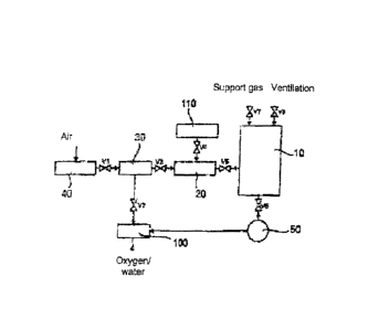
Figure 1 shows a block diagram for an embodiment of a sterilization apparatus
in
accordance with the present invention. A sterilization chamber is labeled by
the
reference numeral 10 which can, for example, have a volume of at least 1 m3
and a
door which serves both loading and unloading. The objects to be sterilized can
be
introduced into the sterilization chamber 10, for example, on steel baskets on
one or
more levels. 150 to 200 products can be sterilized simultaneously depending on
the
product size. An aerospace container 20 or a vaporizer 20 is connected before
the
.. sterilization chamber 10.
As can furthermore be seen from Figure 1, an oxygen generator 40 is connected
before the ozone generator 30 and 95% oxygen can be acquired from the
environmental air in it. A molecular screen or zeolite serves this purpose,
for
example. The oxygen is converted into ozone in the ozone generator 30, which
can
take place, for example, by a dielectric barrier discharge.
If the method in accordance with the invention is only carried out with
hydrogen
peroxide, the Figure shown in Fig. 1 can be made correspondingly modified. For
example, the ozone generator 30 can then be dispensed with. Instead, for
example,
a reservoir or tank can be provided for the hydrogen peroxide or generally a
hydrogen peroxide supply can be provided. The hydrogen peroxide is preferably
- 10 -
introduced into the sterilization chamber 10 in steam form, for instance as
liquid
vaporized by evacuation.
A catalytic converter is labeled by the reference numeral 100 in Figure 1
which is
suitable to decompose the sterilization agent after its use, in particular to
decompose
hydrogen peroxide and/or ozone or their reaction products. Only water and
oxygen are
then created as decomposition products. The catalytic converter 100 can, for
example,
be manganese dioxide.
To generate the desired vacuum in the sterilization chamber 10, a vacuum pump
50 is
connected after said sterilization chamber which results in an evacuation of
the
sterilization chamber 10 with an opened valve V6 and with a vacuum pump 50 in
operation. Sterile air is introduced as the support gas into the sterilization
chamber 10
via the valve V7. Finally, a unit is indicated by the reference numeral 110
which serves
the metering in of water and/or hydrogen peroxide into the aerosol container
20 or to the
vaporizer 20.
The sterilization procedure has the following form in detail:
After the insertion of the object or objects into the sterilization chamber
10, a vacuum is
generated in the sterilization chamber 10, for which purpose only the valve V6
in
accordance with Figure 1 is opened and all the further valves V1, V2, V3, V4,
possibly
V5, V7 and V8, are closed. The generation of the vacuum results in a reduction
of the
chamber pressure.
The pressure in the chamber 10 preferably drops to a value < 10 mbar in step
200 due
to the evacuation of the sterilization chamber 10 by means of the vacuum pump
200.
For the humidification, the valve V5 in the line between the aerosol container
20 or the
vaporizer 20 and the sterilization chamber 10 can e.g. be opened so that a
vaporization
of the liquid in the aerosol container 20 takes place, provided its vapor
CA 2802765 2018-04-27
CA 02802765 2012-12-14
- 11 -
pressure is fallen below, lithe vapor pressure of the liquid, i.e. for example
of the
mixture of water and hydrogen peroxide, is fallen below in the aerosol
container, it
starts to vaporize and in this manner enters into the sterilization chamber
10. The
vacuum pump 50 is thus not used only for evacuating, but also for vaporizing
the
.. liquid in the aerosol container 20.
A sterilization agent is actively introduced into the sterilization chamber 10
simultaneously with the step of humidifying. This method step is labeled by
the
reference numeral 201 in Figure 2. Hydrogen peroxide is advantageously
introduced as the sterilization agent into the sterilization chamber as vapor
here, for
example.
Alternatively, the creation of hydroxide radicals can take place due to the
contact of
the ozone with water and/or hydrogen peroxide, said hydroxide radicals
entering
into the sterilization chamber 10 with the aerosol and there contributing to
the
sterilization process or representing the decisive sterilization agent.
The valves V3 and V5 or V4 and V5 are opened and all the further valves are
closed during the method step 201 in accordance with Figure 3. The aerosol
containing ozone enters into the sterilization chamber 10 due to the pressure
drop
between the ozone generator 30 and the sterilization chamber 10.
This applies correspondingly to the hydrogen peroxide vapor when hydrogen
peroxide is used as the sterilization agent instead of ozone.
A pressure increase thereby occurs such as can be seen from Figure 2. This
pressure increase is a measure for the quantity of the sterilization agent in
the
sterilization chamber 10. In this respect, the concentration is set to a value
ideal for
the product to be sterilized.
After the introduction of the sterilization agent, the pressure in the
sterilization
chamber 10 is increased by means of a support gas via the valve V7, as is
shown in
CA 02802765 2012-12-14
- 12 -
step 202 in accordance with Figure 2. In the embodiment shown there, the
pressure
is increased to a first support pressure of approximately 500 mbar abs. This
support
gas enters into the sterilization chamber 10 in that the valve 7 in accordance
with
Figure 1 is opened for a predetermined duration or until a specific pressure
value is
reached. All the further valves of the apparatus are closed during this method
step.
V5 can alternatively also be open.
The sterilization phase in which the first pressure gas is applied is called
the first
sterilization phase S1.
As can further be seen from Figure 2, the first support pressure is held in
the
sterilization chamber 10 for a specific duration. This method step is
identified by the
reference numeral 203 in Figure 2 and can be, for example, a minute or in the
minute region.
After the holding of the support pressure for a specific duration in
accordance with
step 203 in Figure 2, this process step comprising the steps 200 to 203 are
carried
out four times in total, i.e. it is evacuated, then humidified and the
sterilization agent
is introduced and then the first support pressure is again generated and held
for a
specific duration.
After the fourfold carrying out of the steps 200 to 203, the first
sterilization phase Si
is terminated and the process continues with the second sterilization phase
S2. In
the sterilization phase S2, the second support pressure is applied which here
amounts to 50 mbar abs and the steps 200', 201', 202' and 203' are carried out
a
total of six times. In this respect, steps 200' to 203' correspond to steps
200 to 203
from the sterilization phase Si, i.e. it is evacuated, then humidified and the
sterilization agent is introduced and then the second support pressure is
generated
again, with the difference that the second support pressure in the
sterilization phase
.. S2 amounts to 50 mbar abs.
CA 02802765 2012-12-14
- 13 -
Due to the fact that the filling of the sterilization chamber 10 with
sterilizing agent in
accordance with step 201, 201', 201" is terminated when a substantial
underpressure is present in the sterilization chamber 10, it can generally be
achieved that an underpressure is always present in the aerosol generator 20.
This
makes it possible that liquid, i.e. water, hydrogen peroxide and/or a mixture
of both
substances, can subsequently easily be drawn from a reservoir 110 by opening
the
valve V4.
As can furthermore be seen from Figure 1, the pump 50 is in communication at
the
outlet side with the catalyst 100 so that the medium arising at the pressure
side of
the pump can be decomposed in the catalyst 100.
It is generally conceivable to repeat and/or to vary the sterilization phases
Si and
S2, for example, or to carry out further sterilization phases at different
support
pressures subsequently to the sterilization phases shown in Figure 2.
This is followed in the embodiment shown here by the flushing and degassing of
the
sterilization chamber 10 by multiple evacuation and ventilation. This phase is
not
shown in any more detail in Figure 2.
An evacuation and a ventilation of the sterilization chamber 10 takes place
multiple
times during the flushing and degassing phase. This phase can be followed by a
drying phase in which there is preferably a vacuum in the sterilization
chamber 10.
Figure 3 shows a hose system 300 or a so-called hose kit 300 which was
sterilized
by means of the apparatus and method shown in Figures 1 and 2. It is a hose
kit
300 for dialysis which can have a total hose length of up to 6 m in dependence
o
the treatment process.
The packing for the hose kit 300 in which the hose kit 300 is, however,
preferably
sterilized is not shown. It is conceivable that at least one support pressure
above
the atmospheric pressure is applied or is being applied in such a case.
CA 02802765 2012-12-14
- 14 -
The hose kit 300 in accordance with Figure 3 is a hose kit 300 for the
extracorporeal blood circuit which in particular has a needle 302 for
connection of
the hose kit 300, e.g. to the shunt of the patient, a connector 304 e.g. for
connection
to the dialyzer, not shown, inflows and outflows 310, 312, 314, 316 closed by
closure caps and pressure measurement connections 320, 322.
The regions labeled with B1 are sterilized by the application of the first
support
pressure of approximately 500 mbar abs, that is, during the sterilization
phase S1
shown in more detail in Figure 2. All the regions of the hose kit 300 in which
the
.. lumen of the hose kit 300 is closed at the end side are affected, that is,
the inflows
or outflows 310, 312, 314, 316 closed by closure caps and the pressure
measurement connections 320, 322. It is conceivable that with particularly
long
hose kits 300, the middle region of the hose kit 300 is likewise sterilized
during the
sterilization phase Si.
The regions labeled by B2 are likewise sterilized by the application of the
first
support pressure of approximately 500 mbar abs. All the regions of the hose
kit 300
which are in the inner region of the lumen of the hose kit 300 are affected so
that
the first support pressure 300 is necessary or sufficient to transport the
sterilization
agent in it.
The regions labeled with B3 are sterilized by the application of the second
support
pressure or gassing pressure of approximately 50 mbar abs, that is, during the
sterilization phase S2 shown in more detail in Figure 2. These regions in
Figure 3
are here the start regions and end regions of the hose kit 300, that is, the
regions
which follow the needle 302 and the connection 304 respectively.