Note: Descriptions are shown in the official language in which they were submitted.
CA 02802774 2012-12-14
WO 2012/000019 PCT/AU2011/000785
1
MODULAR WATER TREATMENT SYSTEM
Technical Field
This invention relates to the treatment of substances such as liquids, and in
particular relates to the treatment of contaminated water which may form a
body of
water such as a lake or dam, be flowing in a watercourse such as a river bed,
or
be the output from an industrial process. More particularly, the invention
relates to
a modular water treatment system for operation in such locations, or for
dealing
with the results of such processes.
Background Art
A general overview of the treatment of contaminated water is contained in WO
2004/067455. Prior treatment systems and apparatus, more specifically directed
towards the area of the present invention, feature a vessel which is adapted
to
float in a body of water to be remediated. WO 2007/121509 discloses a buoyant
body which floats on a body of water, the body supporting a tank in which
water
pumped from the body of water is exposed to bacteria to treat the water. WO
2009/029381 describes a water remediation and biosolids collection system, in
which a treatment vessel comprised of a water-impervious lining is located in
a
depression adjacent to or in a body of water. Water to be treated is
transported
from the body of water to a treatment portion of the vessel. These prior
arrangements are relatively simple in construction and operation, and do not
permit a range of treatment methods to be carried out with modular process
changes.
Many contaminated sites, in respect of which water treatment is required, do
not
have enough room for treatment systems, or cannot justify the cost of the
infrastructure required for the contaminated water to be treated.
It is an object of this invention to provide an improved apparatus or system
for the
treatment of contaminated substances, in particular water.
Summary of Invention
CA 02802774 2012-12-14
WO 2012/000019 PCT/AU2011/000785
2
The invention provides apparatus for use in the treatment of a substance, in
particular a liquid, and more particularly contaminated water, said apparatus
including a structure for location in a depression or the like, preferably
adjacent a
body which consists of or contains said substance, or being adapted to be
located
in a watercourse or the like, or being adapted to float on and/or in said
body, said
structure being characterised by at least one chamber in which said substance
is
treated before being returned to said body or being transferred to another
location.
Preferably, said structure contains a plurality of said chambers.
Preferably, said chambers are separated by walls, said walls being provided
with
one or more apertures, through which or each said aperture said substance may
pass from one chamber to an adjacent chamber.
Preferably, said apertures are located in different parts of successive walls.
Preferably, said apertures are located towards the top of a first wall, and
towards
the base of the next wall, or vice versa.
Preferably, when said apparatus is intended to float in a body of liquid, said
structure is provided with float means.
Preferably, means are associated with said float means to adjust the height of
said
apparatus relative to the surface of said body of liquid.
Preferably, said apparatus is adapted to be constructed in a modular form,
such
that one modular part may contain one or more of said chambers, said one
modular part being adapted to be connected to a second modular part which may
contain one or more of said chambers.
Brief Description of Drawings
Fig. 1 is a side elevation of a treatment pit in accordance with one
embodiment of
the present invention;
CA 02802774 2012-12-14
WO 2012/000019 PCT/AU2011/000785
3
Fig. 2 is a top plan view of the pit of Fig. 1;
Fig. 3 is a side elevation of a floc extraction system for use with the pit of
Fig. 1;
Fig. 4 is an end elevation of a first boundary wall between one chamber of the
pit.
of Fig. 1 and the adjacent chamber;
Fig. 5 is an end elevation of a second boundary wall between one chamber of
the
pit of Fig. 1 and the adjacent chamber; and
Fig. 6 is an end elevation of the pit of Fig. 1, showing more detail of the
floc
extraction system of Fig. 3.
Best mode for Carrying out the Invention
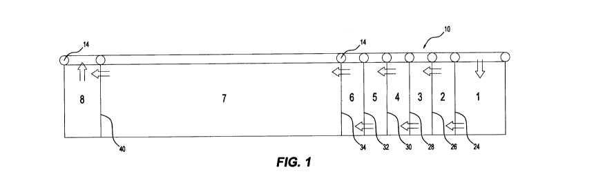
Referring firstly to Figs. 1 and 2, the treatment pit 10 is preferably
manufactured
from polypropylene, more preferably reinforced 1.1mm polypropylene, although
any other suitable material may be used. In this embodiment, the pit is an
elongated rectangle in plan, and has a V-shaped base 12 (Figs. 4, 5 and 6).
Obviously, the pit could be any shape, and have a base of any suitable
configuration.
The pit 10 may be positioned in a depression or the like adjacent to a body of
water, or arranged to float on the body of water. In the first alternative,
the pit 10
may not require any supporting means for the material of the pit 10, as the
material of the depression may take the place of such supporting means which
may be required in the second, floating, alternative arrangement. One such
depression may be a watercourse of a river or stream, where the pit 10 may
treat
water in that river or stream. In the second alternative, as shown in Figs. 1
and 2,
floats 14 may be constructed from a tube bladder which may be inserted into an
envelope (not shown) manufactured into the top of the pit 10 sides and chamber
(to be described hereinafter) tops. These floats 14 provide flotation and
rigidity to
the structure of pit 10. It also provides a double layer of material for
puncture
protection for the pit 10 and further rigidity. It makes bladder replacement
easier
CA 02802774 2012-12-14
WO 2012/000019 PCT/AU2011/000785
4
with such an arrangement. Other solid or flexible float means may be employed.
The float chamber may be built into the structure of pit 10 without the
requirement
for an internal bladder. The float mechanism may alternatively be formed from
rigid pipe or an equivalent structure.
The sides 16, 18 (Figs. 4, 5 and 6) of the pit 10 may be held together (to
stop
expansion and bellowing) with rope (not shown) attached to the insides of the
pit
along its length at spacing of preferably approximately' to 3/ its width.
Alternatively, the sides 16, 18 could be held together by mesh, somewhat like
the
orange safety mesh used as a barrier at road works. The advantage of using
mesh would be that apart from holding the sides 16, 18 together, it may act to
further mix water as it passes along the length of pit 10, in a manner to be
described hereinafter. There are different types of mesh envisaged for this
embodiment. Some types have large apertures, and some have small apertures.
Different types of mesh may be matched to the treatment and mixing required
relative to aperture size and flow rates. This may also assist in providing
laminar
flow, and therefore better settling of floc.
The pit 10 may have one or more treatment chambers. In the present
embodiment, the pit 10 has eight chambers, numbered from 1 to 8. As best
shown in Figs. 4, 5 and 6, the cross-sectional profile of the pit 10 includes
vertical
(in use) sides 16, 18 at the top of pit 10, with inwardly sloping sides 20, 22
below
side walls 16, 18. An alternative for pit 10 may involve the use of inwardly
sloping
sides, such as sides 20, 22, only.
Chamber 1, as shown by way of preference, is larger than chambers 2 to 6
inclusive, each of which is preferably approximately the same size. Chamber 7
is
the largest chamber, preferably, and chamber 8 is, by way of preference, about
the same size as chamber 1. Chamber 7, which as will be described hereinafter
as a flocculation chamber, need not be as large as shown. Alternatively, it
may
need, for a specific task, to be larger than shown. The size of each of the
chambers 1 to 8 may be adjusted to suit requirements.
CA 02802774 2012-12-14
WO 2012/000019 PCT/AU2011/000785
There are walls 24, 26, 28, 30, 32 and 34 separating chambers 1 and 2, 2 and
3, 3
and 4, 4 and 5, 5 and 6 and 6 and 7, respectively. Turning now to Fig. 5, wall
24 is
shown. In this preferred embodiment, walls 28 and 32 would be at least
substantially the same as wall 24. Apertures 36 are located in wall 24. The
5 apertures 36 may take any number, form or shape, and may be arranged in any
pattern. As shown by way of preferment, apertures 36 are located near the V-
shaped base of pit 10.
Fig. 4 shows wall 26. In this preferred embodiment, walls 30, 34 and 40 would
be
at least substantially the same as wall 26. Apertures 38 are located in wall
26.
The apertures 38 may take any number, form or shape, and may be arranged in
any pattern. As shown by way of preferment, apertures 38 are located near the
top of pit 10.
It can be seen from the horizontal arrows in Fig. 1 that walls of the type of
wall 24
and wall 26 are staggered along the length of pit 10. A "high aperture" wall
such
as 26 has "low aperture" walls 24 and 28 before and after it, in the direction
of the
arrows in Fig. 1, and this pattern is repeated for walls 30, 32 and 34. Wall
40, (not
shown in detail) is at least substantially the same as wall 26, 30 34, and
separates
chambers 7 and 8.
The pit 10 operates as follows. Contaminated water is supplied from the body
of
water or from an external source to chamber 1, preferably by being pumped into
that chamber. This allows stabilization of turbulent inflow water in chamber
1, and
initial mixing of reagents with the water if the reagents are injected into
the water in
chamber 1 at this stage.
The water and reagent mix then travels down chamber 1, from right to left in
Fig. 1,
and passes through apertures 36 at the base 12 of wall 24 into chamber 2.
The water then flows upwards within the next chamber, chamber 2, to then pass
through apertures 38 at the top of wall 26 into chamber 3, just below floats
14.
Different reagents may be injected into each of chambers 1,2,3,4,5 or 6. As
required by the particular treatment process, or for any other reason.
CA 02802774 2012-12-14
WO 2012/000019 PCT/AU2011/000785
6
The water continues to flow through chambers 1, 2, 3, 4, 5 and 6, alternately
flowing through lower apertures 36, then upwards to flow through apertures 38,
then downwards, and so on, providing a mixing facility for water and reagent
before it enters chamber 7. The spacing of these first few mixing chambers of
chambers 1 to 8 and the size of apertures 36, 38 decides the aggressiveness of
mixing. Other types of static or moving mixers may be placed in the apertures
36,
38 or in other places where liquid flow occurs, or to induce the flow of
liquid.
Single or several mixers in apertures 36, 38 may be utilised.
Once in chamber 7 the water and floc is allowed to stabilize and create
laminar
flow, which allows the floc to settle out at the bottom 12 of the pit 10.
As the water travels through chamber 7 the floc separates and settles to the
bottom 12 so that the clean treated water can exit chamber 7 at the top
through
apertures in wall 40 (not shown, but being but similar to apertures 38 in Fig.
4, but
preferably not being located as high in wall 40 as apertures 38 in walls 26,
30 and
34) just below the floats 12. The clean treated water enters chamber 8 from
which
it may be discharged to the body of water, for example by being pumped out, or
the clean treated water may be pumped to an external location, such as a dam,
tank or reservoir.
Figs. 3 and 6 show the arrangement in pit 10 for the extraction of floc. The
floc is
extracted from the pit 10 system via a longitudinal pipe 42 placed at the
bottom of
the "V" (12) in the pit 10. This floc extraction pipe 42 is divided into
sections of
about '/3 to 'h of the width of the pit 10. The pipe 42 has holes 44 drilled
along its
length at calibrated lengths to extract the floc. Each of these sections of
pipe 44
has a vertical extraction pipe 46 which lays along the side of the pit 10 to
near the
float 12 on one side: see Fig. 6.
Alternatively, the combination of the vertical floc extraction pipes 42 and
valves
could be omitted. The floc could be extracted lengthways through'the floc
extraction pipe 42 using no valves, and requiring calibrated apertures in the
lower
floc pipe to regulate the floc extraction rate in different areas of pit 10.
CA 02802774 2012-12-14
WO 2012/000019 PCT/AU2011/000785
7
By way of an example, for a pit that is about 45 metres long by about 7 metres
wide, this pit embodiment may have eight to fifteen longitudinal floc
extraction pipe
sections with eight to fifteen corresponding vertical extraction pipes 46
feeding
into one header pipe 48. Each of these pipes 46 has a valve 50 at the top just
before the pipes 46 enter the header pipe 48, which is connected to a pump
(not
shown). By way of preference, pipe sections 46 may be located only in chamber
7, although they may also be located in one or more of chambers 1 to 6.
Header pipe 48 collects the floc from each of the base pipes 46 at a pre
adjusted
rate, utilizing valves. The floc may then be disposed of or recycled through
the
process to provide better reagent usage, contaminant extraction and floc
density.
The volume of water in the chambers 1 to 8, and therefore the level at which
the
floats 12 sit in the water is preferably adjustable by a level sensor (not
shown)
attached to the side of the pit 10. This level sensor either changes the input
or
output pump speeds or opens and closes a valve to release more or less water
from the final chamber, chamber 8. As the pit 10 sinks, the sensor slows the
input
pumps (or increases the speeds of the output pumps) or opens an exit valve.
This
keeps a constant volume in the pit 10 and therefore keeps the pit 10 at a
constant
level in the water. Another sensor could be associated with the previously
described means to hold the sides 16, 18 of the pit 10 together. Sensing
means,
such as a float, associated with a rope, mesh or the like, may respond to
sideways
pressure on sides 16, 18, translated to tightening or loosening of the rope or
mesh,
as a result of increased water within pit 10. The sensing means could, having
detected this situation, then adjust pump rates or the like to restore the pit
10 to a
more desired status.
The upper apertures 38 may be associated with a vertical (in use) pipe (not
shown) on the upstream side, which bends through 90 and passes through the
associated wall. The upper level of this pipe may be used to establish the
water
level, and thus the water in each of chamber 1 to 8. This may act like a weir.
The pit 10 is adapted to be fully floating by itself and may be secured in
place in
the body of water, such as a dam, reservoir, lake or river, by ropes or using
other
CA 02802774 2012-12-14
WO 2012/000019 PCT/AU2011/000785
8
methods. Alternative arrangements may include locating the pit 10 in a dam,
where it takes water from the dam and the resulting treated water is pumped
elsewhere. Or the pit 10 may be located in a dam, and the contaminated water
is
pumped from elsewhere into pit 10 and the treated water is released into the
dam.
Another alternative is to locate a pit 10 in a dam, and to pump contaminated
water
from elsewhere into pit 10, and the treated water pumped to another location.
Two or more pits 10 may be connected together in series to provide multiple
processing, or may be placed parallel to one another to double the volume
treatable or to double the treatment rate. If different designs of pits 10 are
connected together in series they are able to provide different types of water
processing. For example, first stage pH adjustment, second stage flocculation
requiring different mixing aggressiveness, third stage, metal removal, and
possibly
a final stage for activated carbon polishing. A large pit 10 of this design
without
chambers could also be used for storage of treated water.
It may be a preferment or alternative for a pit 10 to be constructed in a
modular
arrangement. For example, groups of chambers, such as, say, chambers land 2,
chambers 3, 4, 5 and 6, chamber 7 and so on, could be manufactured as separate
units. This may make manufacture, storage, installation and repair easier, as
well
as allowing different use sections to be matched to different treatment
requirements, and providing general flexibility. For example, one type of
treatment
may require two units of chamber 3, 4, 5 and 6.
The units may be bolted together along each vertical wall (such as walls 24
and
26). This may be effected using plastic bolts (not shown) though punched
eyelets
(also not shown). This modular arrangement would result in a double wall where
one unit is secured to an adjacent unit, adding to the material used, compared
to a
pit 10 constructed in one piece, but the benefits would, it is believed,
greatly
outweigh the costs. The apertures 36, 38 would have to be aligned when the end
wall of one unit is secured to the end wall of a second unit, to allow free
flow of
water from the chamber one side of the joined units to the chamber of the
other
side of the connecting walls.
CA 02802774 2012-12-14
WO 2012/000019 PCT/AU2011/000785
9
This method utilizes a water body to contain the treatment pits 10 thereby
minimizing time for installation and room required. The pits 10 may be self-
supporting, in that their design holds them to shape when full, or, can be
built
around and internal or external frame or brace, or may be held in place and
shape
by connecting to the bottom, bank or other structure. Pits 10 design may also
be
constructed in-ground without the float supporting structure.
This design of pits 10 described herein may be used in any manner in which
water
requires holding, holding for treatment or continual processing. This includes
chemical treatment, chemical precipitation, electro coagulation,
sterilization,
filtering, ion exchange, and so on. These systems can be set up to provide
single,
dual or multiple process water treatment where the water transfers from one
pit 10
to the next to have the same or a totally different process applied to it, or
the water
may be batch treated in the pit or pits 10.
There are many different applications for the system described herein. It may
be
installed into a dam or lake or a depression in the ground to contain
contaminated
water within the larger water body, or it could contain treated water storage
in the
larger body of water. It could be located in the watercourse (river bed) of a
flowing
river or stream to treat water from that river or stream, or may treat water
from
another source for discharge into the river or stream, or to another location.
It
could contain fresh water in a salty or other environment.
There are many different contaminated water situations that the pit 10 system
of
this invention could be used for. Drinking water treatment, water treatment
for
industry, acid mine drainage treatment, treatment in which chemicals are added
prior to use elsewhere, are examples. It could also be used to store a fluid
in
another fluid environment. The system of this invention may be placed in a
body of
water such as a dam, which contains clean water. Contaminated water could be
brought into the pit 10 from another source and treated water discharged into
the
body of water or to another location.
Any combination of location, source of contaminated water and discharge
location
may be used. For example, contaminated water may be pumped from a mineshaft
CA 02802774 2012-12-14
WO 2012/000019 PCT/AU2011/000785
into a pit 10 floating in a body of water, treated, and then discharged into
the body
of water, or to another location. By way of a preference, the pumps used to
move
water into and out of the pit 10 and within pit 10 may be centrifugal pumps or
axial
flow pumps locatable on or in one or more of chambers 1 through 8.
5
The entire contents of the specification and drawings of Australian
provisional
patent application no. 2010902882 filed on 30 June 2011 are herewith
incorporated into this specification.