Note: Descriptions are shown in the official language in which they were submitted.
CA 02802786 2012-12-14
WO 2012/001381 PCT/GB2011/051037
1
Improvements in or relating to Ophthalmology
The present invention relates to an apparatus and method for illuminating,
imaging and treating the retina of a human eye.
Imaging systems, such as scanning laser ophthalmoscopes (SLOB), may
comprise a large number of optical components, such as laser scanning
elements, scan transfer mirrors, laser sources and detectors. The laser
scanning arrangement consists of first and second orthogonal scanning
elements, which typically include a high speed rotating polygonal mirror
and a motor driven slow speed mirror. These elements are used to create
a raster scan pattern of the human retina. The polygon mirror has a
plurality of facets and typically provides the vertical scanning of the laser
beam, and the slow speed mirror typically provides the horizontal scanning
of the laser beam. The scan transfer mirror transfers the two dimensional
laser scan pattern created by the scanning elements to the retina of the
eye.
While such imaging systems provide acceptable images of the retina of
the eye, they are limited in that they are expensive to manufacture (the
laser scanning elements and scan transfer mirror are particularly
expensive components), large in size and, due to the large number of
optical components, have low optical efficiency.
According to a first aspect of the present invention there is provided an
apparatus for illuminating the retina of an eye comprising:
an illuminating device including a planar light source capable of
producing light in a plane, such that the illuminating device is capable of
illuminating a circumferential line on the retina; and
CA 02802786 2012-12-14
WO 2012/001381 PCT/GB2011/051037
2
a support structure;
wherein the illuminating device is pivotably mountable to the
support structure and is rotatable about an axis which lies substantially on
the plane defined by the light source, such that, in use, the illuminating
device may be rotated about the axis to illuminate an area of the retina.
The axis of rotation of the illuminating device may be located around the
pupillary point of the eye. The axis of rotation of the illuminating device
may be coincident with the front nodal point of the eye.
The axis of rotation of the illuminating device may lie on a horizontal plane
defined by the optical axis of the eye. Alternatively, the axis of rotation of
the illuminating device may be perpendicular to the horizontal plane
defined by the optical axis of the eye. Alternatively, the axis of rotation of
the illuminating device may not be parallel or perpendicular to the
horizontal plane defined by the optical axis of the eye. In all of these
arrangements, the axis of rotation of the illuminating device should lie on
the plane defined by the light source.
The illuminating device may be configured such that its rotation about the
axis is automated. The rotation of the imaging device may be computer-
controlled.
The illuminating device may be configured to illuminate the retina by
scanning collimated light across the retina of the eye. The illuminating
device may therefore be capable of performing a one-dimensional scan of
collimated light across the retina of the eye.
The axis of rotation of the illuminating device may be parallel to a plane
defined by the one-dimensional collimated light scan produced by the
CA 02802786 2012-12-14
WO 2012/001381 PCT/GB2011/051037
3
illuminating device. That is, the plane of the axis of rotation of the
illuminating device may be orthogonal to the plane defined by the one-
dimensional collimated light scan it creates.
The rotational axis of the illuminating device may lie on the plane defined
by the one-dimensional collimated light scan produced by the illuminating
device.
The illuminating device may comprise:
a source of collimated light; and
a scanning element,
wherein the source of collimated light and the scanning element combine
to provide a one-dimensional collimated light scan from a point; and
the illuminating device further comprises a scan transfer device,
wherein the scan transfer device has two foci and the point is provided at
a first focus of the scan transfer device and the pupillary point of the eye
is
accommodated at a second focus of the scan transfer device, and wherein
the scan transfer device transfers the one-dimensional collimated light
scan from the point into the eye.
The front nodal point of the eye may be accommodated at the second
focus of the scan transfer device.
The scanning element may be an oscillating mechanism.
The scanning element may be an oscillating mirror, such as an oscillating
plane mirror.
The scanning element may be a resonant scanner.
CA 02802786 2012-12-14
WO 2012/001381 PCT/GB2011/051037
4
The scanning element may be a resonant mirror, such as a resonant
scanning mirror.
The scanning element may be a microelectromechanical system (MEMS)
scanning element. The MEMS scanning element may be a one-
dimensional scanning element or a two-dimensional scanning element.
The scan transfer device may comprise a tilted spherical mirror, an
aspherical mirror, an elliptical mirror, an ellipsoidal mirror, a pair of
parabola mirrors, a pair of paraboloidal mirrors or a lens system. In the
case where the scan transfer device comprises a lens system, the lens
system is arranged to provide two foci.
The source of collimated light may be a laser, a light emitting diode (LED),
a Vertical Cavity Surface Emitting Laser (VCSEL), a super luminescent
diode, a diode laser or a collimated incandescent lamp.
The source of collimated light may include one or more light sources. The
source of collimated light may include one or more lasers, light emitting
diodes (LEDs), Vertical Cavity Surface Emitting Lasers (VCSELs), super
luminescent diodes, diode lasers or collimated incandescent lamps.
The source of collimated light may include one or more light sources of
differing wavelengths.
The illuminating device may further comprise one or more detectors for
detecting the reflected collimated light from the retina.
The source of collimated light may be located with the illuminating device,
such that it rotates with the illuminating device.
CA 02802786 2012-12-14
WO 2012/001381 PCT/GB2011/051037
The one or more detectors may be located with the illuminating device,
such that they rotate with the illuminating device.
5 The source of collimated light may be located remotely from the
illuminating device and the collimated light may be transmitted to the
illuminating device by fibre optic, or the like.
The one or more detectors may be located remotely from the illuminating
device and the reflected collimated light may be transmitted from the
illuminating device by fibre optic, or the like.
The illuminating device may be capable of illuminating an area of the
retina. That is, the illuminating device may be capable of illuminating a
two-dimensional portion of the retina.
The scanning element may be a microelectromechanical systems (MEMS)
scanning element. The MEMS scanning element may be a two-
dimensional scanning element.
The illuminating device may be configured to illuminate the circumferential
line on the retina by manipulating light from a source of light to produce a
plurality of light beams which illuminate the retina of the eye. The plurality
of light beams form a plane of light which illuminates the retina. The
illuminating device may manipulate light from the source of light by
passing the light through a line generating element such as a cylindrical
lens, toroidal lens or gradient refractive index lens. That is, the
illuminating device may be capable of manipulating light from the source of
light by passing the light through a line generating element, or the like, to
produce a plurality of light beams which illuminate the retina of the eye.
CA 02802786 2012-12-14
WO 2012/001381 PCT/GB2011/051037
6
The illuminating device may be configured to illuminate the circumferential
line on the retina by manipulating light from a source of collimated light to
produce a plurality of collimated light beams which illuminate the retina of
the eye. The plurality of collimated light beams form a plane of collimated
light which illuminates the retina. The illuminating device may manipulate
light from the source of collimated light by passing the light through a line
generating element such as a cylindrical lens, toroidal lens or gradient
refractive index lens. That is, the illuminating device may be capable of
manipulating light from the source of collimated light by passing the
collimated light through a line generating element, or the like, to produce a
plurality of collimated light beams which illuminate the retina of the eye. In
this arrangement light from the source of collimated light is manipulated
such that the light is collimated in one dimension and divergent in another
dimension.
The axis of rotation of the illuminating device may be parallel to a plane
defined by the plurality of light beams produced by the illuminating device.
That is, the plane of the axis of rotation of the illuminating device may be
orthogonal to the plane of light beams produced by the illuminating device.
The axis of rotation of the illuminating device may lie on the plane defined
by the plurality of light beams produced by the illuminating device.
The axis of rotation of the illuminating device may be parallel to a plane
defined by the plurality of collimated light beams produced by the
illuminating device. That is, the plane of the axis of rotation of the
illuminating device may be orthogonal to the plane of collimated light
beams produced by the illuminating device.
CA 02802786 2012-12-14
WO 2012/001381 PCT/GB2011/051037
7
The illuminating device may comprise:
a source of light; and
a light manipulating element,
wherein the source of light and the light manipulating element combine to
provide a plurality of light beams from a point; and
the illuminating device further comprises a scan transfer device,
wherein the scan transfer device has two foci and the point is provided at
a first focus of the scan transfer device and the pupillary point of the eye
is
accommodated at a second focus of the scan transfer device, and wherein
the scan transfer device transfers the plurality of light beams from the
point into the eye.
The source of light may provide collimated light. That is, the illuminating
device may comprise a source of collimated light.
The light manipulating element may be a collimated light manipulating
element.
The light manipulating element may be a line generating element. The
line generating element may be a cylindrical lens, toroidal lens or gradient
refractive index lens.
The collimated light manipulating element may be a line generating
element. The line generating element may be a cylindrical lens, toroidal
lens or gradient refractive index lens.
The scan transfer device may comprise a tilted spherical mirror, an
aspherical mirror, an elliptical mirror, an ellipsoidal mirror, a pair of
parabola mirrors, a pair of paraboloidal mirrors or a lens system. In the
CA 02802786 2012-12-14
WO 2012/001381 PCT/GB2011/051037
8
case where the scan transfer device comprises a lens system, the lens
system is arranged to provide two foci.
The front nodal point of the eye may be accommodated at the second
focus of the scan transfer device.
The source of light may include a diverging laser diode and a toroidal lens
or a lamp source with a slit aperture.
The source of collimated light may be a laser, a light emitting diode (LED),
a Vertical Cavity Surface Emitting Laser (VCSEL), a super luminescent
diode, a diode laser or a collimated incandescent lamp.
The source of collimated light may comprise one or more light sources.
Alternatively, the source of collimated light may comprise one or more
lasers, light emitting diodes (LEDs), Vertical Cavity Surface Emitting
Lasers (VCSELs), super luminescent diodes, diode lasers or collimated
incandescent lamps.
The source of light may include one or more light sources of differing
wavelengths.
The source of collimated light may include one or more light sources of
differing wavelengths.
The illuminating device may further comprise one or more detectors for
detecting the reflected light from the retina.
The illuminating device may further comprise one or more detectors for
detecting the reflected collimated light from the retina.
CA 02802786 2012-12-14
WO 2012/001381 PCT/GB2011/051037
9
The source of light may be located with the illuminating device, such that it
rotates with the illuminating device.
The source of collimated light may be located with the illuminating device,
such that it rotates with the illuminating device.
The one or more detectors may be located with the illuminating device,
such that they rotate with the illuminating device.
The source of light may be located remotely from the illuminating device
and the light may be transmitted to the illuminating device by fibre optic, or
the like.
The source of collimated light may be located remotely from the
illuminating device and the collimated light may be transmitted to the
illuminating device by fibre optic, or the like.
The illuminating device may be capable of illuminating an area of the
retina. That is, the illuminating device may be capable of illuminating two-
dimensional portion of the retina.
The illuminating device of the apparatus may be pivotable between a first
position, in which the illuminating device may be used to illuminate a two-
dimensional portion of the first retina of a first eye, and a second position,
in which the illuminating device may be used to illuminate a two-
dimensional portion of the second retina of a second eye.
The pivoting axis of the illuminating device may be orthogonal to the
rotational axis of the illuminating device.
CA 02802786 2012-12-14
WO 2012/001381 PCT/GB2011/051037
The apparatus may comprise two illuminating devices, wherein each
illuminating device may be capable of illuminating a circumferential line on
the retina and may be rotatable about an axis which lies substantially on
5 the plane defined by the light source. The illuminating devices may be
rotated together or separately. The illuminating devices may be located in
a single housing, or located separately in two separate housings.
The illuminating devices are configured such that the circumferential lines
10 on the retina illuminated by each device are in the same direction. That
is, the circumferential lines illuminated by each device are parallel.
According to a second aspect of the present invention there is provided a
system for illuminating the retina of each eye of a patient comprising two
apparatuses according to the first aspect of the present invention, wherein
each apparatus may be capable of illuminating the retina of one eye.
According to a third aspect of the present invention there is provided a
method of illuminating the retina of an eye with collimated light comprising
the steps of:
providing an illuminating device including a planar light source
capable of producing light in a plane, such that the illuminating device is
capable of illuminating a circumferential line on the retina;
providing a support structure,
wherein the illuminating device is pivotably mountable to the
support structure and is rotatable about an axis which lies substantially on
the plane defined by the light source; and
rotating the illuminating device about the axis to illuminate a
plurality of circumferential lines on the retina with collimated light.
CA 02802786 2012-12-14
WO 2012/001381 PCT/GB2011/051037
11
The axis of rotation of the illuminating device may lie on a horizontal plane
defined by the optical axis of the eye. Alternatively, the axis of rotation of
the illuminating device may be perpendicular to the horizontal plane
defined by the optical axis of the eye. Alternatively, the axis of rotation of
the illuminating device may not be parallel or perpendicular to the
horizontal plane defined by the optical axis of the eye. In all of these
arrangements, the axis of rotation of the illuminating device should lie on
the plane defined by the light source.
The illuminating device may be configured such that its rotation about the
axis is automated. The rotation of the imaging device may be computer-
controlled.
According to a fourth aspect of the present invention there is provided an
apparatus for imaging the retina of an eye comprising:
an imaging device capable of obtaining a substantially one-
dimensional image of the retina; and
a support structure;
wherein the imaging device is pivotably mounted to the support
structure and is rotatable about an axis which is parallel to the direction of
the substantially one-dimensional image, such that, in use, the imaging
device may be rotated about the axis to obtain a plurality of substantially
one-dimensional images of the retina, which may be combined to obtain a
two-dimensional image of the retina.
The substantially one-dimensional image of the retina obtained by the
imaging device is considered here to be an image having a length which is
many times greater than its width. The direction of the substantially one-
dimensional image is considered to be in the same direction as the length
of the image.
CA 02802786 2012-12-14
WO 2012/001381 PCT/GB2011/051037
12
The axis of rotation of the imaging device may be located around the
pupillary point of the eye. The axis of rotation of the imaging device may
be coincident with the front nodal point of the eye.
The axis of rotation of the imaging device may lie on a horizontal plane
defined by the optical axis of the eye. Alternatively, the axis of rotation of
the imaging device may be perpendicular to the horizontal plane defined
by the optical axis of the eye. Alternatively, the axis of rotation of the
imaging device may not be parallel or perpendicular to the horizontal plane
defined by the optical axis of the eye. In all of these arrangements, the
axis of rotation of the imaging device should remain parallel to the
direction of the substantially one-dimensional image.
The imaging device may be configured such that its rotation about the axis
is automated. The rotation of the imaging device may be computer-
controlled.
The imaging device may be configured to obtain the substantially one-
dimensional image of the retina by scanning collimated light across the
retina of the eye. The imaging device may therefore be capable of
performing a one-dimensional scan of collimated light across the retina of
the eye.
The axis of rotation of the imaging device may be parallel to a plane
defined by the substantially one-dimensional image collimated light scan
produced by the imaging device. That is, the plane of the axis of rotation
of the imaging device may be orthogonal to the plane defined by the one-
dimensional collimated light scan it creates.
CA 02802786 2012-12-14
WO 2012/001381 PCT/GB2011/051037
13
The axis of rotation of the imaging device may lie on the plane defined by
the one-dimensional collimated light scan produced by the imaging device.
The imaging device may comprise:
a source of collimated light; and
a scanning element,
wherein the source of collimated light and the scanning element combine
to provide a one-dimensional collimated light scan from a point; and
the imaging device further comprises a scan transfer device,
wherein the scan transfer device has two foci and the point is provided at
a first focus of the scan transfer device and the pupillary point of the eye
is
accommodated at a second focus of the scan transfer device, and wherein
the scan transfer device transfers the one-dimensional collimated light
scan from the point into the eye.
The front nodal point of the eye may be accommodated at the second
focus of the scan transfer device.
The scanning element may be an oscillating mechanism.
The scanning element may be an oscillating mirror, such as an oscillating
plane mirror.
The scanning element may be a resonant scanner.
The scanning element may be a resonant mirror, such as a resonant
scanning mirror.
CA 02802786 2012-12-14
WO 2012/001381 PCT/GB2011/051037
14
The scanning element may be a microelectromechanical system (MEMS)
scanning element. The MEMS scanning element may be a one-
dimensional scanning element or a two-dimensional scanning element.
The scan transfer device may comprise a tilted spherical mirror, an
aspherical mirror, an elliptical mirror, an ellipsoidal mirror, a pair of
parabola mirrors, a pair of paraboloidal mirrors or a lens system. In the
case where the scan transfer device comprises a lens system, the lens
system is arranged to provide two foci.
The source of collimated light may be a laser, a light emitting diode (LED),
a Vertical Cavity Surface Emitting Laser (VCSEL), a super luminescent
diode, a diode laser or a collimated incandescent lamp.
The source of collimated light may include one or more light sources. The
source of collimated light may include one or more lasers, light emitting
diodes (LEDs), Vertical Cavity Surface Emitting Lasers (VCSELs), super
luminescent diodes, diode lasers or collimated incandescent lamps.
The source of collimated light may include one or more light sources of
differing wavelengths.
The imaging device may further comprise one or more detectors for
detecting the reflected collimated light from the retina.
The source of collimated light may be located with the imaging device,
such that it rotates with the imaging device.
The one or more detectors may be located with the imaging device, such
that they rotate with the imaging device.
CA 02802786 2012-12-14
WO 2012/001381 PCT/GB2011/051037
The source of collimated light may be located remotely from the imaging
device and the collimated light may be transmitted to the imaging device
by fibre optic, or the like.
5
The one or more detectors may be located remotely from the imaging
device and the reflected collimated light may be transmitted from the
imaging device by fibre optic, or the like.
10 The imaging device may be capable of obtaining a two-dimensional image
of the retina. Therefore, in use, the imaging device may be rotated about
the axis to obtain a plurality of two-dimensional images of the retina. The
plurality of two-dimensional images may be combined to obtain a larger
two-dimensional image of the retina. That is, the plurality of two-
15 dimensional images may produce a montage two-dimensional image of
the retina. In this arrangement, the plurality of two-dimensional images
may be "stitched" to form a larger two-dimensional image of the retina.
Alternatively, the plurality of two-dimensional images may be arranged to
overlap in the direction of rotation of the imaging device. The plurality of
overlapping two-dimensional images of the retina may be "stitched" to
form the montage two-dimensional image of the retina.
The scanning element may be a microelectromechanical systems (MEMS)
scanning element. The MEMS scanning element may be a two-
dimensional scanning element.
The imaging device may be configured to obtain the substantially one-
dimensional image of the retina by manipulating a source of light to
produce a plurality of light beams which illuminate the retina of the eye.
The plurality of light beams form a plane of light which illuminates the
CA 02802786 2012-12-14
WO 2012/001381 PCT/GB2011/051037
16
retina. The imaging device may manipulate the source of light by passing
the light through a line generating element such as a cylindrical lens,
toroidal lens or gradient refractive index lens. That is, the imaging device
may be capable of manipulating the source of light by passing the light
through a line generating element, or the like, to produce a plurality of
light
beams which illuminate the retina of the eye.
The imaging device may be configured to obtain the substantially one-
dimensional image of the retina by manipulating a source of collimated
light to produce a plurality of collimated light beams which illuminate the
retina of the eye. The plurality of collimated light beams form a plane of
collimated light which illuminates the retina. The imaging device may
manipulate the source of collimated light by passing the light through a line
generating element such as a cylindrical lens, toroidal lens or gradient
refractive index lens. That is, the imaging device may be capable of
manipulating the source of collimated light by passing the collimated light
through a line generating element, or the like, to produce a plurality of
collimated light beams which illuminate the retina of the eye. In this
arrangement the source of collimated light is manipulated such that the
light is collimated in one dimension and divergent in another dimension.
The axis of rotation of the imaging device may be parallel to a plane
defined by the plurality of light beams produced by the imaging device.
That is, the plane of the axis of rotation of the imaging device may be
orthogonal to the plane of light beams produced by the imaging device.
The axis of rotation of the imaging device may be parallel to a plane
defined by the plurality of collimated light beams produced by the imaging
device. That is, the plane of the axis of rotation of the imaging device may
CA 02802786 2012-12-14
WO 2012/001381 PCT/GB2011/051037
17
be orthogonal to the plane of collimated light beams produced by the
imaging device.
The axis of rotation of the imaging device may lie on the plane defined by
the plurality of light beams produced by the imaging device.
The imaging device may comprise:
a source of light; and
a light manipulating element,
wherein the source of light and the light manipulating element combine to
provide a plurality of light beams from a point; and
the imaging device further comprises a scan transfer device,
wherein the scan transfer device has two foci and the point is provided at
a first focus of the scan transfer device and the pupillary point of the eye
is
accommodated at a second focus of the scan transfer device, and wherein
the scan transfer device transfers the plurality of light beams from the
point into the eye.
The source of light may provide collimated light. That is, the imaging
device may comprise a source of collimated light.
The light manipulating element may be a collimated light manipulating
element.
The light manipulating element may be a line generating element. The
line generating element may be a cylindrical lens, toroidal lens or gradient
refractive index lens.
CA 02802786 2012-12-14
WO 2012/001381 PCT/GB2011/051037
18
The collimated light manipulating element may be a line generating
element. The line generating element may be a cylindrical lens, toroidal
lens or gradient refractive index lens.
The scan transfer device may comprise a tilted spherical mirror, an
aspherical mirror, an elliptical mirror, an ellipsoidal mirror, a pair of
parabola mirrors, a pair of paraboloidal mirrors or a lens system. In the
case where the scan transfer device comprises a lens system, the lens
system is arranged to provide two foci.
The front nodal point of the eye may be accommodated at the second
focus of the scan transfer device.
The source of light may include a diverging laser diode and a toroidal lens
or a lamp source with a slit aperture.
The source of collimated light may be a laser, a light emitting diode (LED),
a Vertical Cavity Surface Emitting Laser (VCSEL), a super luminescent
diode, a diode laser or a collimated incandescent lamp.
The source of collimated light may comprise one or more light sources.
Alternatively, the source of collimated light may comprise one or more
lasers, light emitting diodes (LEDs), Vertical Cavity Surface Emitting
Lasers (VCSELs), super luminescent diodes, diode lasers or collimated
incandescent lamps.
The source of light may include one or more light sources of differing
wavelengths.
CA 02802786 2012-12-14
WO 2012/001381 PCT/GB2011/051037
19
The source of collimated light may include one or more light sources of
differing wavelengths.
The imaging device may further comprise one or more detectors for
detecting the reflected light from the retina.
The imaging device may further comprise one or more detectors for
detecting the reflected collimated light from the retina.
The source of light may be located with the imaging device, such that it
rotates with the imaging device.
The source of collimated light may be located with the imaging device,
such that it rotates with the imaging device.
The one or more detectors may be located with the imaging device, such
that they rotate with the imaging device.
The source of light may be located remotely from the imaging device and
the light may be transmitted to the imaging device by fibre optic, or the
like.
The source of collimated light may be located remotely from the imaging
device and the collimated light may be transmitted to the imaging device
by fibre optic, or the like.
The imaging device may be capable of obtaining a two-dimensional image
of the retina. Therefore, in use, the imaging device may be rotated about
the axis to obtain a plurality of two-dimensional images of the retina. The
plurality of two-dimensional images may be combined to obtain a larger
CA 02802786 2012-12-14
WO 2012/001381 PCT/GB2011/051037
two-dimensional image of the retina. That is, the plurality of two-
dimensional images may produce a montage two-dimensional image of
the retina. In this arrangement, the plurality of two-dimensional images
may be "stitched" to form a larger two-dimensional image of the retina.
5 Alternatively, the plurality of two-dimensional images may be arranged to
overlap in the direction of rotation of the imaging device. The plurality of
overlapping two-dimensional images of the retina may be "stitched" to
form the montage two-dimensional image of the retina.
10 The imaging device of the apparatus may be pivotable between a first
position, in which the imaging device may be used to obtain a two-
dimensional image of the first retina of a first eye, and a second position,
in which the imaging device may be used to obtain a two-dimensional
image of the second retina of a second eye.
The pivoting axis of the imaging device may be orthogonal to the rotational
axis of the imaging device.
The apparatus may comprise two imaging devices, wherein each imaging
device may be capable of obtaining a substantially one-dimensional image
of the retina and may be rotatable about an axis which is parallel to the
direction of the substantially one-dimensional image. The imaging devices
may be rotated together or separately. The imaging devices may be
located in a single housing, or located separately in two separate
housings.
The imaging devices are configured such that the substantially one-
dimensional images obtained by each device are in the same direction.
That is, the substantially one-dimensional images obtained by each device
are parallel.
CA 02802786 2012-12-14
WO 2012/001381 PCT/GB2011/051037
21
The apparatus may further comprise one or more data processing devices
for storing the plurality of at least one-dimensional images and/or
combining the images to obtain the two-dimensional image.
According to a fifth aspect of the present invention there is provided a
method of imaging the retina of an eye comprising the steps of:
providing an imaging device capable of obtaining a substantially
one-dimensional image of the retina, wherein the imaging device is
rotatable about an axis which is parallel to the direction of the
substantially
one-dimensional image;
providing a support structure;
wherein the imaging device is pivotably mountable to the support
structure;
rotating the imaging device about the axis to obtain a plurality of
substantially one-dimensional images of the retina; and
combining the plurality of substantially one-dimensional images to
obtain a two-dimensional image of the retina.
The axis of rotation of the imaging device may lie on a horizontal plane
defined by the optical axis of the eye. Alternatively, the axis of rotation of
the imaging device may be perpendicular to the horizontal plane defined
by the optical axis of the eye. Alternatively, the axis of rotation of the
imaging device may not be parallel or perpendicular to the horizontal plane
defined by the optical axis of the eye. In all of these arrangements, the
axis of rotation of the imaging device should remain parallel to the
direction of the substantially one-dimensional image.
CA 02802786 2012-12-14
WO 2012/001381 PCT/GB2011/051037
22
The imaging device may be configured such that its rotation about the axis
is automated. The rotation of the imaging device may be computer-
controlled.
According to a sixth aspect of the present invention there is provided an
apparatus for treating the retina of an eye with collimated light comprising:
an illuminating device including a planar light source capable of
producing light in a plane, such that the illuminating device is capable of
illuminating a circumferential line on the retina; and
a support structure;
wherein the illuminating device is pivotably mountable to the
support structure and is rotatable about an axis which lies substantially on
the plane defined by the light source, such that, in use, the illuminating
device may be rotated about the axis to illuminate a plurality of
circumferential lines on the retina with collimated light.
Treatment of the retina is interpreted here to include photodynamic
therapy, photo-ablation, photoporation, photoactivation or other methods
where the interaction of the light is used to alter the state or structure of
the retina or to alter the state of chemicals within the retinal structure.
According to a seventh aspect of the present invention there is provided a
method of treating the retina of an eye with collimated light comprising the
steps of:
providing an illuminating device including a planar light source
capable of producing light in a plane, such that the illuminating device is
capable of illuminating a circumferential line on the retina;
providing a support structure,
CA 02802786 2012-12-14
WO 2012/001381 PCT/GB2011/051037
23
wherein the illuminating device is pivotably mountable to the
support structure and is rotatable about an axis which lies substantially on
the plane defined by the light source; and
rotating the illuminating device about the axis to illuminate a
plurality of circumferential lines on the retina with collimated light.
Embodiments of the present invention will now be described, by way of
example only, with reference to the accompanying drawings, in which:-
Figure 1 is schematic side view of an apparatus for illuminating, imaging
and treating the retina of an eye according to the present invention;
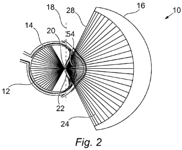
Figure 2 is a schematic top view of the apparatus of figure 1 which details
the light rays entering the eye;
Figure 3 is a schematic top view of a first embodiment of the imaging
device of the imaging apparatus of figure 1;
Figure 4 is a side view of figure 3;
Figure 5 is a schematic illustration of the unfolded light beam path of figure
3;
Figure 6 is a more detailed illustration of figure 5;
Figure 7 is a schematic top view of a second embodiment of the imaging
device of the imaging apparatus of figure 1;
Figure 8 is a side view of figure 7; and
CA 02802786 2012-12-14
WO 2012/001381 PCT/GB2011/051037
24
Figure 9 a schematic illustration of the operation of the apparatus of the
present invention when imaging two eyes.
Figures 1 and 2 illustrate an apparatus 10 for illuminating, imaging and
treating the retina 12 of an eye 14. The apparatus 10 includes an imaging
device 16 which is capable of obtaining a substantially one-dimensional
image of the retina 12. That is, the imaging device 16 is capable of
obtaining a line image of the retina 12.
The apparatus 10 also includes a support structure (not shown) for
supporting the imaging device 16. The imaging device 16 is pivotably
mounted to the support structure. The support structure may include a
base member which may be mounted to a desk, or the like. Alternatively,
the support structure may include headgear, which may, for example, be
worn by a patient.
In the embodiment described here the apparatus 10 includes an imaging
device 16 which is capable of obtaining a substantially one-dimensional
image of the retina 12. However, it should be appreciated that the
apparatus 10 may alternatively include an illuminating device, which,
instead of obtaining an image of the retina, simply illuminates the retina
with collimated light. The illuminating device may include a planar light
source and is capable of producing light in a plane, such that the
illuminating device is capable of illuminating a circumferential line on the
retina.
As illustrated in figure 1, the imaging device 16 is rotatable about the eye
14. As illustrated in figure 2, the imaging device 16 is rotatable about an
axis 18. The axis 18 is located in the region of the pupillary point 20 of the
eye 14. The axis 18 may be coincident with the front nodal point 22 of the
CA 02802786 2012-12-14
WO 2012/001381 PCT/GB2011/051037
eye 14. The axis 18 is parallel to the direction of the substantially one-
dimensional image of the retina 12 (see figure 2). The axis 18 lies on a
plane of light 24 produced by the imaging device 16. Figure 2 illustrates
the rays of light 28 generated by the imaging device 16 to image the retina
5 12. It should be noted that the refraction of the light rays 28 by the lens
of
the eye 14 have been omitted for clarity.
As the imaging device 16 is rotated about the axis 18, a plurality of one-
dimensional images of the retina 12 are obtained. These images are then
10 combined to form a two-dimensional image of the retina 12. The
apparatus 10 includes one or more data processing devices (not shown)
which are used to store the plurality of one-dimensional images and/or
combine them to form the two-dimensional image.
15 The imaging device 16 is rotated through the axis 18 at a fast enough rate
to avoid large eye motion. Typically, a full rotation takes around 100 ms to
200 ms. However, it should be appreciated that slower or faster scanning
rates may be used.
20 Figures 3 and 4 are schematic illustrations of a first embodiment of the
imaging device 16. The imaging device 16 in this embodiment is
configured to obtain a one-dimensional image of the retina 12 by scanning
collimated light 30 across the retina 12 of the eye 14. That is, the imaging
device 16 is therefore capable of performing a one-dimensional scan 32 of
25 collimated light 30 across the retina 12 of the eye 14.
In this embodiment, the rotational axis 18 of the imaging device 16 is
parallel to a plane 34 produced by the one-dimensional collimated light
scan 32 produced by the imaging device 16. That is, the rotational axis 18
of the imaging device 16 lies on the plane 34 defined by the one-
CA 02802786 2012-12-14
WO 2012/001381 PCT/GB2011/051037
26
dimensional collimated light scan 32 produced by the imaging device 16,
and the plane of the rotational axis 18 of the imaging device 16 is
orthogonal to the plane 34 defined by the one-dimensional collimated light
scan 32 produced by the imaging device 16.
With reference to figure 3 in particular, the imaging device 16 comprises a
source of collimated light 36, a scanning element 38 and a scan transfer
device 40.
The source of collimated light 36 transmits light 30 to the scanning
element 38 via a focussing lens 44 (see below). The focussing lens 44
provides collimated light to the eye 14 via the scan transfer device 40 (see
below). In the embodiment described here, the scanning element 38 is a
one-dimensional microelectromechanical system (MEMS) scanner.
However, it should be appreciated that alternative scanning elements
could also be used. The scanning element 38 scans the collimated light
30 across the scan transfer device 40. The source of collimated light 36
and the scanning element 38 combine to produce the one-dimensional
collimated light scan 32 from a point 46.
The scan transfer device 40, which, in the embodiment described and
illustrated here is an ellipsoidal mirror, has two foci; a first focal point
48
and a second focal point 50. The point 46, from which the one-
dimensional collimated light scan 32 emanates, is located at the first focal
point 48 of the scan transfer device 40 and the pupillary point 20 of the
eye 14 is located at the second focal point 50 of the scan transfer device
40. Since the scan transfer device 40 has two focal points 48, 50, the
scan transfer device 40 transfers the one-dimensional collimated light
scan 32 from the point 46 into the eye 14. Thus, the imaging device 16
CA 02802786 2012-12-14
WO 2012/001381 PCT/GB2011/051037
27
obtains a one-dimensional image of the retina 12 by scanning the
collimated light 30 across the retina 12 of the eye 14.
The distance between the two foci 48, 50 of the scan transfer device 40 is
approximately 40 mm to 150 mm. It is preferable that the distance
between the two foci 48, 50 of the scan transfer device 40 is 50 mm to 60
mm. This arrangement reduces the degree of variable magnification and
focal offset during scanning.
The rotational axis 18 of the imaging device 16 also lies on the second
focal point 50 of the scan transfer device 40. That is, in the embodiment
illustrated and described here, the rotational axis 18 of the imaging device
16 is located at the pupillary point 20 of the eye 14 and the second focal
point 50 of the scan transfer device 40.
As described above, and with reference to figure 4, as the imaging device
16 is rotated about the axis 18 a plurality of one-dimensional images of the
retina 12 are obtained. These images are then combined to form a two-
dimensional image of the retina 12.
The source of collimated light 36 in the embodiment described and
illustrated here is a laser. The laser 36 is coupled into a first optical
fibre
42, which is a single mode polarisation maintaining fibre. The laser 36 may
be located in a housing 19 (see figure 1) which is remote from the imaging
device 16 and the first optical fibre 42 transfers the collimated light 30
from
the laser 36 to the imaging device 16. In this arrangement the imaging
device 16 is moveable with respect to the housing 19. Alternatively, the
laser 36 may be located with the imaging device 16 and the laser 36 and
first optical fibre 42 rotate with the imaging device 16.
CA 02802786 2012-12-14
WO 2012/001381 PCT/GB2011/051037
28
The imaging device 16 also includes a protective window 17, which
protects the eye 14 from dust and debris. The protective window 17 may
be mounted around the eye 14 so that its position is fixed relative to the
eye 14, or the protective window 17 may be mounted with the imaging
device 16 so that it rotates with the imaging device 16.
With reference to figure 5, the diverging light emitted by the first optical
fibre 42 is refocused to the retina 12 of the eye 14 through the combination
of a focussing lens 44, the scan transfer device 40 and the lens 54 of the
eye 14. As illustrated in figure 5, the retinal planes are labelled (R) and
the pupil planes are labelled (P).
With reference to figure 6, reflected light from the retina 12 is refocused to
a second optical fibre 56 through the combination the lens 54 of the eye
14, the scan transfer device 40 and the focussing lens 44. The second
optical fibre 56 is a multi-mode optical fibre with a large diameter core.
As illustrated in figure 6, a beam splitter 58 is positioned between the first
and second optical fibres 42, 56. The beam splitter 58 is a plate glass
beam splitter and is oriented at 45 degrees to the focussing lens 44. The
beam splitter 58 reflects a portion of the collimated light 30 emitted from
the first optical fibre 42 to the focussing lens 44 and into the eye 14. The
beam splitter 58 may be uncoated and provides approximately 90/10
splitting ratio by utilising polarisation specific Fresnel reflections. The
use
of single mode polarisation maintaining optical fibres allows a stable
optical power to be achieved during scanning. Approximately 90% of the
light from the first optical fibre 42 is transmitted through the beam splitter
58, with the remaining 10% going to the eye 14. The light transmitted
through the beam splitter 58 on input may be used to monitor the power of
the collimated light 30 for safety reasons.
CA 02802786 2012-12-14
WO 2012/001381 PCT/GB2011/051037
29
The majority of the reflected light from the retina 12 is transmitted through
the beam splitter 58 and focussed to the second optical fibre 56. The
second optical fibre 56 is connected to at least one fast single point photo-
detector element 60, such as an avalanche photo detector APD photo-
detector, PIN diode, photomultiplier tube (PMT), silicon photo multiplier
(SPM), or similar single point detectors. The detector 60 may be located
in the housing 19 which is remote from the imaging device 16 and the
second optical fibre 56 transfers the reflected collimated light 30 from the
imaging device 16 to the detector 60. In this arrangement the imaging
device 16 is moveable with respect to the housing 19. Alternatively, the
detector 60 may be located with the imaging device 16 and the detector 60
and second optical fibre 56 rotate with the imaging device 16.
The apparatus 10 also includes at least one data processing device (not
shown), such as a computer, for storing the plurality of at least one-
dimensional images and combining the images to obtain the two-
dimensional image. The data processing device is located remotely from
the imaging device 16 and may be located within the housing 19.
If the laser 36 and detector 60 are located with the imaging device 16, the
apparatus 10 may further comprise one or more data communication
devices, such as optical fibres etc., to allow the data processing device to
communicate with, and/or control, the laser 36 and detector 60. The
communication between the imaging device 16 and the data processing
device may be wireless.
The apparatus 10 may also be capable of performing multiple wavelength
imaging. Multiple wavelength imaging may be achieved, for example, by
CA 02802786 2012-12-14
WO 2012/001381 PCT/GB2011/051037
providing multiple lasers combined into one optical fibre, which is time-
multiplexed and synchronised with a single detector.
Alternatively, two single mode optical fibres could transmit the collimated
5 light from two different sources of collimated light into the beam path. In
this arrangement, the lasers would again be time-multiplexed with a single
detector. In order to avoid time-multiplexing, a further beam splitter with
wavelength splitting properties may be inserted between the beam splitter
58 and the second optical fibre 56, such that the second optical fibre 56
10 transmits light of different wavelength bands to two single point photo
detectors.
Figures 7 and 8 are schematic illustrations of a second embodiment of the
imaging device 116 of the apparatus 10. The imaging device 116 in this
15 embodiment is configured to obtain a substantially one-dimensional image
of the retina 12 by manipulating light from a source of light 136 to produce
a plurality of light beams 130 which illuminate the retina 12 of the eye 14.
The plurality of light beams 130 form a plane of light 134 which illuminates
the retina 12. The imaging device 116 may manipulate light from the
20 source of light 136 by passing the light through a line generating element
138, such as a cylindrical lens, toroidal lens or gradient refractive index
lens. That is, the imaging device 116 is therefore capable of manipulating
the source of light 136 by passing the light through a line generating
element, or the like, to produce a plurality of light beams 130 which
25 illuminate the retina 12 of the eye 14.
The source of light 136 may include, a diverging laser diode and a toroidal
lens, a lamp source with a slit aperture, a light emitting diode (LED), a
Vertical Cavity Surface Emitting Laser (VCSEL), a super luminescent
30 diode, a diode laser or a collimated incandescent lamp.
CA 02802786 2012-12-14
WO 2012/001381 PCT/GB2011/051037
31
The light beam produced by the source of light 136 may be collimated.
That is, the apparatus may use a collimated light source to illuminate the
retina 12 of the eye 14.
In this embodiment, the rotational axis 118 of the imaging device 116 is
parallel to the plane 134 produced by the imaging device 116. That is, the
rotational axis 118 of the imaging device 116 lies on the plane 134 defined
by the plurality of light beams 130 produced by the imaging device 116,
and the plane of the rotational axis 118 of the imaging device 116 is
orthogonal to the plane 134 defined by the plurality of light beams 130
produced by the imaging device 116.
With reference to figures 7 and 8, the arrangement of the second
embodiment of the imaging device 116 is similar to the arrangement of the
first embodiment (figures 3 and 4). The imaging device 116 comprises a
source of light 136, a light manipulating element 138 and a scan transfer
device 140.
In the embodiment described here the source of light 136 is a laser.
However, it should be appreciated that the source of light does not
necessarily have to be collimated.
The source of collimated light 136 transmits collimated light 130 to the light
manipulating element 138. The source of collimated light 136 and the light
manipulating element 138 combine to produce a plurality of light beams
130 from a point 146.
The scan transfer device 140 is identical to that described in relation to the
first embodiment of the imaging device 16. The point 146 from which the
CA 02802786 2012-12-14
WO 2012/001381 PCT/GB2011/051037
32
plurality of light beams 130 emanate is located at the first focal point 148
of the scan transfer device 140 and the pupillary point 20 of the eye 14 is
located at the second focal point 150 of the scan transfer device 140.
Again, since the scan transfer device 140 has two focal points 148, 150,
the scan transfer device 140 transfers the plurality of light beams 130 from
the point 146 into the eye 14. Thus, the imaging device 116 obtains a
one-dimensional image of the retina 12 by illuminating the retina 12 of the
eye 14 with a plane of light 134 and detecting the reflected light therefrom.
The rotational axis 118 of the imaging device 116 again lies on the second
focal point 150 of the scan transfer device 140. That is, in the
embodiment illustrated and described here, the rotational axis 118 of the
imaging device 116 is located at the pupillary point 20 of the eye 14 and
the second focal point 150 of the scan transfer device 140.
The apparatus 100 also includes a support structure (not shown) for
supporting the imaging device 116. The imaging device 116 is pivotably
mounted to the support structure. The support structure may include a
base member which may be mounted to a desk, or the like. Alternatively,
the support structure may include headgear, which may, for example, be
worn by a patient.
Again as described above, as the imaging device 116 is rotated about the
axis 118 a plurality of one-dimensional images of the retina 12 are
obtained. These images are then combined to form a two-dimensional
image of the retina 12.
The laser 136 is coupled into the first optical fibre, which is a single mode
polarisation maintaining fibre. The laser 136 may be located in the housing
19 which is remote from the imaging device 116 and the first optical fibre
CA 02802786 2012-12-14
WO 2012/001381 PCT/GB2011/051037
33
transfers the collimated light 130 from the laser 136 to the imaging device
116. In this arrangement the imaging device 116 is again moveable with
respect to the housing 19. Alternatively, the laser 136 may be located with
the imaging device 116 and the laser 136 and first optical fibre rotate with
the imaging device 116.
With reference to figure 7, the collimated light 130 illuminates the retina 12
of the eye 14 through the combination of the light manipulating element
138, the scan transfer device 140 and lens of the eye 14.
A beam splitter 158 is positioned between the light manipulating element
138 and the scan transfer device 140. Reflected light from the retina 12 is
refocused to a detector 160 through the combination of the lens 54 of the
eye 14, the scan transfer device 140 and a focussing lens 152. The
detector 160 is a linear array of photo detection elements, such as a CCD
or CMOS device. The detector 160 in this embodiment should be a line
array. However, it should be appreciated that the line array could be one-
dimensional or two-dimensional.
The beam splitter 158 is a plate glass beam splitter and is oriented at 45
degrees to the focussing lens 152. It should be appreciated that the beam
splitter 158 does not necessarily need to be oriented at 45 degrees and
other angles of orientation are possible with the same effect.
Approximately 90% of the light from the scan transfer device 140 is
transmitted through the beam splitter 158 and focussed by the focussing
lens 152 to the detector 160.
The detector 160 may be located in the housing 19 which is remote from
the imaging device 116 and a second optical fibre (not shown) may
transfer the reflected collimated light 130 from the imaging device 116 to
CA 02802786 2012-12-14
WO 2012/001381 PCT/GB2011/051037
34
the detector 160. In this arrangement the imaging device 116 is moveable
with respect to the housing 19. Alternatively, the detector 160 may be
located with the imaging device 116 and the detector 160 rotates with the
imaging device 116.
If the laser 136 and detector 160 are located with the imaging device 116,
the apparatus 10 may further comprise one or more data communication
devices, such as optical fibres etc., to allow the data processing device to
communicate with, and/or control, the laser 136 and detector 160.
The imaging device 116 also includes a protective window 117, which
protects the eye 14 from dust and debris. The protective window 117 may
be mounted around the eye 14 so that its position is fixed relative to the
eye 14, or the protective window 117 may be mounted with the imaging
device 16 so that it rotates with the imaging device 116.
Multiple wavelength imaging may again be achieved by providing multiple
lasers with different wavelengths. Again, a beam splitter with wavelength
splitting properties may be inserted between the scan transfer device 140
and the one or more detectors 160. In this arrangement detector 160 may
be provided with a Bayer filter to facilitate multiple wavelength detection.
With reference to figure 9, the imaging device 16, 116 may be pivotable
about an axis 62. The axis 62 is orthogonal to the rotational axis 18, 118
of the imaging device 16, 116. The imaging device is therefore pivotable
between a first position (left side of figure 9), in which the imaging device
16, 116 may be used to obtain a two-dimensional image of the first retina
12a of a first eye 14a, and a second position (right side of figure 9), in
which the imaging device 16, 116 may be used to obtain a two-
CA 02802786 2012-12-14
WO 2012/001381 PCT/GB2011/051037
dimensional image of the first retina 12b of a second eye 14b. The
apparatus 10 can therefore image both eyes of a patient.
The imaging device 16, 116 may be configured such that is rotation about
5 the axis 18, 118 may be controlled by a computer, or the like. This allows
the imaging process to be automated, which increases the speed in which
the two-dimensional image is created. This also improves the repeatability
of the image acquisition.
10 The imaging device may be configured such that its rotation about the axis
is automated. The rotation of the imaging device may be computer-
controlled.
The apparatus 10 of the present invention can be manufactured at a lower
15 cost than known retinal imaging apparatus, such as scanning laser
ophthalmoscopes (SLOB), as the apparatus 10 does not require
conventional laser scanning elements, such as polygon mirrors. The
apparatus 10 can be made more compact than known retinal imaging
apparatuses, since the apparatus uses a smaller number of components
20 than known retinal imaging apparatuses. The apparatus 10 of the present
invention also includes a smaller number of optical surfaces, which
increases the optical efficiency of the apparatus. The result of this is that,
for the same amount of input power to the eye, the total power at the
imaging detector is higher than known methods. Also, because the
25 rotation of the entire imaging device 16, 116 is about the pupillary point
of
the eye, only a single, small sized, scan transfer device is required. This
reduces the cost and size of the apparatus. Also, the apparatus 10 may
be capable of performing "wide field" imaging or "narrow field" imaging.
Therefore, the apparatus is scalable for different markets. Furthermore,
30 depending on the geometry of the scan transfer device, no focal correction
CA 02802786 2012-12-14
WO 2012/001381 PCT/GB2011/051037
36
is necessary to achieve high resolution imaging. This yields higher
resolution images than known methods. Also, the apparatus 10 supports
loose confocal imaging to avoid back reflections from a window, cornea
and other surfaces. This means that for point scans or line scans an
aperture can be used to block reflections from the cornea that would
otherwise cause lack of contrast and artefacts in the image.
Modifications and improvements may be made to the above without
departing from the scope of the present invention. For example, although
the rotational axis 18 of the imaging device 16 has been illustrated and
described above as being coincident with the pupillary point 20 of the eye
14, it should be appreciated that the axis 18 could be located generally
around the front nodal point 22 of the eye 14. That is, the axis 18 could be
located on the optical axis 26 in front of the lens, in the plane of the iris,
or
at the rear nodal point of the eye 14. In order to achieve the widest field of
view, i.e. to avoid clipping of the light beam, the axis 18 should be located
at the front of the lens of the eye 14, i.e. in the plane of the iris. The
rotational axis 18 of the imaging device 16 is therefore within +/- 4mm of
the plane of the iris.
Furthermore, although the rotational axis 18 of the imaging device 16 has
been illustrated and described above as lying on the horizontal plane 24
defined by the optical axis 26 of the eye 14, it should be appreciated that
the rotational axis 18 of the imaging device 16 may be perpendicular to the
horizontal plane 24. Alternatively, the rotational axis 18 of the imaging
device 16 may be neither parallel nor perpendicular to the horizontal plane
24. In any of these arrangements the axis of rotation 18 of the imaging
device 16 should remain parallel to the direction of the one-dimensional
image.
CA 02802786 2012-12-14
WO 2012/001381 PCT/GB2011/051037
37
Also, although the pupillary point 20 of the eye 14 has been described
above as being located at the second focal point 50 of the scan transfer
device 40, it should be appreciated that the pupillary point 20 of the eye 14
includes any point in the region of the pupillary point 20 on the optical axis
26 in front of the lens, in the plane of the iris, the front nodal point of
the
eye 14, or the rear nodal point of the eye 14. Therefore, any point in the
region of the pupillary point 20, which includes the region in front of the
lens, in the plane of the iris, the front nodal point of the eye 14, or the
rear
nodal point of the eye 14, could be located at the second focal point 50 of
the scan transfer device 40.
Furthermore, although the source of collimated light 36 has been
described above as a laser, it should be appreciated that the source of
collimated light 36 may alternatively be a light emitting diode (LED), a
Vertical Cavity Surface Emitting Laser (VCSEL), a super luminescent
diode, a diode laser or a collimated incandescent lamp.
Also, although the beam splitter 58 has been described above as
providing 90/10 splitting ratio, it should be appreciated that beam splitters
with other splitting ratios may be used, such as 80/20, 50/50, or other
types of beam splitters, such as aperture beam splitters, polarisation beam
splitters, dichroic mirrors (for fluorescence imaging) where the input beam
diameter is smaller than the output beam diameter. Also, the beam splitter
158 may again be oriented at other suitable angles than 45 degrees with
the same effect.
Furthermore, although the scanning element has been illustrated and
described above as being a MEMS scanner, it should be appreciated that
the scanning element could be any oscillating mechanism suitable for
scanning the collimated light 30 across the scan transfer device 40. This
CA 02802786 2012-12-14
WO 2012/001381 PCT/GB2011/051037
38
may include resonant scanners, oscillating plane mirrors and the like. The
scanning element should preferably be capable of operating at high speed
(i.e. above 5 kHz) and provide a high amplitude of scan (i.e. up to 180
degrees).
Also, although the scan transfer device 40 has been illustrated and
described above as an ellipsoidal mirror, it should be appreciated that the
scan transfer device 40 may alternatively be a tilted spherical mirror, an
aspherical mirror, an elliptical mirror, an ellipsoidal mirror, a pair of
parabola mirrors, a pair of paraboloidal mirrors or a lens system.
Furthermore, although the imaging device 16, 116 has been described
above as being capable of obtaining a one-dimensional image of the retina
12, i.e. a line image of the retina 12, and that a two-dimensional image of
the retina is obtained by combining a number of these images together, it
should be appreciated that the imaging device may be capable of
obtaining a two-dimensional image of the retina. Therefore, in use, the
imaging device may be rotated about the axis to obtain a plurality of two-
dimensional images of the retina. The plurality of two-dimensional images
may be combined to obtain a larger two-dimensional image of the retina.
That is, the plurality of two-dimensional images may produce a montage
two-dimensional image of the retina. In this arrangement, the plurality of
two-dimensional images may be "stitched" to form a larger two-
dimensional image of the retina. Alternatively, the plurality of two-
dimensional images may be arranged to overlap in the direction of rotation
of the imaging device. The plurality of overlapping two-dimensional
images of the retina may be "stitched" to form the montage two-
dimensional image of the retina. In this arrangement a two-dimensional
scanning element may be used to obtain the plurality of two-dimensional
images of the retina. The scanning element is capable of scanning in two
CA 02802786 2012-12-14
WO 2012/001381 PCT/GB2011/051037
39
directions. At least one of the scan directions should be in the same
direction as the axis of rotation of the imaging device. The two-
dimensional images may have a rectangular aspect ratio, such as
1000:100. However, it should be appreciated that the aspect ratio could
be any desired value. The two-dimensional images are acquired at a fast
frame rate, such as 30 frames per second, to avoid eye motion. The
imaging device in this arrangement may be rotated at a slower rate than
the arrangement described above. The two-dimensional images are then
combined to form a larger two-dimensional image, such as an image with
an aspect ratio of 1000:800 or 1000:1000. The scanning element may be
a two-dimensional MEMS scanner. In this arrangement, the two-
dimensional images may be captured using a two-dimensional rectangular
array, as described above.
Also, although the apparatus 10 has been illustrated and described above
as comprising a single imaging device 16, 116, it should be appreciated
that the apparatus 10 may comprise two imaging devices 16. 116, wherein
each imaging device 16, 116 may be capable of obtaining at least a one-
dimensional image of the retina and may be rotatable about an axis which
is parallel to the direction of the at least one-dimensional image. In this
arrangement the imaging devices 16, 116 may be rotated together or
separately. The imaging devices 16, 116 may be located in a single
housing, or located separately in two separate housings. This
arrangement allows two eyes to be imaged at the same time.
Furthermore, it should be appreciated that the apparatus 10, 100 may also
be used for fluorescence imaging by imaging at one wavelength and
detecting at another, as is common in applications such as angiography
and auotofluorescence imaging. It should therefore be appreciated that
the apparatus 10, 100 may obtain an image of the retina by receiving light
CA 02802786 2012-12-14
WO 2012/001381 PCT/GB2011/051037
reflected from the retina or fluorescent light emitted by the retina on
excitation thereof.
Also, although the apparatus 10, 100 has been described above as for
5 illuminating and imaging the retina 12 of the eye 14, it should be
appreciated that the apparatus 10, 100 may also be used to administer
treatment to the retina 12 by illuminating the retina 12 with collimated light
of a suitable wavelength and/or power. Treating the retina 12 may include
the following steps: (i) identifying a region of the retina for treatment,
(ii)
10 specifying the size of the treatment area through treatment planning,
linked to an imaging system and (iii) guiding the treatment either through
manual control or pre-specified automated control to deliver the treatment
illumination to single or multiple sites via a common input path to the
imaging source(s). This provides a correlation between the treatment
15 geography and treatment planning derived from the imaging system.
Treating the retina 12 may also include the optional steps of viewing an
image of the retina 12 during the treatment and/or re-imaging the retina to
confirm the treatment is successful.
20 That is, the present invention also provides an apparatus for illuminating
the retina with collimated light for use in treating the retina. The present
invention also provides a method for illuminating the retina with collimated
light for use in treating the retina.