Note: Descriptions are shown in the official language in which they were submitted.
CA 02803071 2014-12-15
1
WIRE BRUSH
I. Back2round
A. Field of Invention
[0001] The present invention relates generally to wire brushes, and
more specifically
to wire brushes providing an improved handle.
B. Description of the Related Art
100021 Numerous types and styles of wire brushes are known. While many
known
wire brushes generally work well for their intended purposes, what is needed
is a wire brush that
provides better performance than known wire brushes.
II. Summary
[0002a] Certain exemplary embodiments provide a wire brush comprising:
a brush
body having a proximal end and a distal end, the brush body comprising: a head
on the distal end of
the brush body; a handle on the proximal end of the brush body; and, only one
finger separator: that
is suitable to separate two fingers from an associated typical person's hand;
and, that extends at least
0.25 inches downwardly from a bottom surface of the handle; wherein a
plurality of wire type tufts
extend downwardly from a bottom surface of the head; wherein the handle
comprises a first finger
receiving area on the bottom surface of the proximal side of the finger
separator that is suitable to
receive at least four fingers from the associated typical person's hand;
wherein the handle comprises
a second finger receiving area on the bottom surface of the distal side of the
finger separator that is
suitable to receive at least two fingers from the associated typical person's
hand; and wherein the
head has first and second sides, a bottom surface, and a frictional grip
surface wholly encompassed
on the first side of the head.
CA 02803071 2014-12-15
la
[0002b] Other exemplary embodiments provide a wire brush comprising: a
brush
body having a proximal end and a distal end, the brush body comprising: a head
having first and
second sides on the distal end of the brush body; a handle on the proximal end
of the brush body;
and, only one finger separator: that is suitable to separate two fingers from
an associated typical
person's hand; and, that extends at least 0.25 inches downwardly from a bottom
surface of the
handle; a frictional grip surface on the first side of the head; a frictional
grip surface on the second
side of the head; a frictional grip surface on a top surface of the brush
body; a plurality of wire
type tufts extending downwardly from a bottom surface of the head; a scraper
comprising a
scraper body and a scraper blade; wherein the scraper blade is suitable to
scrape material from an
associated surface; wherein the handle comprises a first finger receiving area
on the bottom
surface of the proximal side of the finger separator that is suitable to
receive at least four fingers
from the associated typical person's hand and a frictional grip surface on the
first finger receiving
area; wherein the handle comprises a second finger receiving area on the
bottom surface of the
distal side of the finger separator that is suitable to receive at least one
finger from the associated
typical person's hand; and wherein the frictional grip surfaces on the first
and second sides of the
head do not extend onto the bottom surface of the head and are each suitable
to receive four
fingers from the associated typical person's hand.
[0003] According to one embodiment of this invention, a wire brush may
comprise:
a brush body having a proximal end and a distal end, the brush body
comprising: a head on the
distal end of the brush body; a handle on the proximal end of the brush body;
and, only one
finger separator: that is suitable to separate two fingers from an associated
typical person's hand;
and, that extends at least 0.25 inches downwardly from a bottom surface of the
handle. A
plurality of wire type tufts may extend downwardly from a bottom surface of
the head. The
handle may comprise a first finger receiving area on the bottom surface of the
proximal side of
the finger separator that is suitable to receive at least four fingers from
the associated typical
CA 02803071 2013-02-15
2
person's hand and a second finger receiving area on the bottom surface of the
distal side of the
finger separator that is suitable to receive at least one finger from the
associated typical person's
hand. The wire brush may have a scraper comprising a scraper body and a
scraper blade where
the scraper blade is suitable to scrape material from an associated surface. A
mechanical fastener
may be manually adjustable between: (1) an attached condition where the
mechanical fastener
attaches the scraper body to the brush body; and, (2) a detached condition
where the mechanical
fastener does not attach the scraper body to the brush body. One of the brush
body and the
scraper body has first and second tabs and the other of brush body and the
scraper body has first
and second grooves that receive the first and second tabs when the mechanical
fastener is in the
attached condition.
[0004] According to another embodiment of this invention, a wire brush
may
comprise: a brush body having a proximal end and a distal end, the brush body
comprising: a
head on the distal end of the brush body; a handle on the proximal end of the
brush body; and,
only one finger separator: that is suitable to separate two fingers from an
associated typical
person's hand; and, that extends at least 0.25 inches downwardly from a bottom
surface of the
handle. A plurality of wire type tufts may extend downwardly from a bottom
surface of the
head. The handle may comprise a first finger receiving area on the bottom
surface of the
proximal side of the finger separator that is suitable to receive at least
four fingers from the
associated typical person's hand; and, a second finger receiving area on the
bottom surface of the
distal side of the finger separator that is suitable to receive at least one
finger from the associated
typical person's hand.
[0005] According to yet another embodiment of this invention, a wire
brush may
comprise: a brush body comprising a head from which a plurality o f wire type
tufts extend; a
scraper comprising a scraper body and a scraper blade; wherein the scraper
blade is suitable to
scrape material from an associated surface; and, a mechanical fastener that is
manually
adjustable between: (1) an attached condition where the mechanical fastener
attaches the scraper
body to the brush body; and, (2) a detached condition where the mechanical
fastener does not
CA 02803071 2013-02-15
3
attach the scraper body to the brush body. One of the brush body and the
scraper body has first
and second tabs and the other of brush body and the scraper body has first and
second grooves
that receive the first and second tabs when the mechanical fastener is in the
attached condition.
[0006] Numerous benefits and advantages of the invention will become
apparent to
those skilled in the art to which it pertains upon a reading and understanding
of the following
detailed specification.
III. Brief Description of the Drawings
[0007] The invention may take physical form in certain parts and
arrangement of
parts, embodiments of which will be described in detail in this specification
and illustrated in the
accompanying drawings which form a part hereof and wherein:
[00081 FIGURE 1 is a perspective view of a wire brush according to one
embodiment
of this invention.
100091 FIGURE 2 is a side view of the wire brush shown in FIGURE 1.
[0010] FIGURE 3 is a top view of the wire brush shown in FIGURE 1.
[0011] FIGURE 4 is an assembly view of the wire brush shown in FIGURE i.
[0012] FIGURES 5 is a sectional view through line 5-5 in FIGURE 6.
[0013] FIGURE 6 is a top view of a wire brush according to another
embodiment of
this invention.
[0014] FIGURE 1 is a side view of the wire brush shown in FIGURE 6.
CA 02803071 2013-02-15
4
[0015] FIGURE 8 is a bottom view of the wire brush shown in FIGURE 6.
[0015] FIGURE 9 is a perspective view of the wire brush shown in FIGURE
6.
[0016] FIGURE 10 is an assembly view of the wire brush shown in FIGURE
6.
[0017] FIGURE 11 is a section view through line 11-1 1 in FIGURE 12.
[00181 FIGURE 12 is a top view of wire brush according to yet another
embodiment
of this invention.
[0019] FIGURE 13 is a side view of the wire brush shown in FIGURE 12.
[0020] FIGURE 14 is a bottom view of the wire brush shown in FIGURE 12.
[0021] FIGURE 15 is a perspective view of the wire brush shown in FIGURE
12.
[0022] FIGURE 16 is an assembly view of the wire brush shown in FIGURE
12.
100231 FIGURE 17 is a perspective view of still another embodiment of
this
invention.
[0024] FIGURE 18 is an assembly view of the wire brush shown in FIGURE
17.
IV. Detailed Description of the Invention
[0025] Referring now to the drawings wherein the showings are for
purposes of
illustrating embodiments of the invention only and not for purposes of
limiting the same, and
wherein like reference numerals are understood to refer to like components,
FIGURES 1-4 show
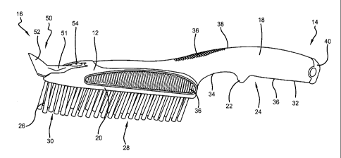
CA 02803071 2013-02-15
a wire brush 10 having a brush body 12. For reference purposes only, the term
"proximal" will
be used to refer to one end of the brush 10 and the term "distal" will be used
to refer to the
opposite end. For the embodiments shown in FIGURES 1-16, the proximal end 14
is the end
having a handle 18 and the distal end 16 is the end having a head 20, but this
reference structure
is not a requirement for this invention. A plurality of wire type tufts 26 may
extend downwardly
from a bottom surface 28 of the head 20. A tuft 26 can include one or more
filaments or bristles
30. The specific number of filaments or bristles used to make up one tuft 26
can be any number
chosen by a person of ordinary skill in the art. By "wire type" tufts it is
meant that the materials
used to make the bristles 30 forming the tufts 26 are relatively stiff and
thus useful for non-
limiting purposes such as removing paint from a surface. The material used to
make the bristles
30 may, in one embodiment, include a metal. In one specific embodiment, all
the tufts 26 are
formed exclusively of steel bristles 30, which may be stainless steel, high
carbon steel,
galvanized steel or the like. In other embodiments, tufts 26 may be formed of
aluminum, brass,
bronze, or other alloys. In still other embodiments, tufts 26 may be formed of
synthetic or
natural fibers, including nylon, abrasive nylon, conductive nylon, polyester,
polypropylene,
polyethylene, horsehair and tampico fiber. As the use of a wire brush is well
known to persons
of skill in the art, details will not be provided here.
[0026] A finger separator 22 may extend downwardly from a bottom surface
24 of
the handle 18, as shown. By "finger separator" it is meant a component that is
suitable and
indented to physically separate two neighboring fingers on a person's hand.
The finger separator
22 can be of any size and shape chosen with the sound judgment of a person of
skill in the art. In
one embodiment, the finger separator 22 may extend at least 0.25 inches from
the bottom surface
24 of the handle 18. In another embodiment, the finger separator 22 may extend
at least 0.375
inches from the bottom surface 24 of the handle 18. In one embodiment, shown,
only one finger
separator 22 is used with the wire brush 10. This improves the options for
using the handle 18 as
will be discussed further below. The handle 18 may have first and second
finger receiving areas
32, 34 on the bottom surface 24 of the handle 18. The first finger receiving
area 32 is on the
proximal side of the finger separator 22 and is suitable to receive at least
four fingers from a
CA 02803071 2013-02-15
6
typical person's hand. In one non-limiting embodiment, the first finger
receiving area 32 is
approximately 3.5 inches long. The second finger receiving area 34 is on the
distal side of the
finger separator 22 and is suitable in one embodiment to receive one finger
from a typical
person's hand. In another embodiment, the second finger receiving area 34 is
suitable to receive
two fingers from a typical person's hand. In yet another embodiment, the
second finger
receiving area 34 is suitable to receive three fingers from a typical person's
hand.
[0027] With continuing reference to FIGURES 1-4, the wire brush 10 may
have one
or more frictional grip surfaces 36 to facilitate gripping the wire brush 10
when the wire brush 10
is applied to a surface. The number, style, size, and location of frictional
grip surfaces positioned
on the wire brush 10 can be any chosen with the sound judgment of a person of
skill in the art.
For the embodiment shown, the frictional grip surfaces 36 are formed of
multiple ribs that extend
from the surface of the wire brush 10. In one embodiment, there may be a
frictional grip surface
36 located on either side or both sides of the head 20. In one embodiment,
either or both of the
frictional grip surfaces 36 on the head 20 are suitable to receive four
fingers from a typical
person's hand. In one non-limiting embodiment, each frictional grip surfaces
36 located on the
side of the head 20 is approximately 4.5 inches long. In another embodiment,
there may be a
frictional grip surface 36 located on the first finger receiving area 32. In
one specific
embodiment, the frictional grip surface 36 located on the first finger
receiving area 32 is suitable
to receive four fingers from a typical person's hand. In yet another
embodiment, there may be a
frictional grip surface 36 located on a top surface 38 of the brush body 12.
For the embodiment
shown, the frictional grip surface 36 located on the top surface 38 extends
from above the
proximal end of the head 20 to above the distal end of the handle 18.
[0028] In one embodiment a hammer surface 40 may be positioned on the
wire brush
and used to forcefully strike a surface as is well known to those of skill in
the art. For the
embodiment shown, the hammer surface 40 is positioned on the proximal end of
the handle 14.
The hammer surface 40 can be formed of any material and may be of any style
and size chosen
CA 02803071 2013-02-15
7
with the sound judgment of a person of skill in the art. For the embodiment
shown, the hammer
surface 40 is a metal cap held to the proximal end of the handle 18 with a
swage collar 42.
[00291 The brush body 12 may be formed of any material and in any manner
chosen
with the sound judgment of a person of skill in the art. In one embodiment,
the brush body 12
includes an inner structure 44 formed of polypropylene and an overmold 46
formed of a
santoprene rubber.
[0030] With reference now to FIGURES 1-16, it should be noted that the
wire brush
described is well suited to provide at least four different use options. A
first use option is a
one hand option where the user grips the proximal end of the handle 18 with
one hand and places
all four fingers of the hand (it being understood that the user's thumb would
be placed on the
side or top of the handle 20) in the first finger receiving area 32. The
finger separator 22 may be
used to limit the relative motion of the hand with respect to the wire brush
10 in the distal
direction (the person's index finger may abut the proximal side of the finger
separator 22). A
second use option is a one hand option where the user grips the handle 18 with
one hand and
places at least one finger (at least the index finger) in the second finger
receiving area 34 while
the remaining fingers of the hand (it being understood that the user's thumb
would be placed on
the side or top of the handle 20) are placed in the first finger receiving
area 32. With this use
option, the distal side of the finger separator 22 may be used as a "trigger"
grip surface for the
finger in the second finger receiving area 34 nearest the finger separator 22.
A third use option is
a one hand option where the user grips the head 20 with one hand by placing
the thumb on one
side of the head 20 while the remaining fingers are placed on the other side
of the head 20. A
fourth use option is a two hand option which combines either the first or
second use option with
one hand and the third use option with the other hand. The use of frictional
grip surfaces 36
would improve the grip friction for the user when using the wire brush 10.
[0031] With reference now to FIGURES 1-10, the wire brush 10 may include
a
scraper 50 having a scraper body 51 and a scraper blade 52 that is suitable to
scrape material
CA 02803071 2013-02-15
8
from a surface as is well known to those of skill in the art. In one
embodiment, the scraper 50 is
permanently fixed to the brush body 12. In another embodiment, the scraper 50
is removable. In
one specific embodiment, a mechanical fastener 54 is manually adjustable
between: (1) an
attached condition where the mechanical fastener attaches the scraper body 5 1
to the brush body
12; and, (2) a detached condition where the mechanical fastener 54 does not
attach the scraper
body 5 I to the brush body 12. The mechanical fastener 54 can be of any type
and size chosen
with the sound judgment of a person of skill in the art, such as a screw. In
one embodiment
either the brush body 12 or the scraper body 51 has first and second tabs 56,
58 and the other
(either the scraper body 5 1 or the brush body 12) has first and second
grooves 60, 62 that receive
the first and second tabs 56, 58 when the mechanical fastener 54 is in the
attached condition.
[0032] With reference now to FIGURES 1-4, in one embodiment the scraper
body 5 I
is inlayed into a cutout 64 formed in the brush body 12 when the mechanical
fastener 54 is in the
attached condition. The cutout 64, in one embodiment, comprises the first and
second grooves
60, 62 and the scraper body 51 comprises the first and second tabs 56, 58. For
the embodiment
shown, the cutout 64 is formed only in the top surface 38 of the brush body 12
and the only
portion of the scraper 50 that extends outside of the cutout 64 when the
mechanical fastener 50 is
in the attached condition is the scraper blade 52. The scraper 50 may be
positioned with its
longitudinal axis LA bisecting the first and second tabs 56, 58 and bisecting
the mechanical
fastener 54 when the mechanical fastener 58 is in the attached condition. A
ratio of the
maximum width MWI of the scraper blade 52 to the maximum width MW2 of the
scraper body
1 may be at least 4Ø These embodiments improve the structural integrity of
the removable
scraper 50. As shown, the scraper blade 52 may extend from the distal end of
the head 20. The
scraper 50 may be formed of any material chosen with the sound judgment of a
person of skill in
the art. In one embodiment the scraper blade 52 has a carbide tip 66.
[0033] FIGURES 5-10 show another embodiment wire brush that is similar
to that
shown in FIGURES 1-4 but with a different scraper 50. FIGURES 11-16 show
another
embodiment wire brush that is smaller than the wire brush shown in FIGURES 1-4
and that does
CA 02803071 2013-02-15
9
not have a scraper. FIGURES 17-18 show another embodiment wire brush that has
a handle
reception opening 80 for receiving a handle (not shown) and that does not have
a scraper.
[0034]
Numerous embodiments have been described, hereinabove. It will be apparent
to those skilled in the art that the above methods and apparatuses may
incorporate changes and
modifications. The scope of the claims should not be limited to the particular
embodiments set
forth but should be given the broadest interpretation consistent with the
description as a whole.
Having thus described the invention, it is now claimed: