Note: Descriptions are shown in the official language in which they were submitted.
1
FLEXIBLE HOSE WITH KNITTING REINFORCEMENT AND PROCESS FOR ITS
MANUFACTURE
The present invention has as object a flexible hose, particularly but not
exclusively of the gardening type, provided with an inner mesh reinforcement
structure. The invention also has as object a process for manufacturing such a
reinforced hose.
Flexible gardening hoses are generally composed of an inner tubular
layer and an external tubular layer made of polymer material, not necessarily
of the
same type.
Usually interposed between the two layers are one or more
reinforcement layers configured as a function of the mechanical
characteristics to be
conferred to the hose, such as the resistance to bursting, the flexibility or
the
capacity to avoid the kinking phenomenon, i.e. the tendency of the hoses to be
crushed when subjected to twisting with formation of a localized narrowing or
obstruction.
The reinforcement layers are generally constituted by a textile,
synthetic or natural fiber, wired or knitted with chain mesh of tricot type.
The reinforcement layer of wired type, if on one hand it ensures a
limited expansion of the hose under pressure and is relatively simple and
economical to produce, on the other hand has low resistance to kinking.
CA 2803143 2017-12-21
2
The reinforced layer of knitted type, while being more difficult and
costly to make than the wired type, with respect to the latter resists much
better to
kinking, and hence is preferred in the case of medium-high level gardening
hoses.
Nevertheless, the hose with knitted reinforcement is quite sensitive to
variations of the internal pressure and reacts to the same by axially
rotating, creating
a number of difficulties in the case of use of hose-carrier trolleys and
similar
supports.
In order to overcome these drawbacks, gardening hoses have been
made¨one of which described in EP0623776 in which the knitted layer is formed
by
mesh wales and courses that are inclined with respect to the axis of the hose
with
opposite inclined angles.
Also in this case, however, there are non-negligible rotations under
pressure, above all due to length or diameter variations of the hose which
alter its
geometry.
From FR2849148, an irrigation hose is known which is provided with
two knitted reinforcement layers superimposed on each other and having mesh
wales inclined with respect to the axis of the hose and mesh courses formed by
parallel chains or meshes. The mesh courses of one of the layers are angularly
spaced with respect to the mesh courses of the other layer in a manner so as
to
define a regular alternation of the mesh courses of the two knitted layers.
However, this solution has not proven to be satisfactory, since it is very
difficult to achieve, and also has the drawback of defining overly wide spaces
CA 2803143 2017-12-21
3
between the meshes, with consequent localized reduction of the resistance to
bursting.
A further solution of hose with knitted reinforcement is known from U.S.
Pat. No. 3,578,028, in which the reinforcement knitting is defined by mesh
chains
mutually intertwined in such a manner that the respective chain eyelets are
partially
superimposed on each other.
Nevertheless, also in this case the particular distribution of the mesh
courses determines the presence of relatively wide empty spaces between the
courses, spaces which represent clear points of lower resistance to the
pressure.
In U.S. Pat. No. 3,201,954, a flexible hose is described having a
reinforcement mesh formed by a spiraled portion and by a knitted portion.
The latter has chain eyelets distributed along mesh courses
substantially parallel to the extension axis of the hose. In particular, each
course has
a plurality of slotted longitudinal eyelets in frontal contact with
corresponding
transverse sections.
Such solution has also not proven to be satisfactory, since it requires
the presence of a large amount of yarn. In addition, it has poor resistance to
kinking
and twisting in the presence of high pressures, since the mesh wales defined
by the
different series of yarns have the same inclination angle.
SUMMARY OF THE INVENTION
According to a first aspect the present invention there is provided
flexible hose with knitted reinforcement, comprising at least one inner
tubular layer
CA 2803143 2017-12-21
4
made of polymer material defining a longitudinal axis and at least one knitted
reinforcement layer wound on said inner layer, said reinforcement layer
comprising
at least one first and one second series of yarns spiral wound on said inner
layer
and knitted together to form respective mesh courses inclined with respect to
said
axis and respective mesh wales substantially parallel to said axis, in which
each of
said meshes is formed by a portion of a yarn of said first series forming a
first chain
eyelet and by a portion of a yarn of said second series forming a second chain
eyelet and in which each of said first and second chain eyelets is
substantially U-
shaped with an open end and a closed end and with a pair of longitudinal
sections
spaced from one another at said open end and joined by a substantially
transverse
section at said closed end, wherein for each of said meshes, said first chain
eyelet
and said second chain eyelet are substantially identical to each other and
have the
respective substantially longitudinal sections and substantially transverse
sections
completely substantially reciprocally superimposed to define a reinforcement
knitting
that is generally single-layer and locally of double-yarn type.
According to a second aspect of the invention there is provided a
process for manufacturing a flexible hose as defined above, comprising making
at
least one inner layer of polymer material and subsequently knitting at least
one first
and one second series of yarns at the periphery of said inner layer to form on
the
same at least one knitted reinforcement, in which said knitting is carried out
with said
series of yarns placed in rotation with predetermined directions around said
inner
layer and by means of a plurality of needles configured for hooking respective
yarns
CA 2803143 2017-12-21
5
of said series and knitting them together in order to define mesh wales of
said
reinforcement layer, said needles being configured for hooking at least one
yarn of
said first series and/or of said second series and obtaining chain meshes
defining
mesh wales substantially parallel to the axis of the hose and mesh courses
inclined
with respect to the same, in which each chain mesh comprises a first eyelet
formed
by a yarn of said first series and joined to a second chain eyelet formed by.
a yarn of
said second series, said first eyelet and said second eyelet each having a
substantially U-shaped form with an open end and a closed end and with
respective
pairs of longitudinal sections spaced from one another at the open end and
joined by
a substantially transverse section at the closed end, wherein said needles are
arranged for hooking a yarn of said first series and a yarn of said second
series in
such a manner that said first eyelet and said second eyelet of a same mesh
result
substantially identical with each other with respective substantially
longitudinal
sections and transverse sections completely substantially superimposed, to
form a
reinforcement knitting that is generally single-layer and locally of double-
yarn type.
The single-layer knitting can be obtained by means of a circular knitting
machine with a single knitting head in which each needle works simultaneously
with
a yarn of the first series and a yarn of the second series in order to make,
by means
of a single movement, a mesh formed by a first eyelet constituted by a portion
of the
yarn of the first series and by a second eyelet constituted by a portion of
the yarn of
the second series and superimposed on the first eyelet.
CA 2803143 2017-12-21
6
The arrangement as described hereinafter may provide the advantage
to at least partially overcome the drawbacks mentioned above, by providing a
high-
performance and relatively inexpensive hose.
Also the arrangement may make if possible to make a flexible hose
with knitted reinforcement structure which has high and uniform resistance to
pressure and which is not subjected to rotation in the presence of pressure
variations, in any case maintaining high malleability.
BRIEF DESCRIPTION OF THE DRAWINGS
Further characteristics and advantages of the invention will be clearer
in light of the detailed description of several preferred but not exclusive
embodiments of a hose according to the invention, illustrated as a non-
limiting
example with the aid of the drawing tables in which:
FIG. 1 is a perspective view of the hose according to the invention in a
first preferred configuration with several details removed;
FIG. 2 is a perspective view of the hose according to the invention in a
second preferred configuration with several details removed;
FIG. 3 is an enlarged front view of a detail of the hose of FIG. 1;
FIG. 4 is an enlarged front view of a detail of a hose of the prior art
corresponding with the detail of FIG. 2;
FIG. 5 is an enlarged view of a detail of FIG. 3 in two different
configurations;
CA 2803143 2017-12-21
7
FIG. 6 is a schematic view of a detail of a knitting machine for making
a hose according to the invention;
FIG. 7 is a schematic view of a needle of a knitting machine in a
working sequence,
FIG. 8 is a front view in section of a detail of a knitting machine during
knitting according to a first configuration;
FIG. 9 is a schematic view of several needles of the knitting machine of
FIG. 8 in a working sequence;
FIG. 10 is a front view in section of a detail of a knitting machine during
knitting in a second configuration;
FIG. 11 is a schematic view of several needles of the knitting machine
of FIG. 10 in a working sequence.
DETAILED DESCRIPTION
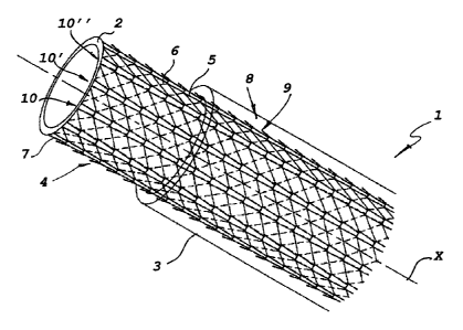
FIGS. 1 and 2 illustrate two preferred but non-exclusive embodiments
of the hose according to the invention, generically indicated with 1, which
can
comprise an inner tubular layer 2, an external tubular layer 3 and a
reinforcement
layer 4 interposed between the two inner 2 and outer 3 tubular layers.
The inner layer 2 and the outer layer 3 can be made of polymer
material, of plastic or rubber type, e.g. PVC. In a known manner, further
layers can
also be provided (not illustrated), placed inside the inner layer 2 and/or
outside the
outer layer 3.
CA 2803143 2017-12-21
The reinforcement layer 4 will be of knitted type with chain meshes of
tricot type, and can be made of textile fiber, e.g. polyamide or polyester.
Nevertheless, other synthetic or natural fiber types can also be used.
The inner 2 and outer 3 tubular layers will be substantially coaxial and
will extend along a longitudinal axis X.
The knitted reinforcement layer 4 will be wound in a spiral on the inner
layer 2 and will comprise a first and a second series of yarns, respectively 5
and 6,
wound in a spiral on the inner layer 2.
The two series of yarns 5, 6 have helical progression with substantially
identical pitch and will be knitted together to form a plurality of meshes 7,
7', 7", . . .
arranged on mesh courses, respectively 8, 8', 8", . . . and 9, 9', 9", . . .
inclined with
respect to the longitudinal axis X and mesh wales 10, 10', 10", . . .
substantially
parallel to the axis X. In particular, the meshes 7, 7', 7", . . . will also
be substantially
longitudinal.
According to one feature herein, each mesh 7, 7', 7", . . is formed by
a portion of a yarn 5 of the first series which defines a first chain eyelet
11, 11', 11", .
. . and by a portion of a yarn 6 of the second series which defines a second
chain
eyelet 12, 12', 12", . . .
In addition, each chain eyelet 11, 11', 11", . . ;
12, 12', 12", . . . is
substantially U-shaped, with an open end and a closed end and with a pair of
longitudinal sections, respectively 13, 14; 13', 14'; 13", 14", and 15, 16;
15', 16'; 15",
16", spaced from one another at the open end of the respective chain eyelet
and
CA 2803143 2017-12-21
9
joined to one another by substantially transverse section, respectively 17,
17', 17", . .
. and 18, 18', 18" at the closed end of the respective chain eyelet.
In particular, for each mesh wales 10, 10', 10", . . . meshes 7, 7', 7" will
be present, each formed by pairs of first chain eyelets 11, 11', 11", . . . ;
and second
chain eyelets 12, 12', 12", . . . substantially identical to each other and
having both
the respective substantially longitudinal sections 13, 14; 13', 14'; 13", 14",
and 15,
16; 15', 16'; 15", 16" and the respective substantially transverse sections
17, 17',
17", . . . and 18, 18', 18", . . . superimposed in a substantially complete
manner on
each other in a manner so as to define a reinforcement knitting 4 that is
generally
single-layer and locally double-yarn.
As is better visible in FIGS. 3 and 5, for each mesh 7, 7', 7", . . . the
respective first eyelet 11, 11', 11", . . . and second eyelet 12, 12', 12", .
. . can be
radially and/or frontally superimposed, and in any case will be mutually
knitted in
order to define a single chain mesh 7, 7', 7", . . . .
Naturally, each mesh 7 will be linked to a pair of adjacent meshes 7',
7", . . . of the same wales 10, 10', 10", . . . each of such meshes 7', 7"
being formed
by a first eyelet 11', 11", . . . and by a second eyelet 12', 12", . . .
substantially
identical with each other and superimposed in a substantially complete manner.
Preferably, the mesh courses 8, 8', 8", . . . of the first series of yarns 5
will be inclined with respect to the axis X with inclination opposite to that
of the mesh
courses 9, 9', 9", . . . of the second series of yarns 6 with respective
predetermined
inclination angles a, 6, which will preferably have equal but opposite value.
CA 2803143 2017-12-21
10
In a preferred but merely exemplifying manner, the inclination angles
can have values comprised between 200 and 80 and still more preferably
between
30 and 75 .
Advantageously, regardless of the respective inclination angles a, 13, in
a first configuration, illustrated in FIG. 1, the mesh courses 8, 8', 8", . .
. of the first
series of yarns 5 will be superimposed on the mesh courses 9, 9', 9", . . . of
the
second series of yarns 6 only at the respective eyelets 1 1, 1 1', 1 1", . . .
; 12, 12', 12",
. . ..
This particular configuration will allow preventing the reinforcement
layer 4 from having empty spaces between meshes 7, 7', 7", . . . of a same
courses
8, 8', 8", . . . ; 9, 9', 9", . . . having excessive extension, which would
lead to localized
reduction of the resistance to the bursting of the hose 1 at these zones.
In this manner, the reinforcement layer 4 will be double-yarn,
substantially only at the points of contact with the meshes 7, 7', 7", . . . .
The present invention will be even clearer by comparing FIG. 3 and
FIG. 4, in which two details are depicted of the same portion of a knitted
reinforcement layer 4 respectively of a hose 1 according to the invention and
of a
hose belonging to the state of the art, in which the meshes 7, 7', 7", . . .
are only
formed by yarn of one of the two series.
In a second configuration, illustrated in FIG. 2, the mesh courses 8, 8',
8", . . . of the first series of yarn 5 can be superimposed on the mesh wales
9, 9', 9",
CA 2803143 2017-12-21
11
. . . of the second series of yarn 6, also at a zone interposed between
contiguous
mesh wales 10, 10', 10".
In particular, the two hoses have mesh courses 8, 8', 8", . . . with the
same inclination. It is clear that the above-defined empty spaces, indicated
with
hatching in both the figures, have reduced extension for the hose 1 according
to the
invention with respect to the hose of the state of the art. In this manner,
excessive
localized swelling is prevented in the case of high internal pressures,
increasing both
the resistance to bursting and the kinking resistance properties.
The hose according to the invention can be obtained with a process
that provides for a step of manufacturing the inner layer 2 in polymer
material, e.g.
by means of extrusion, and a subsequent step of knitting of the first 5 and
second
series 6 of yarns, at the periphery of the inner layer 2 in order to form the
reinforcement layer 4 on the same.
In particular, the knitting step is executed with the two series of yarn 5, 6
placed in
rotation with predetermined directions around the inner layer 2 and by means
of a
plurality of needles 19 configured to be moved parallel to the axis X of the
inner layer
2 and to hook respective yarns 5, 6 and knit them together in order to define
the
mesh courses 8, 8', 8", . . . 9, 9', 9", . . . and the mesh wales 10, 10',
10", . . . of the
reinforcement layer 4.
Each needle 19 can hook a yarn of one of the two series 5, 6 in order
to make an eyelet 11, 12 designed to form a mesh 7.
CA 2803143 2017-12-21
12
For example, a needle 19 can hook a yarn of the first series 5 in order
to form a first eyelet 11, while a contiguous needle can hook, simultaneously
or
subsequently, a yarn of the second series 6 in order to form a second eyelet
12
superimposed on the first eyelet 11.
Advantageously, each needle 19 will be configured for simultaneously
hooking a yarn of the first series 5 and a yarn of the second series 6, as is
more
clearly visible in FIG. 9.
In this manner, each needle 19 will achieve, with every longitudinal
translation, a chain mesh 7, 7', 7", . . . comprising a first eyelet 11, 11',
11", . . .
formed by a yarn portion of the first series 5 and a second eyelet 12, 12',
12", . . .
formed by a yarn portion of the second series 6 identical to the first eyelet
11, 11',
11", . . and superimposed on the same in a substantially complete manner, to
form
a reinforcement knitting that is generally single-layer and locally of double-
yarn type.
In particular, the reinforcement layer 4 will have mesh wales 10, 10',
10", . . . substantially parallel to the axis X of the hose 1 and mesh courses
8, 8', 8",.
. . 9, 9', 9", . . inclined with respect to the same.
The two series of yarn 5, 6 will be mounted on substantially coaxial
rotating plates 20, 20', brought into rotation with substantially identical
speed in
opposite direction in order to obtain mesh courses having equivalent and
opposite
inclinations with respect to the longitudinal axis X of the hose 1.
CA 2803143 2017-12-21
13
The process can then comprise all the additional steps necessary for
completing the hose, such as the step of obtaining the outer layer 3, and such
steps
can vary as a function of the specific configuration of the hose 1.
The knitted reinforcement layer 4 can be obtained with the knitting
machine 21 illustrated in FIGS. 6, 8 and 10, having two spool-carrier plates
20, 20'
that are both motorized and possibly connected to one same motor 22.
The two plates 20, 20' will be coaxial and rotatable around the
longitudinal axis X defined by the hose 1. Each yarn of a series 5, 6 will
come from a
respective spool 23, 23', which can be present in the same number for each
plate
20,20'.
The latter will be associated with a device for distributing the yarns 24,
24', facing each other and mounted coaxial with the longitudinal axis X in
order to be
brought into rotation, preferably with the same speed and in opposite
direction, and
to wind the two series of yarn 5, 6 on the inner layer 2 with helical
progression and
inclination angles a, J3 that are equivalent and mutually opposite with
respect to the
axis X of the hose.
The machine 21 will also comprise a knitting head 25 having a sleeve
26, more clearly visible in FIG. 6, defining an axial passage 27 for the lower
layer 2
around which the needles 19 are circularly arranged.
The knitting head 25 will also comprise a cam 28 operatively
associated with the needles 19 in order to cause their alternating movement
along
respective longitudinal directions.
CA 2803143 2017-12-21
14
The cam 28 can have a number of crests 29 equal to the number of
yarn of each series 5, 6 i.e. equal to a multiple or a submultiple of the
number of
yarns of each series 5, 6.
Each needle 19 will be configured to simultaneously hook and work a
yarn of the first series 5 and a yarn of the second series 6 and obtain a
single-layer
knitted reinforcement 4 with each mesh wales 10, 10', 10", . . . defined both
by yarns
5 of the first series and by yarns 6 of the second series. In particular, the
single-layer
knitted reinforcement 4 will be of the double-yarn type at the meshes 7, 7',
7", . . . in
such a manner to have a resistance to the increased pressure associated with
high
malleability.
In addition, in a first configuration, illustrated in FIGS. 8 and 9, the
needles 19 will be configured to translate all in a synchronous manner and to
hook
respective pairs of first yarns 5 and second yarns 6, so as to achieve a
knitted layer
4 having a number of wales 10, 10', 10", . . equal to the number of yarns of
each
series 5, 6.
In an alternative configuration, shown in FIGS. 10 and 11, it will be
possible to identify two separate series of needles 19 operating in an
alternating
manner with respect to each other, for manufacturing a knitted layer 5 having
a
number of wales 10, 10', 10" equal to double to the number of yarns of each
series
5,6.
From that described above, it is clear that the invention attains the pre-
established objects, and in particular that of making a reinforcement mesh
with high
CA 2803143 2017-12-21
15
malleability and substantially unaffected by the expansion forces of the hose.
The
balanced structure of the knitting ensures that the twisting forces due to the
pressure
inside the hose are always compensated, even in the presence of variation of
the
inclination of the mesh courses, so that the hose is practically unaffected by
the
internal pressure variations of the transported fluid. The elementary meshes
formed
by means of knitting of both series of yarns confer malleability to the hose
and
reduce the possibility of its narrowing and obstruction.
The hose and the process according to the invention are susceptible to
numerous modifications and variants, all falling within the inventive concept
expressed in the enclosed claims.
CA 2803143 2017-12-21