Note: Descriptions are shown in the official language in which they were submitted.
1
CA 02803172 2013-01-16
- 1 -
IMPACT BAFFLE FOR CONTROLLING HIGH-PRESSURE FLUID JETS
AND METHODS OF CUTTING WITH FLUID JETS
The present invention refers to the field of machining of workpieces using
abrasive fluid jets. It specifically relates to an impact baffle for the high-
pressure fluid jets of a fluid jet cutting tool and methods of cutting through
a
workpiece.
Background
It has been known to use a fluid jet, typically a water jet, discharged at
high
pressure from a nozzle, for the machining, especially the cutting, of work
pieces. The jet diameter is typically in the order of around 1 mm. In the case
of so-called "abrasive water-jet cutting " (AWJ), water pressures of more than
300 MPa are used to generate a water jet with abrasive particles. Such a
water jet can be used as an omni-directional cutting tool for cutting wide
range
of metallic and non-metallic materials with thicknesses of up to 200 mm.
In large turbines, particularly steam turbines, blades can be for example
attached to the rotor by means of a pinned blade root where press-fitted or
interference-fitted pins are placed in boreholes extending through the blade
root and the rotor. Prior to their placement in the boreholes, the pins are
for
example cooled to low temperatures, e.g. by means of liquid nitrogen. Thus
slightly reduced in size, they are then pressed into the borehole with heavy-
duty tools, which results in a tight, high-tension fit between the pin and the
turbine rotor and blade root.
During turbine maintenance, the turbine blading must be removed and
replaced requiring the removal of the press-fit pins from their boreholes.
However, this is a difficult procedure as the space between the blade rows
can be confined, in some cases to dimensions as narrow as 15 mm (in case
of industrial steam turbines)
CA 02803172 2014-11-03
79291-145
- 2 -
The co-owned United States patent no. 7628678 describes the in-situ use of a
water jet tool having a nozzle that is arranged at an angle with respect to a
main body of the water jet tool. The water jet is directed over a portion of
the
surface of the pin and removes that portion thereby fragmenting the pin. In
order to minimise damage to the surrounding material, the portions removed
touches the interface between the pin and the surrounding solid material at a
minimal number of points and over a minimal extent of the interface.
Compact collecting devices for water jets have already been proposed, which
can be moved together with the water jet tool and can also be used in the
case of confined space conditions at the application site. Such devices are
described for example in the published European patent applications nos. EP
0244966 A2 and EP 0252657 A2 and the co-owned published United States
patent application no. US 2009/0178526 Al.
The '526
application shows a collecting device for detecting the first impact of the
high
pressure water jet upon the collecting device, and using a corresponding
signal for controlling the use of the water-jet tool, or detecting a
malfunction of
the collecting device and using a corresponding signal is used for terminating
the use of the water-jet tool.
In view of the known prior art, it is seen as an object of the invention to
improve the known collecting device, particularly for very confined spaces.
Summary
According to an aspect of the present invention, there is provided an impact
baffle to operate in conjunction with a jet cutting tool, the baffle including
an
impact layer and a laterally extended sensing layer to trigger a control
signal
for interrupting a cutting operation of the jet cutting tool after the impact
layer
is pierced by the jet cutting tool.
CA 02803172 2014-11-03
79291-145
- 3 -
In some embodiments of this aspect of the invention, the extended sensing
layer
triggers the signal when being at least partly penetrated. In a variant of
this
embodiment the extended sensing layer includes a fine mesh or grid of
conductive
layers.
In some embodiments, the impact baffle can further include a sensor
registering the
onset of an impact of the jet on the baffle, for example an accelerometer.
In some embodiments, the impact baffle can further include a sensor for a
detecting a
proper mounting and/or proximity sensor for registering whether the baffle is
in the
correct position facing the work piece.
In some embodiments, it is another preferred feature of impact baffle to have
a width
as measured in direction of the impacting jet of less than 20 mm or less than
15 mm,
preferably 5 mm to 15 mm, and even more preferably 5 mm to 10 mm, to enable
the
baffle to fit for example within very confined gaps to access work pieces to
be cut.
According to another aspect, there is provided a method of using thin impact
baffles
exposed to a fluid jet, the method including the steps of generating an
extended pre-
cut through the work piece to be cut while avoiding piercing followed by the
step of
piercing through the extended pre-cut to create the cut through the workpiece.
In a preferred embodiment of the method, the extended cut has two end zones at
which the cutting speed is reduced compared to the cutting speed when cutting
the
cut outside the end zones.
In a variant of this embodiment the cutting without piercing starts at a
central position
of the exposed face of the workpiece and is directed into a first direction
towards the
perimeter of the exposed face of the workpiece at a first cutting speed and
when
reaching a predetermined distance from the
CA 02803172 2014-11-03
79291-145
- 4 -
perimeter cutting without piercing is continued at a second reduced cutting
speed until the perimeter is reached, then the direction of cutting is
reverted
and cutting with piercing within the existing pre-cut is started until the
central
position is reached and cutting without piercing restarts at the central
position
and is directed into a second direction towards the perimeter of the exposed
face of the workpiece at the first cutting speed and when reaching the
predetermined distance from the perimeter cutting without piercing is
continued at the second reduced cutting speed until the perimeter is reached,
then the direction of cutting is reverted and cutting with piercing within the
existing pre-cut is started until the central position is reached again.
The first and second directions can be arbitrary chosen to split the workspace
but are probably best along the same diameter line. It is also possible to
alter
the sequence of the steps such that the end zones are cut after the zone
between the end zones is cut and pierced. The steps can be repeated to
generate more than one cut through the workpiece. In particular, it is
possible
to cut two cuts into bolts, screws, pins or other fastening devices in a cross
pattern to split them into four parts.
With this method the impact baffle is exposed to the high pressure fluid jet
for
a time period which is more than ten times shorter compared to known
methods. The exposure time of the impact baffle to the fluid jet of the jet
cutting tool can be reduced to 1 minute or less during the cutting of a
standard
turbine pin.
These and further embodiments of the invention will be apparent from the
following detailed description and drawings as listed below.
Brief Description of the Drawings
Exemplary embodiments of the invention will now be described, with
reference to the accompanying drawings, in which:
CA 02803172 2014-11-03
79291-145
- 5 -
FIG. 1 shows a jet cutting tool with an impact baffle applied to the cutting
of
pins in turbine rotor;
FIG. 2A is a schematic exploded view of a impact baffle in accordance with
an example of an embodiment of the present invention;
FIG. 2B shows the impact baffle of FIG. 2B in an assembled state; and
FIGs. 3A-3C illustrate variants of a cutting process to avoid long exposure
times of the impact baffle to the cutting jet.
Detailed Description
Aspects and details of examples of embodiments of the present invention are
described in further details in the following description using the example of
the
removal of pins holding blades in a steam turbine rotor.
Referring to FIG. 1 a turbine rotor 10 is shown having several turbine wheels
11 along its length. The turbine wheels 11 carry a circumferential row of
blades. In a typical refitting operation it is the task to separate the
blades,
which are detachably fastened on the turbine wheels 11 of the rotor 10, from
the rotor 10 by cutting the bolts or pins which are interference-fitted in
corresponding holes in the rotor structure. The pins fix the blade roots
within
annular grooves of the turbine wheel 11. A water-jet tool 18 cuts the pins in
the longitudinal direction. The pins are then removed from their holes using
for
example threads cut into their remaining parts. The turbine rotor of FIG. 1 is
shown mounted onto columns of a workshop floor. However, the same
operation can be performed in-situ with the cutting tool placed onto the
platform of a power station.
The water-jet tool 18 has two parallel oriented arms 181, 182. The arms can
be moved using hydraulics or electromagnetic motors. One arm carries the
CA 02803172 2014-11-03
=
79291-145
- 6 -
jet cutting tool and the other arm the impact baffle such that cutter and
baffle
are aligned across a gap when mounted in the correct position. To cut a pin,
the tool 18 is moved to position the rotor wheel inside the gap. Then water
loaded with abrasive material is supplied to an angled nozzle head via a high-
pressure water feed line. Once a pin in the rotor wheel is cut through, the
high-pressure water jet discharges on the other side of the turbine wheel 11
into the space between rotor wheels and can cause damage, if it is not
blocked and rendered harmless after the break-through by a jet catching
device such as the impact baffle of an embodiment of the present invention.
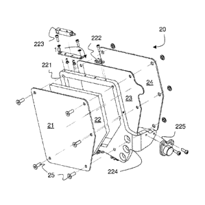
In FIG. 2A, an impact baffle 20 for a high-pressure water jet according to an
exemplary embodiment of the invention is reproduced as an exploded view.
This impact baffle 20 is particularly suitable for applications involving in-
situ
machining turbine rotors 10 as described above and components of power
plants, in which the space for collecting the water from the jet tool 18 is
limited. The external dimensions of the exemplary impact baffle 20 are
approximately 50 mm to 100 mm in lateral direction and 5 mm to 15 mm,
preferably 5 mm to 10 mm, in depth so that it can be introduced into the
narrow gap between adjacent turbine wheels. The width of the gap can be as
small as 15 mm in some types of turbines, for example the distance between
the first and second wheel in a industrial steam turbine.
The impact baffle 20 of FIG. 2A includes a sandwiched structure with several
layers 21, 22, 23,24 held together by several screws 25. Following the
direction of the jet there is a first protective layer 21 made of a thin layer
of a
soft material such as structural foam, which provides a cover and a fastening
for the impact plate 22. The impact plate 22 is surrounded by a steel frame
structure 221 which allows for an easy replacement of the impact plate 22.
The impact plate 22 is made of a very hard material such as tungsten carbide,
as it is used to stop the water jet during normal operation. Both the first
protective layer 21 and the impact plate 22 can be considered sacrificial
layers
CA 02803172 2014-11-03
=
79291-145
- 7 -
as damage and degradation of these layers are envisaged during the normal
operation of the impact baffle 20.
The thickness of the impact plate 22 contributes significantly to the overall
depth of the impact baffle and should be made as thin as possible while at the
same time preventing a piercing. In the current example the thickness of the
impact plate 22 is chosen to be around 5mm. Depending on the application,
the thickness of the impact plate 22 can be chosen to be between 1 mm and
mm or even between 1 mm and 5mm.
As is known from the co-owned published United States patent application
Publication no. US 2009/0178526 Al, an acceleration sensor 222 can be used to
register the impact of the water jet on the impact plate 22 indicating a
piercing or
breakthrough of the jet through the workpiece. Based on a signal from the
acceleration sensor 222, the cutting tool can then be moved to the next step
of the cutting operation.
The frame structure provides further support for a proximity switch 223 based
on induction which is used to monitor the proximity to the workpiece. The
frame includes an extension 224 for mounting the impact baffle onto the arm
182 of the cutting tool 18 as shown in FIG. 1. A contact switch 225 is used to
ensure that the baffle is safely mounted.
Also fixed to the frame is an extended sensing layer 23, which is used to
monitor the break-through of the jet through the impact plate 22. In the
present example the sensing layer 23 is essentially a printed circuit board
with
a pattern of conductive paths. If a path is interrupted, an emergency stop of
the water jet is triggered. This emergency stop is designed to secure the
fastest possible stop of the jet, bypassing or overriding all other pre-
programmed operations of the tool.
1
CA 02803172 2013-01-16
- 8 -
It is worth noting that this stop is an emergency operation normally reserved
only for the specific event of a piercing of the impact plate 22. As already
mentioned above, it is the impact plate 22 which acts as the stop for the
water
jet during normal operations and the signals from the acceleration sensor 222
are used to control normal cutting operations.
The back of the impact baffle 20 is a security plate 24, which is again made
of
very hard material to stop the water jet after it pierced through both, impact
plate 22 and sensing layer 23.
For the purpose of sending signals triggered or generated by impact baffle 20,
all sensors mounted on the impact baffle 20 are connected to a signal
processing device delivers corresponding control signals to the control unit
(not shown in the figures) of the jet cutting tool 18 . The impact baffle 20
thus
becomes part of the control system of the water-jet tool.
The impact baffle 20 and its parts are simply and inexpensively constructed
and represent easily exchangeable wear-resistant components. At least part
of its components including the first protective layer 21 and the impact plate
22, itself,are designed to be degraded and damaged already during normal
operations.
Impact baffles of the type described above with very thin jet impact or jet
absorption layers are best used with an altered cutting method, which takes
into consideration their limitations. A method of cutting a workpiece while
avoiding early degradation of a thin impact baffle, for example the impact
baffle above, is described schematically in the following making reference
particularly to FIG. 3.
In FIG. 3A there is shown a pin 30 fixing a turbine blade to the turbine rotor
as
the workpiece to be cut. The planned cut 31 is a horizontal cut across the
full
diameter of the bolt marked by dashed lines. It includes two end zones 311,
CA 02803172 2014-11-03
=
79291-145
-9-
312 located between the central zone of the cut and the circumference of the
bolt 30. Arrows in the drawing indicate the cutting scheme or operation. An
arrow denoted with v1 indicates a cutting path with a first cutting speed or
feed rate v1. An arrow denoted with v2 indicates a cutting path with a first
cutting speed or feed rate v2. The cutting speed v1 applied during the
cutting of the central zone is faster than the cutting speed v2 applied during
the cutting of the two end zones 311, 312.
The cutting operation seeks to control the cutting such that the workpiece
there is first a pre-cut cut into the workpiece avoiding piercing through
completely. And the workpiece is only pierced on a return path across a
previously cut zone or pre-cut. The return path within the existing pre-cut is
indicated by the dashed arrows in FIG. 3A. The required control parameters
can be gained from knowledge about the material to be cut, the rate of
penetration through such a material and the jet parameters or by conducting
preliminary experiments using the same material and jet parameters. Even
though the high-pressure fluid is blocked from exiting the cut through an
opening on the opposite side for much longer than in known methods, the
accuracy of the cut is sufficiently precise for the purpose of cutting bolts
and
similar cutting operations.
The FIGs. 3B and 3C illustrate how the above steps can be applied to
generate cuts across the workpiece in arbitrary directions and how the can be
applied twice or multiple times to generate several cuts through a common
point or central position 33 to split the workpiece into a corresponding
number
of parts, for example to facilitate the removal of interference-fitted pins.
Embodiments of the present invention have been described above purely by way
of example, and modifications can be made within the scope of the invention,
such
as specific dimensions or selections of materials. In particular the sensors
described can alternatively be based on different principles. For example the
i
CA 02803172 2013-01-16
- 10 -
integrity of the sensing layer can be monitored using the reflection or
refraction pattern of optical and acoustic waves guided through it.
Each feature disclosed in the specification, including the drawings, may be
replaced by alternative features serving the same, equivalent or similar
purposes, unless expressly stated otherwise.
Unless explicitly stated herein, any discussion of the prior art throughout
the
specification is not an admission that such prior art is widely known or forms
part of the common general knowledge in the field.
CA 02803172 2013-01-16
- 11 -
LIST OF REFERENCE SIGNS AND NUMERALS
turbine rotor 10
turbine wheel 11, 11'
water-jet tool 18
arms 181, 182
impact baffle 20
first protective layer 21
impact plate 22
frame structure 221
acceleration sensor 222
proximity switch 223
extension 224
contact switch 225
extended sensing layer 23
security plate 24
bolt 30
cut 31
end zones 311, 312
common point or central position 33
cutting speeds v1, v2