Note: Descriptions are shown in the official language in which they were submitted.
CA 02803363 2012-12-19
WO 2012/012182 PCT/US2011/042393
PRESSURE RESISTANT VACUUM/LABEL PANEL
CROSS-REFERENCE TO RELATED APPLICATIONS
[0001] This application claims priority to U.S. Utility Application No.
13/171,826, filed June 29, 2011, and the benefit of U.S. Provisional
Application
No. 61/360,084, filed on June 30, 2010. The entire disclosures of the above
applications are incorporated herein by reference.
FIELD
[0002] This disclosure generally relates to containers for retaining a
commodity, such as a solid or liquid commodity. More specifically, this
disclosure relates to a container having optimized horizontal ribs at an
optimum
perimeter length to act as a belt/strap to maintain container shape.
BACKGROUND AND SUMMARY
[0003] This section provides background information related to the
present disclosure which is not necessarily prior art. This section also
provides a
general summary of the disclosure, and is not a comprehensive disclosure of
its
full scope or all of its features.
[0004] As a result of environmental and other concerns, plastic
containers, more specifically polyester and even more specifically
polyethylene
terephthalate (PET) containers are now being used more than ever to package
numerous commodities previously supplied in glass containers. Manufacturers
and fillers, as well as consumers, have recognized that PET containers are
lightweight, inexpensive, recyclable and manufacturable in large quantities.
[0005] Blow-molded plastic containers have become commonplace in
packaging numerous commodities. PET is a crystallizable polymer, meaning
that it is available in an amorphous form or a semi-crystalline form. The
ability of
a PET container to maintain its material integrity relates to the percentage
of the
PET container in crystalline form, also known as the "crystallinity" of the
PET
container. The following equation defines the percentage of crystallinity as a
volume fraction:
1
CA 02803363 2012-12-19
WO 2012/012182 PCT/US2011/042393
% Crystallinity = ( P - Pa )x100
Pc -Pa
where p is the density of the PET material; pa is the density of pure
amorphous
PET material (1.333 g/cc); and pc is the density of pure crystalline material
(1.455 g/cc).
[0006] Container manufacturers use mechanical processing and
thermal processing to increase the PET polymer crystallinity of a container.
Mechanical processing involves orienting the amorphous material to achieve
strain hardening. This processing commonly involves stretching an injection
molded PET preform along a longitudinal axis and expanding the PET preform
along a transverse or radial axis to form a PET container. The combination
promotes what manufacturers define as biaxial orientation of the molecular
structure in the container. Manufacturers of PET containers currently use
mechanical processing to produce PET containers having approximately 20%
crystallinity in the container's sidewall.
[0007] Thermal processing involves heating the material (either
amorphous or semi-crystalline) to promote crystal growth. On amorphous
material, thermal processing of PET material results in a spherulitic
morphology
that interferes with the transmission of light. In other words, the resulting
crystalline material is opaque, and thus, generally undesirable. Used after
mechanical processing, however, thermal processing results in higher
crystallinity and excellent clarity for those portions of the container having
biaxial
molecular orientation. The thermal processing of an oriented PET container,
which is known as heat setting, typically includes blow molding a PET preform
against a mold heated to a temperature of approximately 250 F - 350 F
(approximately 121 C - 177 C), and holding the blown container against the
heated mold for approximately two (2) to five (5) seconds. Manufacturers of
PET
juice bottles, which must be hot-filled at approximately 185 F (85 C),
currently
use heat setting to produce PET bottles having an overall crystallinity in the
range of approximately 25% -35%.
[0008] Unfortunately, with some applications, as PET containers for
hot fill applications become lighter in material weight, it becomes
increasingly
2
CA 02803363 2012-12-19
WO 2012/012182 PCT/US2011/042393
difficult to create functional designs that can simultaneously resist fill
pressures,
absorb vacuum pressures, and withstand top loading forces. According to the
principles of the present teachings, the problem of expansion under the
pressure
caused by the hot fill process is improved by creating unique vacuum/label
panel
geometry that resists expansion, maintains shape, and shrinks back to
approximately the original starting volume due to vacuum generated during the
product cooling phase. The present teachings further improve top loading
functionality through the use of arches and column corners in some
embodiments.
[0009] Further areas of applicability will become apparent from the
description provided herein. The description and specific examples in this
summary are intended for purposes of illustration only and are not intended to
limit the scope of the present disclosure.
DRAWINGS
[0010] The drawings described herein are for illustrative purposes only
of selected embodiments and not all possible implementations, and are not
intended to limit the scope of the present disclosure.
[0011] FIG. 1 is a front view of an exemplary container incorporating
the features of the present teachings;
[0012] FIG. 2 is a side view of an exemplary container incorporating
the features of the present teachings;
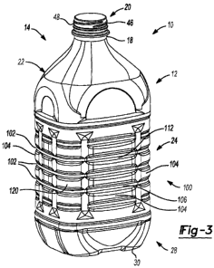
[0013] FIG. 3 is a plan view of an exemplary container incorporating
the features of the present teachings;
[0014] FIG. 4 is a bottom view of an exemplary container incorporating
the features of the present teachings;
[0015] FIG. 5 is a cross-sectional view of an exemplary container
incorporating the features of the present teachings taken along line 5-5 of
FIG. 1;
[0016] FIG. 6 is a cross-section view of an exemplary container
incorporating the features of the present teachings;
[0017] FIG. 7 is a cross-sectional view of the finish of an exemplary
container incorporating the features of the present teachings; and
3
CA 02803363 2012-12-19
WO 2012/012182 PCT/US2011/042393
[0018] FIG. 8 is a schematic view illustrating the first perimeter length
and the second perimeter length.
[0019] Corresponding reference numerals indicate corresponding parts
throughout the several views of the drawings.
DETAILED DESCRIPTION
[0020] Example embodiments will now be described more fully with
reference to the accompanying drawings. Example embodiments are provided
so that this disclosure will be thorough, and will fully convey the scope to
those
who are skilled in the art. Numerous specific details are set forth such as
examples of specific components, devices, and methods, to provide a thorough
understanding of embodiments of the present disclosure. It will be apparent to
those skilled in the art that specific details need not be employed, that
example
embodiments may be embodied in many different forms and that neither should
be construed to limit the scope of the disclosure.
[0021] The terminology used herein is for the purpose of describing
particular example embodiments only and is not intended to be limiting. As
used
herein, the singular forms "a", "an" and "the" may be intended to include the
plural forms as well, unless the context clearly indicates otherwise. The
terms
"comprises," "comprising," "including," and "having," are inclusive and
therefore
specify the presence of stated features, integers, steps, operations,
elements,
and/or components, but do not preclude the presence or addition of one or more
other features, integers, steps, operations, elements, components, and/or
groups
thereof. The method steps, processes, and operations described herein are not
to be construed as necessarily requiring their performance in the particular
order
discussed or illustrated, unless specifically identified as an order of
performance.
It is also to be understood that additional or alternative steps may be
employed.
[0022] When an element or layer is referred to as being "on", "engaged
to", "connected to" or "coupled to" another element or layer, it may be
directly on,
engaged, connected or coupled to the other element or layer, or intervening
elements or layers may be present. In contrast, when an element is referred to
as being "directly on," "directly engaged to", "directly connected to" or
"directly
4
CA 02803363 2012-12-19
WO 2012/012182 PCT/US2011/042393
coupled to" another element or layer, there may be no intervening elements or
layers present. Other words used to describe the relationship between elements
should be interpreted in a like fashion (e.g., "between" versus "directly
between,"
"adjacent" versus "directly adjacent," etc.). As used herein, the term
"and/or"
includes any and all combinations of one or more of the associated listed
items.
[0023] Although the terms first, second, third, etc. may be used herein
to describe various elements, components, regions, layers and/or sections,
these elements, components, regions, layers and/or sections should not be
limited by these terms. These terms may be only used to distinguish one
element, component, region, layer or section from another region, layer or
section. Terms such as "first," "second," and other numerical terms when used
herein do not imply a sequence or order unless clearly indicated by the
context.
Thus, a first element, component, region, layer or section discussed below
could
be termed a second element, component, region, layer or section without
departing from the teachings of the example embodiments.
[0024] Spatially relative terms, such as "inner," "outer," "beneath",
"below", "lower", "above", "upper" and the like, may be used herein for ease
of
description to describe one element or feature's relationship to another
element(s) or feature(s) as illustrated in the figures. Spatially relative
terms may
be intended to encompass different orientations of the device in use or
operation
in addition to the orientation depicted in the figures. For example, if the
device in
the figures is turned over, elements described as "below" or "beneath" other
elements or features would then be oriented "above" the other elements or
features. Thus, the example term "below" can encompass both an orientation of
above and below. The device may be otherwise oriented (rotated 90 degrees or
at other orientations) and the spatially relative descriptors used herein
interpreted accordingly.
[0025] This disclosure provides for a container being made of PET and
incorporating a series of horizontal rib features having an optimized size and
shape that resists container expansion caused by hot fill pressure and acts as
a
belt/strap to help maintain container shape.
5
CA 02803363 2012-12-19
WO 2012/012182 PCT/US2011/042393
[0026] It should be appreciated that the size and specific configuration
of the container may not be particularly limiting and, thus, the principles of
the
present teachings can be applicable to a wide variety of PET container shapes.
Therefore, it should be recognized that variations can exist in the present
embodiments. That is, it should be appreciated that the teachings of the
present
disclosure can be used in a wide variety of containers, including
reusable/disposable packages including resealable plastic bags (e.g., ZipLock
bags), resealable containers (e.g., TupperWare containers), dried food
containers (e.g., dried milk), drug containers, chemical packaging, squeezable
containers, recyclable containers, and the like.
[0027] Accordingly, the present teachings provide a plastic, e.g.
polyethylene terephthalate (PET), container generally indicated at 10. The
exemplary container 10 can be substantially elongated when viewed from a side
and rectangular when viewed from above. Those of ordinary skill in the art
would appreciate that the following teachings of the present disclosure are
applicable to other containers, such as rectangular, triangular, pentagonal,
hexagonal, octagonal, polygonal, or square shaped containers, which may have
different dimensions and volume capacities. It is also contemplated that other
modifications can be made depending on the specific application and
environmental requirements.
[0028] In some embodiments, container 10 has been designed to
retain a commodity. The commodity may be in any form such as a solid or semi-
solid product. In one example, a commodity may be introduced into the
container during a thermal process, typically a hot-fill process. For hot-fill
bottling applications, bottlers generally fill the container 10 with a product
at an
elevated temperature between approximately 155 F to 205 F (approximately
68 C to 96 C) and seal the container 10 with a closure before cooling. In
addition, the plastic container 10 may be suitable for other high-temperature
pasteurization or retort filling processes or other thermal processes as well.
In
another example, the commodity may be introduced into the container under
ambient temperatures.
6
CA 02803363 2012-12-19
WO 2012/012182 PCT/US2011/042393
[0029] As shown in FIG. 1, the exemplary plastic container 10
according to the present teachings defines a body 12, and includes an upper
portion 14 having a cylindrical sidewall 18 forming a finish 20. Integrally
formed
with the finish 20 and extending downward therefrom is a shoulder portion 22.
The shoulder portion 22 merges into and provides a transition between the
finish
20 and a sidewall portion 24. The sidewall portion 24 extends downward from
the shoulder portion 22 to a base portion 28 having a base 30. In some
embodiments, sidewall portion 24 can extend down and nearly abut base 30,
thereby minimizing the overall area of base portion 28 such that there is not
a
discernable base portion 28 when exemplary container 10 is uprightly-placed on
a surface.
[0030] The exemplary container 10 may also have a neck 23. The
neck 23 may have an extremely short height, that is, becoming a short
extension
from the finish 20, or an elongated height, extending between the finish 20
and
the shoulder portion 22. The upper portion 14 can define an opening for
filling
and dispensing of a commodity stored therein. Although the container is shown
as a beverage container, it should be appreciated that containers having
different shapes, such as sidewalls and openings, can be made according to the
principles of the present teachings.
[0031] The finish 20 of the exemplary plastic container 10 may include
a threaded region 46 having threads 48, a lower sealing ridge 50, and a
support
ring 51. The threaded region provides a means for attachment of a similarly
threaded closure or cap (not shown). Alternatives may include other suitable
devices that engage the finish 20 of the exemplary plastic container 10, such
as
a press-fit or snap-fit cap for example. Accordingly, the closure or cap
engages
the finish 20 to preferably provide a hermetical seal of the exemplary plastic
container 10. The closure or cap is preferably of a plastic or metal material
conventional to the closure industry and suitable for subsequent thermal
processing.
[0032] In some embodiments, the container 10 can comprise a
label/vacuum panel area 100 generally disposed along sidewall portion 24. In
some embodiments, panel 100 can be disposed in other areas of the container
7
CA 02803363 2012-12-19
WO 2012/012182 PCT/US2011/042393
10, including the base portion 28 and/or shoulder portion 22. Panel area 100
can comprise a series or plurality of rib members 102 generally disposed
horizontally about container 10. Rib members 102 can be formed to have
minimum curves and radii for improved structural integrity, and less perimeter
length compared to the perimeter of adjacent surfaces, such as lands 104.
Through their structure, rib members 102 are capable of resisting the force of
internal pressure by acting as a "belt" that limits the "unfolding" of the
cosmetic
geometry of the container that makes up the exterior design.
[0033] By way of non-limiting example and with particular reference to
FIGS. 1 and 8, the rib members 102 can be formed to have a generally
consistent and uniform shape throughout its circumferential track about
container
10. Moreover, rib members 102 can specifically comprise a generally narrow
central portion 106 extending horizontally about container 10 defining a first
perimeter length 110a (see FIG. 8). Central portion 106 can transition to
adjacent lands 104 via a continuous, inclined portion or surface 112 (see
FIGS.
1-3). Surface 112 can provide a transition surface between central portion 106
and the varying shape of lands 104, which can itself include various features
and
contours. Adjacent lands 104 can similarly define a second perimeter length
110b (see FIG. 8). Second perimeter length 110b of adjacent lands 104 is
greater than first perimeter length 110a of central portion 106. In some
embodiments, rib members 102 can define a groove or other inwardly-directed
rib feature. Rib members 102 can further extend around corners formed in the
container to thereby strengthen the container.
[0034] In some embodiments, by way of non-limiting example, it has
been found that the optimum perimeter length of rib members 102, specifically
first perimeter length 110a, should be approximately 3-5% less than the
adjacent
perimeter geometry, specifically second perimeter length 110b. That is, in
some
embodiments, the first perimeter length 110a can be 348.84mm and the second
perimeter length 110b can be 360.96mm. Moreover, in some embodiments, that
depth of rib member 102 compared to adjacent lands 104 can be approximately
equal to about one half of the on-center distance between adjacent rib members
102. Still further, in some embodiments, the overall height of rib members 102
8
CA 02803363 2012-12-19
WO 2012/012182 PCT/US2011/042393
(when viewed from the front) can be approximately equal to the on-center
distance between adjacent rib members 102. Still further, in some
embodiments, the overall height of panel area 100 can generally equal about
50% (e.g. 40-60%) of the overall height of the container 10 (when viewed from
the front).
[0035] Distribution of rib members 102 has further been found to
improve the structural integrity of container 10. Specifically, in some
embodiments, it has been found that rib members 102 can be disposed parallel
and equally spaced along sidewall portion 24 and/or panel area 100. That is,
in
some embodiments, performance was optimized by using five (5) rib members
102 equally spaced within a 4.2" high label panel (i.e. panel area 100), or
about
one rib every 0.7" vertically. Rib members 102 can be generally located at a
central portion of sidewall portion 24, where expansion and contraction forces
are most extreme.
[0036] In some embodiments, it has also been found that improved
performance is realized by continuing rib member 102 within and through any
corner features 120 formed in container 10. In this way, the belt function of
rib
member 102 is improved and maximized, thereby adding stiffness and resisting
roll out under pressure.
[0037] By using the principles of the present teachings, the expansion
under fill pressure of 2.3psi was reduced from 111 cc to 83cc compared to
current panel design. This is an improvement of about 25% over typical or
conventional panel design.
[0038] It should be appreciated that the principles of the present
teachings further provide a container that is particularly well-suited to
resist
ovalization and thus maintain a rectangular shape (or other desired shape)
during filling compared to similar designs not using the rib members of the
present teachings. During filling, the container of the present teachings is
often
under a vacuum due to cooling and thus exhibits a shrinking response. The
present container, however, is unique in that is expands during initial
filling an
amount that is generally equal to the amount of shrinkage that occurs during
cooling, thereby resulting in a final, post-filled and cooled shape that
closely
9
CA 02803363 2012-12-19
WO 2012/012182 PCT/US2011/042393
conforms to an initial, pre-filled shape. It should thus be understood that
the
container of the present teachings is capable of maintaining an intended shape
pre- versus post-filling.
[0039] One skilled in the art will recognize that containers such as that
in the present application can often be exposed to vacuum forces created
during
cooling of the commodity. It is thus important for the container to adequately
manage such forces. In the case of the container of the present teachings, it
has
been found that the residual vacuum within the container following cooling is
generally less than about 15mm Hg.
[0040] The foregoing description of the embodiments has been
provided for purposes of illustration and description. It is not intended to
be
exhaustive or to limit the invention. Individual elements or features of a
particular embodiment are generally not limited to that particular embodiment,
but, where applicable, are interchangeable and can be used in a selected
embodiment, even if not specifically shown or described. The same may also be
varied in many ways. Such variations are not to be regarded as a departure
from
the invention, and all such modifications are intended to be included within
the
scope of the invention.